Table of Contents
Advertisement
Quick Links
Advertisement
Chapters
Table of Contents

Related Manuals for Microscan Quadrus EZ Reader


Summary of Contents for Microscan Quadrus EZ Reader
- Page 1 Quadrus EZ Reader User's Manual P/N 83-006700 Rev T...
- Page 2 The information and specifications described in this manual are subject to change without notice. Latest Manual Version For the latest version of this manual, see the Download page on our web site at www.microscan.com. For technical support email helpdesk@microscan.com. Microscan Systems, Inc.
-
Page 3: Limitation Of Liability
Limitation of Liability In no event shall Microscan Systems Inc. be liable to you or any third party for any special, incidental, or consequential damages (including, without limitation, indirect, special, punitive, or exemplary damages for loss of business, loss of profits, business interruption, or loss of business information), whether in contract, tort, or otherwise, even if Microscan Systems Inc. -
Page 4: Table Of Contents
Read Cycle by ESP................. 3-2 Read Cycle Serial Commands ..............3-3 Read Cycle Setup ................... 3-4 Multisymbol ..................... 3-5 Trigger ..................... 3-7 Serial Trigger..................3-13 End of Read Cycle ................3-15 Active Camera ..................3-17 Capture Mode..................3-18 Quadrus EZ Reader User’s Manual... - Page 5 Synchronous Trigger ................5-32 EZ Button....................5-34 Input 1....................5-38 Output 1 Parameters ................5-39 Output 2 Parameters ................5-52 Output 3 Parameters ................5-54 Chapter 7 Symbol Quality Symbol Quality by ESP ................6-2 Quadrus EZ Reader User’s Manual...
- Page 6 CMOS Image Sensor ................9-15 Illumination Source ................9-17 Thresholding..................9-18 Image Processing Settings..............9-19 Hollow Mode..................9-21 Mirrored Image ..................9-22 Other Camera Parameters ..............9-23 Chapter 11 IP Database IP Database by ESP................10-2 Quadrus EZ Reader User’s Manual...
- Page 7 Output Format Serial Commands ............14-2 Output Format Status ................14-3 Format Assign ..................14-4 Format Extract ..................14-5 Format Insert ..................14-7 Output Filter Configuration ..............14-9 Ordered Output Filter................14-13 Chapter 16 Ethernet Step 1 Setup..................15-2 Quadrus EZ Reader User’s Manual...
- Page 8 Appendix K Rapid Capture Mode ............A-28 Appendix L Object Detector ..............A-30 Appendix M Operational Tips ..............A-31 Appendix N Embedded Menus..............A-32 Appendix O Interface Standards ............A-33 Appendix P Multidrop Communications ..........A-34 Appendix Q Glossary of Terms .............A-37 viii Quadrus EZ Reader User’s Manual...
-
Page 9: Host Communications
There are four ways to configure and test the Quadrus EZ: 1. EZ button. 2. Microscan’s Windows-based ESP (Easy Setup Program), which offers point-and-click ease of use and visual responses to user adjustments. 3. Serial commands, such as <K100,1>, that can be sent from ESP’s Terminal window or another terminal program. - Page 10 About the Quadrus EZ Reader User’s Manual About the Quadrus EZ Reader User’s Manual This manual provides complete information on setting up, installing, and configuring the reader. The chapters are presented in the order in which a reader might be set up and made ready for operation.
- Page 11 • Wavelength: 464 nm; 518 nm; 635 nm. • Location of the Quadrus EZ’s LED aperture window: LED Aperture Window • CAUTION: Use of controls or adjustments or performance of procedures other than those specified herein may result in hazardous radiation exposure. Quadrus EZ Reader User’s Manual...
-
Page 12: Statement Of Agency Compliance
This equipment is in compliance or approved by the following organizations: • CDRH (Center for Devices & Radiological Health) • FCC (Federal Communications Commission) • CE (Conformité Européenne) • BSMI (Bureau of Standards, Metrology and Inspection) Quadrus EZ Reader User’s Manual... -
Page 13: Quick Start
Detailed setup information for installing the reader into the actual application can be obtained in the subsequent chapters. In addition to ESP, you can send commands to your reader by serial commands and through the reader’s embedded menus. Quadrus EZ Reader User’s Manual... -
Page 14: Step 1 Check Required Hardware
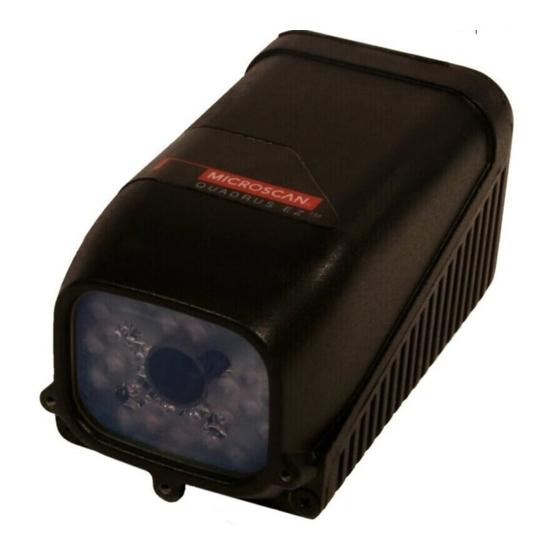
Step 1 — Check Required Hardware To get started with just the EZ Button You will need: • A Quadrus EZ Reader (1), FIS 6700-XXXX. • An IB-150 Kit, 98-000040-02, which includes a cable, 61-000034-02, and the IB-150 Interface Box (2), 99-000008-02. -
Page 15: Step 2 Connect The System
You can connect the Quadrus EZ by EZ button, RS-232, or TCP-IP (Ethernet). Connecting for EZ Button Setup without a Host • Connect the Quadrus EZ Reader to the IB-150 Kit, 98-000040-02. • Connect Power Supply. • Apply power to the reader. -
Page 16: Step 3 Position Reader And Symbol
• Avoid excessive skew or pitch. Maximum skew is ±30°; maximum pitch is ±30°. Note: For instant setup and validation, the Quadrus EZ can be hand-held or laid on its side; but for accuracy a mounting stand such as the one shown above is recommended. Quadrus EZ Reader User’s Manual... -
Page 17: Step 4 Install Esp
ESP provides a quick and easy way to set up and configure your reader. If installing from a Microscan Installation and Support CD: 1. Insert your Microscan Installation and Support CD in your computer’s CD drive. 2. Choose ESP Software from the main menu. -
Page 18: Step 5 Select Model
ESP, uncheck “Show this window at Startup”. 2. Select the default reader name (Quadrus EZ-1), or type a name of your choice in the Description text field and click OK. 3. Click when this dialog appears: Quadrus EZ Reader User’s Manual... -
Page 19: Step 6 Select Communications Protocol
IP addresses, enter the IP address in the dialog box. 2. Click Connect. Tip: If you do not see either the CONNECTED DISCONNECTED messages at the bottom of your dialog, try expanding the ESP window horizontally. Quadrus EZ Reader User’s Manual... -
Page 20: Step 7 Locate The Symbol In The Fov
You will see the blue X-pattern. 2. Center the X-pattern on the symbol. Note: To end all EZ button functions, press the EZ button and quickly release. Quadrus EZ Reader User’s Manual... - Page 21 X-pattern. 2. You will see the X-pattern in front of the reader. 3. Center the X-pattern over the symbol you want to read. 4. Click the Stop button to end the locate mode. Quadrus EZ Reader User’s Manual...
-
Page 22: Step 8 Calibrate Settings
After a moment the symbol’s data and related features will be presented under the “Symbol Information” box below the image display window. Calibrate by Serial Command Send <op,6,1> to begin calibration. Send <op,6,0> to end calibration. 1-10 Quadrus EZ Reader User’s Manual... -
Page 23: Step 9 Perform Readability Test
2. To end the test, click the Stop button. Testing by Serial Command You can also start a test with the <C> <Cp> command and end it with the <J> command. 1-11 Quadrus EZ Reader User’s Manual... -
Page 24: Step 10 Applications
• Format data for output by clicking the Output Format button. For details, see ESP Help in the pulldown menu. The window on the left represents the tree control. The window on the right is where image captures are displayed. 1-12 Quadrus EZ Reader User’s Manual... -
Page 25: Step 11 Make Menu Changes And Save In Esp
Same as above, except that these settings are saved to a special section of NOVRAM. Note: This option must be enabled under the Options pull down menu before it will be available as a save option. 1-13 Quadrus EZ Reader User’s Manual... -
Page 26: Video Output Option
You can connect a remote video monitor (RS-170/monochrome, non-interlaced) via the video output port on the back of the Quadrus EZ Reader and view live video or triggered events such as a good read, no read, or slide show of on-going captures. -
Page 27: Communications
This section tells how to set up communications parameters with the host and an auxiliary terminal. With Microscan’s ESP (Easy Setup Program), configuration changes can be made in the ESP menus, then sent and saved to your reader. The user can also send serial commands to the reader via the ESP’s Terminal window. -
Page 28: Communications By Esp
Applications menu. Click this button to bring up the Communications parameters. To open nested options, single-click the +. To change a setting, double-click the setting and use your cursor to scroll through the options. Quadrus EZ Reader User’s Manual... -
Page 29: Communications Serial Commands
<K151,daisy chain reader #,daisy chain reader ID> <K125,IP address,subnet address,gatewayaddress,IP Ethernet Configuration address mode,primary TCP port,video TCP port> Preamble <K141,status,preamble characters> Postamble <K142,status,postamble characters> Response Timeout <K143,response timeout> <K145,status> Aux Port System Data Status <K146,aux port system data> Quadrus EZ Reader User’s Manual... -
Page 30: Rs-232/422 Host Port
Only changed if necessary to match host setting. One or two bits added to the end of each character to indicate the end of Definition: the character. Serial Cmd: <K100,baud rate,parity,stop bits,data bits> Default: Options: 0 = One 1 = Two Quadrus EZ Reader User’s Manual... -
Page 31: Data Bits, Host Port
Only changed if necessary to match host setting. One or two bits added to the end of each character to indicate the end of Definition: the character. Serial Cmd: <K100,baud rate,parity,stop bits,data bits> Default: Options: 0 = Seven 1 = Eight Quadrus EZ Reader User’s Manual... -
Page 32: Host Port Protocol
Used only with RS-232. This option enables the host to send the XON and XOFF command as a Definition: single byte transmission command of start (^Q) or stop (^S). Serial Cmd: <K140,1> Quadrus EZ Reader User’s Manual... -
Page 33: Polling Mode D
User Defined is considered to be in a polled mode only if an address has Definition: been assigned. Serial Cmd: <K140,6RES,address,REQ,EOT,STX,ETX,ACK,NAK,from host> Default: No address Options: Any ASCII character except a NULL < , or >. Quadrus EZ Reader User’s Manual... - Page 34 If From Host is disabled, the defined protocol is not included. If From Host is enabled, the defined protocol must be included. Serial Cmd: <K140,6,RES,address,REQ,EOT,STX,ETX,ACK,NAK,from host> Default: Disabled Options: 0 = Disabled 1 = Enabled Quadrus EZ Reader User’s Manual...
-
Page 35: User Defined Multidrop
Note: Typically, parameters in User Defined Multidrop are defined by first enabling Mul- tidrop, then enabling User Defined Multidrop. This pre-loads multidrop characters into the parameters. Then changes are made to individual characters to match the host or other requirements. Quadrus EZ Reader User’s Manual... -
Page 36: Host 422 Status
Host 422 if enabled allows communication through the 422 I/O lines. Definition: When Host 422 is enabled, RS-232 is disabled. When Host 422 is disabled, RS-232 is enabled. Serial Cmd: <K102,host 422> Default: Disabled Options: 0 = Disabled 1 = Enabled 2-10 Quadrus EZ Reader User’s Manual... -
Page 37: Rs-232 Auxiliary Port
1 or 0 so that the total number of 1 bits in the data field is even or odd. <K101,aux port mode,baud rate,parity,stop bits,data bits,daisy chain ID Serial Cmd: status,daisy chain ID> Default: None Options: 0 = None 1 = Even 2 = Odd 2-11 Quadrus EZ Reader User’s Manual... -
Page 38: Auxiliary Port Mode
0 = Disabled 1 = Transparent 2 = Half duplex Options: 3 = Full duplex 4 = Daisy chain 5 = Command Processing Note: RS-232 host and aux port are available with full functionality. 2-12 Quadrus EZ Reader User’s Manual... -
Page 39: Transparent Mode
Data initiated from the Host Host • All host data is echoed to the auxiliary port in Port unpolled mode. Reader <K101,aux port mode,baud rate,parity,stop bits,data bits,daisy chain ID status,daisy chain ID> Serial Cmd: 1 = Transparent 2-13 Quadrus EZ Reader User’s Manual... -
Page 40: Half Duplex Mode
Data is initiated from the Host • All host data is echoed to the auxiliary port in unpolled mode. Host Port Reader <K101,aux port mode,baud rate,parity,stop bits,data bits> Serial Cmd: 2 = Half Duplex 2-14 Quadrus EZ Reader User’s Manual... -
Page 41: Full Duplex Mode
Data initiated from the Host • All host data is echoed to the auxiliary port in Host Port unpolled mode. Reader <K101,aux port mode,baud rate,parity,stop bits,data bits,daisy chain ID status,daisy chain ID> Serial Cmd: 3 = Full duplex 2-15 Quadrus EZ Reader User’s Manual... -
Page 42: Daisy Chain Mode
The above example is based on the best case. Other factors such as baud rate, dynamic focus timing, number of characters in a given symbol, and the number of secondary readers in the daisy chain can affect timing and may need to be included in your calculations for complete accuracy. 2-16 Quadrus EZ Reader User’s Manual... -
Page 43: Command Processing Mode
2. If the last command came from the host port, then externally triggered read cycle data will only be output to the host port. <K101,aux port mode,baud rate,parity,stop bits,data bits,daisy chain ID Serial Cmd: status,daisy chain ID> Options: 5 = Command Processing 2-17 Quadrus EZ Reader User’s Manual... -
Page 44: Daisy Chain Id Status
A one or two character prefix which identifies the particular daisy chain Definition: reader from which the data is being sent. <K101,aux port mode,baud rate,parity,stop bits,data bits,daisy chain ID sta- Serial Cmd: tus,daisy chain ID> Default: Options: Any one or two ASCII characters. 2-18 Quadrus EZ Reader User’s Manual... -
Page 45: Daisy Chain Autoconfigure
3. If necessary, set the master reader to Edge. After Autoconfigure you may set the master reader to Edge (E) but the other readers must remain in Serial (S): Secondary Secondary Master Host Reader Reader Reader 2-19 Quadrus EZ Reader User’s Manual... -
Page 46: Daisy Chain Remote Secondary Reader Id
ID Reader 1 = 2/; ID Reader 2 = 3/; etc. Options: Any two characters except NULL < , or >. Note: After a secondary reader accepts a new ID, it automatically invokes a reset-with- save command. 2-20 Quadrus EZ Reader User’s Manual... -
Page 47: Network
Use this to configure a subnet mask that is compatible with the host network and the reader's IP address. Serial Cmd: <K125,IP address,subnet address,gatewayaddress,IP address mode,primary TCP port,video TCP port> Default: 255.255.255.0 Options: 0.0.0.0 to 255.255.255.255 2-21 Quadrus EZ Reader User’s Manual... -
Page 48: Gateway Address
The port number is configured for the convenience/preference of the host system. Note: The primary TCP port and the video TCP must be different. Serial Cmd: <K125,IP address,subnet address,gateway address,IP address mode,primary TCP port,video TCP port> Default: 2001 Options: 1024 to 65535 2-22 Quadrus EZ Reader User’s Manual... - Page 49 Note: The primary TCP port and the video TCP must be different. Usage: The port number is configured for the convenience/preference of the host system. Serial Cmd: <K125,IP address,subnet address,gateway address,IP address mode,pri- mary TCP port,video TCP port> Default: 2002 Options: 1024 to 65535 2-23 Quadrus EZ Reader User’s Manual...
-
Page 50: Preamble
(with the space key). This has the effect of allowing the control key to be recognized as a part of the control character. Next hold down the control key while typing the desired character. Example: Space CNTL-m to enter ^M. 2-24 Quadrus EZ Reader User’s Manual... -
Page 51: Postamble
(with the space key). This has the effect of allowing the control key to be recognized as a part of the control character. Next hold down the control key while typing the desired character. Example: Space CNTL-m Space CNTL-j to enter ^M^J. 2-25 Quadrus EZ Reader User’s Manual... -
Page 52: Response Timeout
Time the reader will wait before timing out if ACK, NAK, and ETX are Definition: enabled, and a host response is expected. Serial Cmd: <K143,response timeout> Default: (in 10mS increments = 20mS) Options: 0 to 255 (A zero (0) setting causes an indefinite wait.) 2-26 Quadrus EZ Reader User’s Manual... -
Page 53: Lrc Status
(two 1s = 0, two 0s = 0, a 1 and a 0 = 1). The extra LRC character is then appended to the transmission and the receiver (usually the host) performs the same addition and compares the results. Serial Cmd: <K145,status> Default: Disabled Options: 0 = Disabled 1 = Enabled 2-27 Quadrus EZ Reader User’s Manual... -
Page 54: Aux Port System Data Status
Aux Port System Data Status Aux Port System Data Status Definition: When enabled, directs data from the reader to the auxiliary port. Serial Cmd: <K146,aux port system data> Default: Disabled Options: 0 = Disabled 1 = Enabled 2-28 Quadrus EZ Reader User’s Manual... - Page 55 After you’ve established communications and completed basic read rate testing, you will need to address the spatial and timing parameters associated with your application. Note: The characters NULL <> can only be entered through embedded menus, not through ESP or serial commands. Quadrus EZ Reader User’s Manual...
-
Page 56: Read Cycle By Esp
Read Cycle by ESP Click this button to bring up the Read Cycle menu. To open nested options, sin- gle-click the +. To change a setting, double-click the setting and use your cursor to scroll through the options. Quadrus EZ Reader User’s Manual... -
Page 57: Read Cycle Serial Commands
Capture Timing ,,,,,,,,time between capture 7 and 8> <K243,switching mode,number of internal camera captures, Dual Camera Operations number of external camera captures,internal camera timeout, external camera timeout> Store Noread Image <K244,image storage type,image storage mode> Quadrus EZ Reader User’s Manual... -
Page 58: Read Cycle Setup
10. Decide if you need to alternate between cameras, with Switching Mode. 11. Save settings to the IP database. Note: With a CCD sensor, images can be captured at a rate of 60/second. In CMOS, capture rate is 30/second. Quadrus EZ Reader User’s Manual... -
Page 59: Multisymbol
1). Number of Symbols Number of Symbols is the number of different symbols that can be read in Definition: a single read cycle. Serial Cmd: <K222,number of symbols,multisymbol separator> Default: Options: 1 to 6 Quadrus EZ Reader User’s Manual... -
Page 60: Multisymbol Separator
Note: If a NULL is entered for the multisymbol separator, the multisymbol separator output will be disabled. Note: If noread messages are disabled and there are noreads occurring, separators will only be inserted between symbol data outputs. Quadrus EZ Reader User’s Manual... -
Page 61: Trigger
In Continuous Read, trigger input options are disabled, the reader is always in the read cycle, and it will attempt to decode and transmit every capture. Definition: When To Output and Noread options have no affect on Continuous Read. Serial Cmd: <K200,0> Quadrus EZ Reader User’s Manual... -
Page 62: Continuous Read 1 Output
Note: If Trigger Mode is set to Continuous Read 1 Output, Number of Symbols will default to 1 (if set to any number greater than 1). Quadrus EZ Reader User’s Manual... -
Page 63: External Trigger Level
Associated waveforms assume External Trigger State is set to Active On. End Read Cycle: The same object, moving out of the detector beam, causes another change in the trigger state, ending the read cycle. Trigger Level Quadrus EZ Reader User’s Manual... -
Page 64: External Trigger Edge
This signal initiates a new read cycle and ends the pre- vious read cycle unless Timeout is enabled and a good read or timeout has not occurred. Trigger Edge 3-10 Quadrus EZ Reader User’s Manual... -
Page 65: Serial Data
Serial Cmd: <K200,5> Note: In Serial Data or External Edge, sending a non-delimited start serial character will start a read cycle; however a non-delimited stop serial character has no effect. 3-11 Quadrus EZ Reader User’s Manual... -
Page 66: Trigger Filter Duration
Default: Active On Options: 0 = Active Off 1 = Active On Note: External Level, External Edge, or Serial Data or Edge triggering mode must be enabled for External Trigger to take effect. 3-12 Quadrus EZ Reader User’s Manual... -
Page 67: Serial Trigger
Stop character is received. • In Serial Data & Edge trigger mode, command, either a start trigger character or a hardware trigger can start an edge trigger read cycle. 3-13 Quadrus EZ Reader User’s Manual... -
Page 68: Start Character (Non-Delimited)
Definition: not enclosed by delimiters such as < and >. Serial Cmd: <K230,stop character> Default: NULL (00 in hex) (disabled) Options: Two hex digits representing an ASCII character except <, >, XON, and XOFF. 3-14 Quadrus EZ Reader User’s Manual... -
Page 69: End Of Read Cycle
With External Level enabled, the read cycle does not end until the falling edge trigger or a timeout occurs. The next read cycle does not begin until the next rising edge trigger. 3-15 Quadrus EZ Reader User’s Manual... -
Page 70: Read Cycle Timeout
(whichever occurs first) ends the read cycle. Read Cycle Timeout Definition: Read Cycle Timeout is the duration of the read cycle. Serial Cmd: <K220, end of read cycle,read cycle timeout> Default: (x 10mS) Options: 0 to 65,535 3-16 Quadrus EZ Reader User’s Manual... -
Page 71: Active Camera
Important: The Quadrus EZ does not control the timing of external cameras. Captures from external cameras are streamed into the Quadrus EZ. To be sure to receive a complete first capture, allow an extra 33mS delay before the first external capture. 3-17 Quadrus EZ Reader User’s Manual... -
Page 72: Capture Mode
A) at all between captures. The downside is that the number of captures is limited to 8 so that processing buffers are not overloaded. Serial Cmd: <K241,capture mode,number of captures,rapid capture mode> Default: Timed Capture Options: 0 = Timed Capture 1 = Triggered Capture 3-18 Quadrus EZ Reader User’s Manual... -
Page 73: Timed Capture
No Time Delay Between Captures Start of Read Cycle End of Diagram A read cycle Time Before First Capture Time Delay Between Captures End of Diagram B read cycle Processing Rapid Capture Mode, Single Camera 3-19 Quadrus EZ Reader User’s Manual... -
Page 74: Calculating Number Of Captures In A Rapid Capture Application
0.78" – 0.4"/0.15" = 2.5 captures If a required number of captures has been determined, you can also work the formula backwards and determine the minimum FOV by: FOV = (Number Of Captures * Travel Time) + Symbol Size 3-20 Quadrus EZ Reader User’s Manual... -
Page 75: Triggered Capture
First trigger starts the read Capture Captures on every trigger cycle Read cycle ends on New Trigger or Tim- eout, as config- ured. Processing Triggered Captures, Typical 3-21 Quadrus EZ Reader User’s Manual... -
Page 76: Continuous Capture
Since processing is completed before another capture can Definition: occur (this usually takes about 30mS), a large number of captures can take place throughout a read cycle. Capture Start of Read End of Cycle read cycle Processing time Continuous Capture 3-22 Quadrus EZ Reader User’s Manual... -
Page 77: Capture Timing
1 and 2,,,,,,,,time Serial Cmd: between capture 7 and 8> Default: Options: 0 to 65535 (2.097seconds, in 32µS increments) Start of read cycle Time Before First Capture Processing Time Before First Capture 3-23 Quadrus EZ Reader User’s Manual... -
Page 78: Time Between Captures
Note: Number of Captures and number of delays (Time Between Captures) must be the same. Start of Read Cycle Time Delay Between Captures = 0 Diagram A End of read cycle Time Delay Between Captures varies. Diagram B Time Delay Between Captures 3-24 Quadrus EZ Reader User’s Manual... -
Page 79: Dual Camera Switching
The number of captures taken by the internal camera before switching to Definition: the external camera. <K243,switching mode,number of internal captures,number of external Serial Cmd: captures,internal camera timeout,external camera timeout> Default: Options: 1 to 8 3-25 Quadrus EZ Reader User’s Manual... - Page 80 Note: Since the total number of captures is greater than the combined number of captures of both cam- eras, capture source will oscillate between the two cameras until the total number (8) has been met. 3-26 Quadrus EZ Reader User’s Manual...
- Page 81 Number of internal camera captures = 1 Extra 33mS time delay before Number of external camera captures = 1 1st external capture. Internal External Processing 1. Because of space limitations, only 8 captures are shown in the Continuous examples. 3-27 Quadrus EZ Reader User’s Manual...
-
Page 82: Switching By Timeout
0 to 65535. (Divide any positive number entered by 100 to determine the Options: time in seconds.) Note: A minimum setting of 2 is recommended. Note: Timeout or Timeout or New Trigger under End of Read Cycle must be enabled for Timeout Duration to take effect. 3-28 Quadrus EZ Reader User’s Manual... -
Page 83: Example Of Timeout In Rapid Capture Mode
Example # 6 Time Between Captures = 0 Capture Mode: Dual Camera Internal camera timeout = 100mS External camera timeout = 160 mS Internal External Timeout (Int) 100 mS 100 mS Timeout (Ext) 160ms Processing 3-29 Quadrus EZ Reader User’s Manual... -
Page 84: Store Noread Image
Serial Cmd: <K244,image storage type,image storage mode> Default: First Options: 0 = First Images 1 = Last Images 3-30 Quadrus EZ Reader User’s Manual... - Page 85 This section describes the various symbol types that can be read and decoded by the Quadrus EZ Reader. Note: When assigning characters in user-defined fields, the characters NULL <> only be entered through embedded menus, not through ESP or serial commands. http://www.aimglobal.org/standards/aimpubs.asp http://www.gs1us.org/gs1us.html for additional information about symbologies. Quadrus EZ Reader User’s Manual...
-
Page 86: Symbologies By Esp
Symbologies by ESP Click this button to bring up the Symbologies menu. To open nested options, single-click the +. To change a setting, double-click the setting and use your cursor to scroll through the options. Quadrus EZ Reader User’s Manual... -
Page 87: Symbologies Serial Commands
RSS Limited <K483,status> RSS-14 <K482,status> <K476,status,[unused],fixed symbol length status,fixed symbol PDF417 length,[unused],codeword collection> <K485,status,[usused],fixed symbol length status,fixed symbol Micro PDF417 length> Composite <K453,mode,separator status,separator> Narrow Margins/ <K450,narrow margins,symbology identifier status> Symbology ID Background Color <K451,background color> Quadrus EZ Reader User’s Manual... -
Page 88: Data Matrix
When enabled will decode ECC 000 symbols <K479,ECC 200 status,ECC 000 status,ECC 050 status,ECC 080 status, Serial Cmd: ECC 100 status,ECC 140 status,ECC 120 status,ECC 130 status> Default: Disabled Options: 0 = Disabled 1 = Enabled Quadrus EZ Reader User’s Manual... - Page 89 When enabled will decode ECC 140 symbols. <K479,ECC 200 status,ECC 000 status,ECC 050 status,ECC 080 status, Serial Cmd: ECC 100 status,ECC 140 status,ECC 120 status,ECC 130 status> Default: Disabled Options: 0 = Disabled 1 = Enabled Quadrus EZ Reader User’s Manual...
- Page 90 When enabled will decode ECC 130 symbols <K479,ECC 200 status,ECC 000 status,ECC 050 status,ECC 080 status, Serial Cmd: ECC 100 status,ECC 140 status,ECC 120 status,ECC 130 status> Default: Disabled Options: 0 = Disabled 1 = Enabled Quadrus EZ Reader User’s Manual...
-
Page 91: Qr Code
QR Code has error correction capability. Data can be frequently be restored even if a part of the symbol has become dirty or been damaged. Serial Cmd: <K480,status> Default: Disabled Options: 0 = Disabled 1 = Enabled Quadrus EZ Reader User’s Manual... -
Page 92: Code 39
<K470,status,check digit status,check digit output,large intercharacter Serial Cmd: gap,fixed symbol length status,fixed symbol length,full ASCII set> Default: Disabled Options: 0 = Disabled 1 = Enabled Quadrus EZ Reader User’s Manual... -
Page 93: Large Intercharacter Gap (Code)
The reader ignores any symbology not having the specified length. <K470,status,check digit status,check digit output,large intercharacter Serial Cmd: gap,fixed symbol length status,fixed symbol length,full ASCII set> Default: Options: 1 to 128 Quadrus EZ Reader User’s Manual... -
Page 94: Full Ascii Set (Code)
ASCII character set, from 0 to 255. <K470,status,check digit status,check digit output,large intercharacter Serial Cmd: gap,fixed symbol length status,fixed symbol length,full ASCII set> Default: Disabled Options: 0 = Disabled 1 = Enabled 4-10 Quadrus EZ Reader User’s Manual... -
Page 95: Code 128
Serial Cmd: <K474, status,fixed symbol length status,fixed symbol length> Default: Options: 1 to 128 Note: Fixed Symbol Length Status must be enabled for Fixed Symbol Length to take effect. 4-11 Quadrus EZ Reader User’s Manual... -
Page 96: Bc412
<K481,status,check digit output,fixed symbol length status,fixed symbol Serial Cmd: length> Default: Disabled Options: 0 = Disabled 1 = Enabled 4-12 Quadrus EZ Reader User’s Manual... -
Page 97: Fixed Symbol Length Status (Bc)
The reader ignores any symbology not having the specified length. <K481,status,check digit output,fixed symbol length status,fixed symbol Serial Cmd: length> Default: Options: 1 to 64 4-13 Quadrus EZ Reader User’s Manual... -
Page 98: Interleaved 2 Of 5
Interleaved 2 of 5 It is has been popular because it is the most dense symbology for printing numeric characters less than 10 characters in length; however, Microscan Usage: does not recommend this symbology for any new applications because of inherent problems such as truncation. -
Page 99: Symbol Length #1 (Interleaved 2 Of)
Note: Typically, when printing an I 2/5 symbol with an odd number of digits, a 0 will be added as the first character. Note: If both Symbol Length #1 and Symbol Length #2 are set to 0, then I–2/5 will be variable. 4-15 Quadrus EZ Reader User’s Manual... -
Page 100: Guard Bar (Interleaved 2 Of)
I 2 of 5 symbol and helping to prevent false reads. <K472, status,check digit status,check digit output status,symbol length Serial Cmd: #1,symbol length #2,guard bar> Default: Disabled Options: 0 = Disabled 1 = Enabled 4-16 Quadrus EZ Reader User’s Manual... -
Page 101: Upc/Ean
UPC/EAN Used primarily in POS application in the retail industry. It is commonly used with Microscan readers in applications in combination with Matchcode Usage: when there is a need to verify that the right product is being placed in the right packaging. -
Page 102: Supplementals Status (Upc/Ean)
Allows the user to insert a character between the standard UPC or EAN Definition: symbology and the supplemental symbology when Supplementals is set to Enabled or Required. <K473,UPC status,EAN status,supplementals status,separator status, Serial Cmd: separator character,supplemental type> Default: Disabled Options: 0 = Disabled 1 = Enabled 4-18 Quadrus EZ Reader User’s Manual... -
Page 103: Separator Character (Upc/Ean)
Both Either 2 character or 5 character supplementals will be considered valid. 2 Characters Only Only two character supplementals will be considered valid. 5 Characters Only Only five character supplementals will be considered valid. 4-19 Quadrus EZ Reader User’s Manual... -
Page 104: Pharmacode
Sets the minimum number of bars that a pharmacode symbol must have to Definition: be considered as a valid symbol. <K477,status,fixed symbol length status,fixed symbol length,min. no. of Serial Cmd: bars,bar width status,direction,fixed threshold value> Default: Options: 4 to 16 4-20 Quadrus EZ Reader User’s Manual... -
Page 105: Bar Width Status (Pharmacode)
Definition: difference in pixels that will distinguish a narrow bar from a wide bar. <K477,status,fixed symbol length status,fixed symbol length,min. no. of Serial Cmd: bars,bar width status,direction,fixed threshold value> Default: Options: 1 to 65535 4-21 Quadrus EZ Reader User’s Manual... -
Page 106: Rss Expanded
Definition: does not include start and stop and check digit characters). The reader ignores any symbol not having the specified length. Serial Cmd: <K484,status,fixed symbol length status,fixed symbol length> Default: Options: 1 to 74 4-22 Quadrus EZ Reader User’s Manual... -
Page 107: Rss Limited
RSS Limited is designed to be read by laser and CCD readers. It is not Usage: recommended for omnidirectional slot scanners. Definition: Encodes a smaller 14-digit symbol (74 modules wide) that is not omnidirectional. Serial Cmd: <K483,status> Default: Disabled 0 = Disabled Options: 1 = Enabled 4-23 Quadrus EZ Reader User’s Manual... - Page 108 Serial Cmd: <K482,status> Default: Disabled 0 = Disabled Options: 1 = Enabled (non-stacked) 2 = Enabled (stacked and non-stacked) Where appropriate, use 1 (non-stacked) for better performance over 2 (stacked and non- stacked). 4-24 Quadrus EZ Reader User’s Manual...
-
Page 109: Pdf417
<K476,status,[unused],fixed symbol length status,fixed symbol Serial Cmd: length,[unused],codeword collection> Default: Options: 1 to 2710 Note: Fixed Symbol Length Status must be enabled for Fixed Symbol Length to take effect. 4-25 Quadrus EZ Reader User’s Manual... - Page 110 <K476,status,[unused],fixed symbol length status,fixed symbol Serial Cmd: length,[unused],codeword collection> Default: Single Image Options: 0 = Single Image 1 = Multiple Image Note: Fixed Symbol Length Status must be enabled for Fixed Symbol Length to take effect. 4-26 Quadrus EZ Reader User’s Manual...
-
Page 111: Micropdf417
The reader will ignore any symbol not having the specified length. Serial Cmd: <K485,status,[unused],fixed symbol length status,fixed symbol length> Default: Options: 1 to 2710 Note: Fixed Symbol Length Status must be enabled for Fixed Symbol Length to take effect. 4-27 Quadrus EZ Reader User’s Manual... -
Page 112: Composite
ESP or the embedded menu. Usage: As required by the application. Allows the user to change the separator character from a comma to a new Definition: character. Serial Cmd: <K453,mode,separator status,separator> Default: (comma) Options: Any ASCII character 4-28 Quadrus EZ Reader User’s Manual... -
Page 113: Narrow Margins
Narrow Margins is enabled. Serial Cmd: <K450,narrow margins,symbology identifier status> Default: Disabled Options: 0 = Disabled 1 = Enabled Note: Do not use Narrow Margins with Large Intercharacter Gap enabled in Code 39. 4-29 Quadrus EZ Reader User’s Manual... -
Page 114: Symbology Id
• For Code 128, a indicates ECC/EAN-128; otherwise the modifier is a 0. • For QR Code, a indicates Model 1; a indicates Model 2. • For all other codes, the modifier is 0. 4-30 Quadrus EZ Reader User’s Manual... -
Page 115: Background Color
Typically the background is white; but on PCBs for example, they can be black. Allows the user to choose which symbol background (white or black) the Definition: reader can read. Serial Cmd: <K451, background color> Default: White Options: 0 = White 1 = Black 4-31 Quadrus EZ Reader User’s Manual... - Page 116 Background Color 4-32 Quadrus EZ Reader User’s Manual...
-
Page 117: I/0 Parameters
A discrete I/O (in/out) signal is an electrical transition from one voltage level to another so that digital switching can occur. Note: The characters NULL <> can only be entered through embedded menus, not through ESP or serial commands. Quadrus EZ Reader User’s Manual... -
Page 118: I/O Parameters By Esp
I/O Parameters by ESP Click this button to bring up the I/O menu. To open nested options, single- click the +. To change a setting, double-click the setting and use your cursor to scroll through the options. Quadrus EZ Reader User’s Manual... -
Page 119: I/O Parameters Serial Commands
<K822,output on dot center offset,dot center offset,output on cell fill,cell fill,output on dot to Output 3 ovality,dot ovality threshold,output on angle of distortion,angle of distortion threshold> Diagnostic Warnings <K792,over temp,service unit,external camera disconnect> to Output 3 Quadrus EZ Reader User’s Manual... -
Page 120: Symbol Data Output
With Mismatch enabled, the reader transmits symbol data whenever the symbol data information does NOT match the master symbol. Definition: Note: A noread can still be transmitted if enabled. Quadrus EZ Reader User’s Manual... - Page 121 It’s typically used in tracking applications in which each object is uniquely identified. With Good Read enabled, the reader transmits symbol data on any good read regardless of Matchcode Type setting. Definition: Note: A noread can still be transmitted if enabled. Quadrus EZ Reader User’s Manual...
-
Page 122: When To Output Symbol Data
End of read cycle Start of read cycle Definition: Read cycle duration Host This is when host activates trigger expects output Read Cycle Quadrus EZ Reader User’s Manual... -
Page 123: Noread Message
2. Failed to locate four corners or failed to qualify user-defined dimension (in pixels). 3. Failed to locate clocks or failed to qualify user-defined orientation (0-359 degree). 4. Failed to validate clocks or failed to qualify user-defined symbol size (clock element count). 5. Failed to decode symbol. Quadrus EZ Reader User’s Manual... - Page 124 2. Failed to decode start/stop character (doesn’t apply to UPC, RSS, MicropPDF417 and Pharmacode). 3. Failed user-defined minimum number of scan lines that qualify for the minimum number of bars. 4. Failed to decode. 5. Failed to decode UPC supplemental. Quadrus EZ Reader User’s Manual...
- Page 125 0 to 128 ASCII characters. Note: Noread Message will only be transmitted if Symbol Data Output is set to Match, Mismatch or Good Read. Noread Message can be set to any ASCII characters except NULL < , or >. Quadrus EZ Reader User’s Manual...
-
Page 126: Bad/No Symbol Qualification
Minimum Number of Bars Definition: Sets the minimum number of bars to qualify linear symbols. <K717,minimum number of bars,minimum number of qualified Serial Cmd: scans,start/stop status> Default: Options: 0 to 255 (0 is disabled) 5-10 Quadrus EZ Reader User’s Manual... -
Page 127: Minimum Number Of Qualified Scan Lines
Note: This parameter does not apply to UPC, Pharmacode, RSS and Micro PDF417. <K717,minimum number of bars,minimum number of qualified scans,start Serial Cmd: and stop status> Default: Disabled Options: 0 = Disabled 1 = Enabled 5-11 Quadrus EZ Reader User’s Manual... -
Page 128: Finder Pattern Status
Noread message. Enable Both Same as Object Qualification, except that if no objects qualify, then a No Symbol message is output; if at least one object qualifies, then a Bad Symbol message is output. 5-12 Quadrus EZ Reader User’s Manual... -
Page 129: Symbol Size 1 (2D Symbology Qualification)
Sets the allowable deviation, up or down, for symbol sizes specified in Definition: Symbol Size 1 and Symbol Size 2. <K718,finder pattern status,symbol size status,symbol size 1,symbol size Serial Cmd: 2,symbol size tolerance,dimension mode,dimension 1,dimension 2,dimension tolerance,orientation mode,orientation value> Default: Options: 0 to 10 5-13 Quadrus EZ Reader User’s Manual... -
Page 130: Dimension Mode (2D Symbology Qualification)
Checks symbol dimension for a specified number of pixels. In the case of Definition: rectangular symbols, checks the longer side. <K718,finder pattern status,symbol size status,symbol size 1,symbol size Serial Cmd: 2,symbol size tolerance,dimension mode,dimension 1,dimension 2,dimen- sion tolerance,orientation mode,orientation value> Default: Options: 0 to 656 pixels 5-14 Quadrus EZ Reader User’s Manual... -
Page 131: Dimension 2 (2D Symbology Qualification)
Sets the allowable deviation, in percentage, for symbol sizes specified in Definition: Dimension 1 or Dimension 1. <K718,finder pattern status,symbol size status,symbol size 1,symbol size Serial Cmd: 2,symbol size tolerance,dimension mode,dimension 1,dimension 2,dimen- sion tolerance,orientation mode,orientation value> Default: Options: 0 to 100 5-15 Quadrus EZ Reader User’s Manual... -
Page 132: Orientation Mode (2D Symbology Qualification)
Enable Both Same as Object Qualification, except that if Orientation Value is satisfied but the symbol is not decoded, then a Bad Symbol message is output; if not satisfied, outputs a Bad Symbol message. 5-16 Quadrus EZ Reader User’s Manual... -
Page 133: Orientation Value
To be certain of the extent of the allowable tolerance, you should experiment with symbols in various orientations. In no case can they be more than 45° from the assigned orientation value and still be qualified. 5-17 Quadrus EZ Reader User’s Manual... -
Page 134: Read Duration Output
Options: 0 = Disabled 1 = Enabled Read Duration Output Separator User-defined character that separates the symbol information from the Definition: Read Duration Output. Serial Cmd: <K706,status,separator> Default: [space character] Options: Any ASCII character 5-18 Quadrus EZ Reader User’s Manual... -
Page 135: Output Indicators
The X-pattern will remain OFF except during the read cycle. If the EZ button or operational command overrides this setting, the X-pattern will remain on at all times. Always ON The X-pattern is always ON. 5-19 Quadrus EZ Reader User’s Manual... -
Page 136: Green Flash Mode
LEDs will illuminate only if all symbols qualify as a match. If matchcode is disabled, then this mode will activate the LED's on a good read. Mismatch (Green Flash) Same as On Match except it illuminates on a mismatch. 5-20 Quadrus EZ Reader User’s Manual... -
Page 137: Green Flash Duration
• the reader is defaulted • a send/save command from ESP or an Exit command from any embedded menu • at the conclusion of a calibrate procedure • a <Z>, <Zp>, <Zd>, or <K701,1> command is sent 5-21 Quadrus EZ Reader User’s Manual... -
Page 138: Led Configuration Mode
Determines which DPM feature the reader will grade via the LEDs. Serial Cmd: <K737,LED mode,ISO/IEC 15415 grade,DPM grade> Default: Final Grade 0 = Final Grade 1 = Dot Center Offset Options: 2 = Dot Ovality 3 = Angle of Distortion 5-22 Quadrus EZ Reader User’s Manual... -
Page 139: Serial Verification
Only one bad field needs to be found in order to activate the 5 beep response. <K701,serial command echo status,serial command beep status,control/ Serial Cmd: hex output> Default: Disabled Options: 0 = Disabled 1 = Enabled 5-23 Quadrus EZ Reader User’s Manual... -
Page 140: Control/Hex Output
For example, a carriage return will be shown as the two characters: ^M. When set to Hex, the output is the hex character. <K701,serial command echo status,serial command beep status,control/ Serial Cmd: output> Default: Control Options: 0 = Control 1 = Hex 5-24 Quadrus EZ Reader User’s Manual... -
Page 141: Video Output
2 = Live (real time) Disabled When selected the video output is disabled. Triggered Usage: Ideal for dynamic applications. Outputs specific capture to the video output port as per the setting in Definition: Triggered Mode. 5-25 Quadrus EZ Reader User’s Manual... - Page 142 1. 3. Video output is disabled during read cycle operation when configured in Live Video Output mode. 5-26 Quadrus EZ Reader User’s Manual...
-
Page 143: Trigger Image Mode
At the end of a triggered read cycle, the video output will be the capture specified in the Capture Number field. Image Frame Definition: Specifies the frame that will be output at the end of the read cycle. Serial Cmd: <K760,video output mode,trigger image mode,image frame> Default: Options: 1 to 8 5-27 Quadrus EZ Reader User’s Manual... -
Page 144: Image Output
Provides a visual record for comparison and allows the user to identify Usage: quality issues with Noread images. The image file of the first Good Read image and the first Noread image Definition: will be output immediately following the read cycle output + postamble. 5-28 Quadrus EZ Reader User’s Manual... -
Page 145: Communications Port (Image Output)
Determines the relative quality of the JPEG image sent, with 100 being the Definition: highest quality. Serial Cmd: <K739,image output mode,comm port,file format,JPEG quality> Default: Options: 1 to 100 (where 100 is the highest quality) 5-29 Quadrus EZ Reader User’s Manual... -
Page 146: Image Captioning
When enabled the results of the read cycle will be overlaid onto the triggered video image in the upper left hand corner. This will include Symbol data, Noread message(s) (if enabled), and any displayable formatting such as pre-amble, postamble, and Symbol ID. 5-30 Quadrus EZ Reader User’s Manual... -
Page 147: Statistic Mode 1 (Counts) (Image Captioning)
1 to 65535ms (up to 5 digits) Status = Decode status is a NOREAD F/ = Image frame number 0 - 7 (1 digit) Read Cycle = Total read cycle time (1ms resolution). 1 to 65535ms (5 digits) 5-31 Quadrus EZ Reader User’s Manual... -
Page 148: Synchronous Trigger
When the Synchronous Trigger mode is enabled, it will not take effect unless the following conditions are met: 1. The CCD model is in use. 2. Shutter selection is 1/1200 or faster. 3. Live Video Mode is in effect. 5-32 Quadrus EZ Reader User’s Manual... - Page 149 The only time a slow down should be noticed in these modes is when the decode time is less than the capture time. Capture time = 16ms. 5-33 Quadrus EZ Reader User’s Manual...
-
Page 150: Ez Button
This is the same as sending a <Zrc> command. <K770,global status,default on power-on,load IP database,save for Serial Cmd: power-on> Default: Enabled Options: 0 = Disabled 1 = Enabled 5-34 Quadrus EZ Reader User’s Manual... -
Page 151: Ez Button Modes
8 = Live Video 8 = Live Video 8 = Live Video 8 = Live Video 9 = Bar Code Config. 9 = Bar Code Config. 9 = Bar Code Config. 9 = Bar Code Config. 5-35 Quadrus EZ Reader User’s Manual... - Page 152 Enables bar code configuration mode whenever the associated button position is selected. When enabled the reader can accept configuration commands from bar codes without first reading a special, coded Data Matrix ISO/IEC 15415 symbol. To disable, quickly press and release the EZ Button. 5-36 Quadrus EZ Reader User’s Manual...
-
Page 153: Ez Button Operation
Hold down button until three quick beeps are heard (and the 20%, 40% and 60% LEDs illuminate). Four Beeps (Position #4) Hold down button until four quick beeps are heard (and the 20%, 40%, 60% and 80% LEDs illuminate). 5-37 Quadrus EZ Reader User’s Manual... -
Page 154: Input 1
Sets the active level of the input pin. Serial Cmd: K730,input mode,active state> < Default: Active Off 0 = Active On (same as active closed) Options: 1 = Active Off (same as active open) 5-38 Quadrus EZ Reader User’s Manual... -
Page 155: Output 1 Parameters
Activates a discrete output whenever the symbol data does not match that of the master symbol. Noread Activates a discrete output whenever the symbol data is not decoded before the end of the read cycle. 5-39 Quadrus EZ Reader User’s Manual... - Page 156 Activates discrete output when a trend analysis condition is met, depending Definition: on the trend analysis option enabled. In Read Cycle Definition: Output is active while reader is operating in the read cycle. 5-40 Quadrus EZ Reader User’s Manual...
-
Page 157: Output State (Output)
The programmable output is active when the Output On condition has been met and is held active until a new read cycle begins. NOTE: All of the Output On modes are inhibited when any Output on Warning is active for Output 1 (see <K713> command). 5-41 Quadrus EZ Reader User’s Manual... -
Page 158: Trend Analysis (Output)
Trend analysis mode = Noread Number of Triggers = Example: Number to Output On = In this example, the reader will activate an output when 4 noreads occur within a period of 25 triggers (read cycles). 5-42 Quadrus EZ Reader User’s Manual... -
Page 159: Trend Analysis Mode
Number to Output On within the trigger window selected in Number of Triggers. No Symbol Output will be activated when the number of No Symbol occurrences equals the value entered for Number to Output On within the trigger window selected in Number of Triggers. 5-43 Quadrus EZ Reader User’s Manual... -
Page 160: Number Of Triggers (Trend Analysis)
Trend Analysis Mode) to occur within the trigger evaluation time period before activating the associated output. Serial Cmd: <K780,trend analysis mode,number of triggers,number to output on> Default: Options: 0 to 255 5-44 Quadrus EZ Reader User’s Manual... -
Page 161: Symbol Quality To Output 1 (Iso/Iec)
<K800,output on symbol contrast,symbol contrast threshold,output on Serial Cmd: print growth,print growth threshold,output on axial non-uniformity,axial non-uniformity threshold,output on unused ecc,unused ecc threshold> Default: Disabled Options: 0 = Disabled 1 = Enabled 5-45 Quadrus EZ Reader User’s Manual... -
Page 162: Output On Axial Non-Uniformity
Default: Grade C 0 = Grade A 2 = Grade C Options: 1 = Grade B 3 = Grade D 5-46 Quadrus EZ Reader User’s Manual... -
Page 163: Print Growth Threshold
Print Growth,Print Growth Threshold,Output on Axial Non-Uniformity,Axial Serial Cmd: Non-Uniformity Threshold,Output on Unused ECC,Unused ECC Thresh- old> Default: Grade C 0 = Grade A 2 = Grade C Options: 1 = Grade B 3 = Grade D 5-47 Quadrus EZ Reader User’s Manual... -
Page 164: Symbol Quality To Output 1 (Inkjet/Direct)
<K820,output on dot center offset,dot center offset,output on cell fill,cell Serial Cmd: fill,output on dot ovality,dot ovality threshold,output on angle of distortion, angle of distortion threshold> Default: Disabled Options: 0 = Disabled 1 = Enabled 5-48 Quadrus EZ Reader User’s Manual... -
Page 165: Output On Dot Ovality
Default: Grade B (>2-5%) 0 = Grade A (0-2%) 1 = Grade B (>2-5%) Options: 2 = Grade C (>5-10%) 3 = Grade D (>10%) 5-49 Quadrus EZ Reader User’s Manual... - Page 166 Default: Grade C (>7-10.5) 0 = Grade A (0-3.5 degree) 1 = Grade B (>3.5-7) Options: 2 = Grade C (>7-10.5) 3 = Grade D (>10.5-14) 5-50 Quadrus EZ Reader User’s Manual...
-
Page 167: Over Temperature
Note: This feature cannot be used if in a Continuous Read mode. Definition: Setups the output to toggle active if the external camera goes off-line. Serial Cmd: <K790,over temp,service unit,external camera disconnect> Default: Disabled Options: 0 = Disabled 1 = Enabled 5-51 Quadrus EZ Reader User’s Manual... -
Page 168: Output 2 Parameters
Note: Output On under Output 2 Parameters must be set to Symbol Quality for this output to function. <K801,Output on Symbol Contrast,Symbol Contrast Threshold,Output on Serial Cmd: Print Growth,Print Growth Threshold,Output on Axial Non-Uniformity,Axial Non-Uniformity Threshold,Output on Unused ECC,Unused ECC Threshold> 5-52 Quadrus EZ Reader User’s Manual... -
Page 169: Symbol Quality To Output 2 (Inkjet/Direct)
Diagnostic Warnings to Output 2 Note: Output On under Output 2 Parameters must be set to Symbol Quality for this output to function. Serial Cmd: <K791,over temp,service unit,external camera disconnect> 5-53 Quadrus EZ Reader User’s Manual... -
Page 170: Output 3 Parameters
Note: Output On under Output 3 Parameters must be set to Symbol Quality for this output to function. <K802,Output on Symbol Contrast,Symbol Contrast Threshold,Output on Serial Cmd: Print Growth,Print Growth Threshold,Output on Axial Non-Uniformity,Axial Non-Uniformity Threshold,Output on Unused ECC,Unused ECC Threshold> 5-54 Quadrus EZ Reader User’s Manual... -
Page 171: Symbol Quality To Output 3 (Inkjet/Direct)
Diagnostic Warning to Output 3 Note: Output On under Output 3 Parameters must be set to Diagnostic Warnings for this output to function. Serial Cmd: <K792,over temp,service unit,external camera disconnect> 5-55 Quadrus EZ Reader User’s Manual... - Page 172 Output 3 Parameters 5-56 Quadrus EZ Reader User’s Manual...
-
Page 173: Symbol Quality
Static Symbol Quality Outputs....................6-13 This section describes parameters that, when enabled, will output grades or values that evaluate symbol quality. Note: The characters NULL <> can only be entered through embedded menus, not through ESP or serial commands. Quadrus EZ Reader User’s Manual... -
Page 174: Symbol Quality By Esp
Grading Symbol Quality capture time,locate time,decode time,pixels per element,ecc level,matrix size,quiet zone> <K711,dot shape,marking method> Inkjet/Direct Symbol Qual- <K712,dot center offset,cell fill,dot ovality,angle of distortion> Static ISO/IEC 15415/ <VAL> Grading Output Static Inkjet/Direct Output <VAL2> Quadrus EZ Reader User’s Manual... -
Page 175: Overview Of Symbol Quality
<VAL2> for Inkjet/Direct Marking report. Discrete Outputs Symbol Quality parameters can also be programmed to toggle discrete outputs in response to symbol quality changes (see "Symbol Quality to Output 1 (ISO/IEC 15415)" on page 5-46). Quadrus EZ Reader User’s Manual... -
Page 176: Global
Symbol Quality Separator Definition: Inserts a separator between each enabled field of the symbol quality output. Serial Cmd: <K708,symbol quality separator,output mode> Default: <SP> (space character) Options: Any ASCII character except a NULL < , or >. Quadrus EZ Reader User’s Manual... -
Page 177: Data Matrix
If enabled, the symbol contrast is appended to the symbol data according to the ISO/IEC 15415 Symbol Quality Output Mode setting. Serial Cmd: <K709,symbol contrast,print growth,axial non-uniformity,unused ecc> Default: Disabled Options: 0 = Disabled 1 = Enabled Quadrus EZ Reader User’s Manual... -
Page 178: Print Growth
If enabled, the axial non-uniformity is appended to the symbol data accord- ing to the ISO/IEC 15415 Symbol Quality Output Mode setting. Serial Cmd: <K709,symbol contrast,print growth,axial non-uniformity,unused ecc> Default: Disabled Options: 0 = Disabled 1 = Enabled Quadrus EZ Reader User’s Manual... - Page 179 If enabled, the unused ECC is appended to the symbol data according to the ISO/IEC 15415 Symbol Quality Output Mode setting. Serial Cmd: <K709,symbol contrast,print growth,axial non-uniformity,unused ecc> Default: Disabled Options: 0 = Disabled 1 = Enabled Quadrus EZ Reader User’s Manual...
-
Page 180: Grading Symbol Quality
The time in milliseconds required to decode a symbol. Definition: If enabled, is appended to the symbol. <K710,percent cell damage,total read time,capture time,locate Serial Cmd: time,decode time,pixels per element,ecc level,matrix size,quiet zone> Default: Disabled Options: 0 = Disabled 1 = Enabled Quadrus EZ Reader User’s Manual... -
Page 181: Pixels Per Element
If enabled, the size of the quiet zone is evaluated and a PASS or FAIL Definition: message is appended to the symbol. <K710,percent cell damage,total read time,capture time,locate time,decode Serial Cmd: time,pixels per element,ecc level,matrix size,quiet zone> Default: Disabled Options: 0 = Disabled 1 = Enabled Quadrus EZ Reader User’s Manual... -
Page 182: Inkjet/Direct Symbol Quality
It is not assumed that the cells are evenly placed, and they are adjusted if they are skewed. Serial Cmd: <K712,dot center offset,cell fill,dot ovality,angle of distortion> Default: Disabled 0 = Disabled 1 = Worst Case Options: 2 = Average 3 = Both 6-10 Quadrus EZ Reader User’s Manual... - Page 183 Serial Cmd: <K712,dot center offset,cell fill,dot ovality,angle of distortion> Default: Disabled 0 = Disabled 1 = Worst Case Options: 2 = Average 3 = Both 6-11 Quadrus EZ Reader User’s Manual...
-
Page 184: Dot Ovality
C if 7.1 - 10.5 degrees D if 10.6 - 14.0 degrees F if > 14.0 degrees Serial Cmd: <K712,dot center offset,cell fill,dot ovality,angle of distortion> Default: Disabled Options: 0 = Disabled 1 = Enabled 6-12 Quadrus EZ Reader User’s Manual... -
Page 185: Static Symbol Quality Outputs
Static Inkjet/Direct Symbol Quality Output <VAL2> If the reader decoded a data matrix symbol in its last read cycle, sending a <VAL2> serial command will return a report that includes Inkjet/Direct symbol quality parameters and symbol data. 6-13 Quadrus EZ Reader User’s Manual... - Page 186 Static Symbol Quality Outputs 6-14 Quadrus EZ Reader User’s Manual...
- Page 187 New Master Pin .......................... 7-14 This section explains the matchcode output functions and the master symbol database setup. Note: The characters NULL <> can only be entered through embedded menus, not through ESP or serial commands. Quadrus EZ Reader User’s Manual...
-
Page 188: Matchcode By Esp
Enter Master Symbol Data <K231,master symbol number,data> Read Next Symbol as Master <G master symbol number> Symbol Request Master Symbol Data <K231?,>[for all] or <K231?,master symbol number> Delete Master Symbol Data <K231, master symbol number,> Quadrus EZ Reader User’s Manual... -
Page 189: Overview Of Matchcode
(Read Next Symbol as Master Symbol) command; d) Enable the New Master Pin command and activate a discrete input to store the next symbol read as master symbol. 6. Enter master symbol data using the method determined in step 4. Quadrus EZ Reader User’s Manual... -
Page 190: Matchcode Type
Note: If Matchcode Type is set to Sequential, Number of Symbols will default back to 1 (if set to any number greater than 1). Allows the user to enter user defined wild card characters in the master Wild Card: symbol. Quadrus EZ Reader User’s Manual... -
Page 191: Sequential Matching
With Sequential enabled, Sequential Matching determines if a count is in Definition: ascending (incremental) or descending (decremental) order. <K223,matchcode type,sequential matching,match start position,match Serial Cmd: length,wild card character,sequence on noread,sequence on mismatch> Default: Increment Options: 0 = Increment 1 = Decrement Quadrus EZ Reader User’s Manual... -
Page 192: Match Start Position
Serial Cmd: length,wild card character,sequence on noread,sequence on mismatch> Default: Options: 0 to 2710 Note: Match Start Position must be set to 1 or greater to enable this feature. A 0 setting will disable this feature. Quadrus EZ Reader User’s Manual... -
Page 193: Match Length
Match Start Position is set to 1 or greater. when Match Start Position is set to 0, no comparison will occur. <K223,matchcode type,sequential matching,match start position,match Serial Cmd: length,wild card character,sequence on noread,sequence on mismatch> Default: Options: 1 to 2710 Quadrus EZ Reader User’s Manual... -
Page 194: Wild Card Character
Wild Card Character allows a user to define a wild card character as part Definition: of the master symbol. <K223,matchcode type,sequential matching,match start position,match Serial Cmd: length,wild card character,sequence on noread,sequence on mismatch> Default: (asterisk) Options: Any valid ASCII character Quadrus EZ Reader User’s Manual... -
Page 195: Sequence On Noread
007 (sequenced on noread) As an example of Sequence on Noread Disabled, consider the following series of decodes: Master symbol Decoded symbol Master symbol after decode noread 003 (not sequenced) noread 004 (not sequenced) noread 004 (not sequenced) Quadrus EZ Reader User’s Manual... -
Page 196: Sequence On Mismatch
As an example of Sequence On Mismatch Disabled, consider the following decodes: Master symbol Decoded symbol Master symbol after decode 004 (sequenced because of previous match) 006 (sequenced because of previous match) 006 (not sequenced because of previous mis- match) 7-10 Quadrus EZ Reader User’s Manual... -
Page 197: Sequence Step
<K228,sequence step> Default: Options: 1 to 32,768 As an example of Sequence Step, if Sequence Step is set to 3 and Sequential Matching is set to Increment. Master symbol Decoded symbol Master symbol after decode 7-11 Quadrus EZ Reader User’s Manual... -
Page 198: Match Replace
Options: 0 = Disabled 1 = Enabled Replacement String Definition: User-defined string that when enabled will replace the matchcode data. Serial Cmd: <K735,status,replacement string> Default: MATCH Options: Any ASCII string up to 128 characters. 7-12 Quadrus EZ Reader User’s Manual... -
Page 199: Mismatch Replace
0 = Disabled 1 = Enabled Replacement String User-defined string that when enabled will be output whenever a mismatch Definition: occurs. Serial Cmd: <K736,status,replacement string> Default: MISMATCH Options: Any ASCII string up to 128 characters. 7-13 Quadrus EZ Reader User’s Manual... -
Page 200: New Master Pin
For example, if Number of Symbols is set to 3 and New Master Pin is then activated, at the end of the next read cycle, the decoded symbols will be saved as master symbols 1, 2, and 3. 7-14 Quadrus EZ Reader User’s Manual... - Page 201 External Camera Message......................8-4 Over Temperature Message ......................8-6 Service Message...........................8-7 This section describes warning and operating messages and their settings. Note: The characters NULL <> can only be entered through embedded menus, not through ESP or serial commands. Quadrus EZ Reader User’s Manual...
-
Page 202: Diagnostics By Esp
Diagnostics Serial Commands <K406,power-on,resets,power-on saves,customer Power-on/Reset Counts default saves> <K410,disconnect msg status,disconnect message, External Camera Message connect msg status,control message> Over Temperature Message <K402,over temperature status,warning message> Service Message <K409,status,service message,threshold,resolution> Quadrus EZ Reader User’s Manual... -
Page 203: Counts (Read Only)
Displays a count of the number of power-on saves <Z> command. Serial Cmd: <K406,power-on,resets,power-on saves,customer default saves> Custom Default Saves Displays a count of the number of power-on saves (customer defaults) to Definition: flash memory (<Zc> command) Serial Cmd: <K406,power-on,resets,power-on saves,customer default saves> Quadrus EZ Reader User’s Manual... -
Page 204: External Camera Message
Note: If the external camera is configured in “Interlaced” mode instead of “Progressive,” this will not be detected as a connect condition. <K410,disconnect msg status,disconnect message,connect msg status, Serial Cmd: connect message> Default: Disabled Options: 0 = Disabled 1 = Enabled Quadrus EZ Reader User’s Manual... -
Page 205: Connect Message
Diagnostics Connect Message <K410,disconnect msg status,disconnect message,connect msg status, Serial Cmd: connect message> Default: EX_CAM_ON Options: Any 1 to 10 ASCII characters except NULL < , or >. Quadrus EZ Reader User’s Manual... -
Page 206: Over Temperature Message
Serial Cmd: <K402,over temperaturestatus,warning message> Default: Disabled Options: 0 = Disabled 1 = Enabled Warning Message Serial Cmd: <K402,over temperature status,warning message> Default: OVER_TEMP Options: Any 1 to 10 ASCII characters except NULL <, or >. Quadrus EZ Reader User’s Manual... -
Page 207: Service Message
Serial Cmd: <K409,status,service message,threshold,resolution> Default: (5 minutes) Options: 1 to 65,535 Resolution Definition: Records time in seconds or minutes. Serial Cmd: <K409,status,service message,threshold,resolution> Default: Seconds Options: 0 = Seconds 1 = Minutes Quadrus EZ Reader User’s Manual... - Page 208 Service Message Quadrus EZ Reader User’s Manual...
-
Page 209: Camera Setup
CMOS. Even though some of the parameters between the sensors are similar, they are configured independently with different configuration commands. Therefore, the user needs to know which sensor type is installed in the Quadrus EZ. This can be determined with the <op,10> command. Quadrus EZ Reader User’s Manual... -
Page 210: Camera Setup By Esp
Illumination Source <K535,illumination source> Thresholding <K512,threshold mode,threshold value> Image Processing Mode <K513,processing mode> Multiple Symbols in Fast Linear Mode <K518,number of symbols> Image Processing Timeout <K245,image processing timeout> Hollow Mode <K517,hollow status> Mirrored Image <K514,mirrored image> Quadrus EZ Reader User’s Manual... -
Page 211: Video
After a short wait, the symbol’s data and related features will be presented under the “Symbol Information” box below the image display window, as shown in the following example: Calibrate by Serial Command Send <op,6,1> to begin calibration. Send <op,6,0> to terminate calibration. Quadrus EZ Reader User’s Manual... -
Page 212: Capture And Decode
You can also click the Decodes per Second checkbox which shifts the output from Percent Decode to Decodes/Second. Un-clicking it returns the output to Percent Decode. 2. Click Stop to end the read rate test. Quadrus EZ Reader User’s Manual... -
Page 213: Evaluation
1 and 100, 1 being the lowest quality and 100 the highest. When possible, use the highest quality; when not, speed up image transfers by using a lower quality setting. Adjustments for this setting will depend on your specific hardware/ software limitations. Quadrus EZ Reader User’s Manual... -
Page 214: Threshold (Histogram)
You can adjust the threshold by unchecking the Enable Autothreshold checkbox, moving the threshold and clicking Send Threshold to save the new setting. Quadrus EZ Reader User’s Manual... -
Page 215: Line Scan
(in terms of black to white) are updated in the Pixel Info table to the left of the graph, in this case 237. In addition, a horizontal, dashed red line is displayed that indicates the average value. Quadrus EZ Reader User’s Manual... -
Page 216: Region Of Interest (Roi)
3. The “Region of Interest” can be disabled by setting all values to 0 or setting the “Region of Interest” area to equal the image sensor area. Caution: Region of Interest will shrink the field of view and therefore could cause symbols to be missed in dynamic applications. Quadrus EZ Reader User’s Manual... - Page 217 Always verify that your ROI will be large enough to allow for any random movement of symbols in your FOV. Quadrus EZ Reader User’s Manual...
-
Page 218: Top (Row Pointer)
Options: 0 to 480 (CMOS) Left (Column Pointer) Definition: Defines the column position of the upper-left starting point of the window. Serial Cmd: <K516,top,left,height,width> Default: 0 to 656 (CCD) Options: 0 to 640 (CMOS) 9-10 Quadrus EZ Reader User’s Manual... -
Page 219: Height (Row Depth)
Defines the size, in columns, of the window. Maximum value is defined as Definition: the maximum column size of Image sensor minus the Left value. Serial Cmd: <K516,top,left,height,width> Default: 0 to 656 (CCD) Options: 0 to 640 (CMOS) 9-11 Quadrus EZ Reader User’s Manual... -
Page 220: Dynamic Setup
Note: If a read cycle trigger occurs before ESP has finished processing/receiving an image from the previous read cycle, the trigger will be ignored. This is done to ensure that ESP remains in sync with the reader. 9-12 Quadrus EZ Reader User’s Manual... - Page 221 The spacing of the captures (C1 through Cn) represents the number of captures that will fall within the reader’s FOV during the captures taken in the rapid capture burst. 9-13 Quadrus EZ Reader User’s Manual...
-
Page 222: Ccd Image Sensor
Note for CCD readers: When Live video mode is active, in order to synchronize with the video format, a shutter time of 1/1000 is the lowest shutter speed setting that can be applied to the camera settings. Slower shutter speeds will disable the video output. 9-14 Quadrus EZ Reader User’s Manual... -
Page 223: Cmos Image Sensor
Controls the amount of energy applied to the pixel gray scale values, prior Definition: to output. This value can vary depending on lighting conditions and shutter speed. Serial Cmd: <K541,shutter speed,gain,contrast,offset> Default: Options: 0 to 63 9-15 Quadrus EZ Reader User’s Manual... -
Page 224: Contrast (Cmos)
Usage: Useful to distinguish a symbol from the background. Allows you to change the Offset value. This adjustment is usually made Definition: experimentally during setup. Serial Cmd: <K541,shutter speed,gain,contrast,offset> Default: Options: 0 to 63 9-16 Quadrus EZ Reader User’s Manual... -
Page 225: Illumination Source
Internal, both inner and outer LED rings 0 = External, internal lighting disabled 1 = Internal, both inner and outer LED ring Options: 2 = Internal, inner LED ring only 3 = Internal, outer LED ring only 9-17 Quadrus EZ Reader User’s Manual... -
Page 226: Thresholding
Determines how the reader will distinguish light from dark pixels. Definition: This value is used for the Fixed Mode only. When the Adaptive Mode is set, this value is ignored. Serial Cmd: <K512,threshold mode,threshold value> Default: Options: 0 to 255 9-18 Quadrus EZ Reader User’s Manual... -
Page 227: Image Processing Settings
Usage: Used to process more than one symbol appearing in the FOV Definition: Searches for one or two symbols in the FOV, as defined. Serial Cmd: <K518,number of symbols> Default: Options: 0 to 2 9-19 Quadrus EZ Reader User’s Manual... -
Page 228: Image Processing Timeout
2. The timeout period does not include capture time. 3. If a timeout occurs during processing, the image will be recorded as a NOREAD. For this reason a longer timeout might be tried to remove uncertainty. 9-20 Quadrus EZ Reader User’s Manual... -
Page 229: Hollow Mode
When set to Disabled, will decode normal solid data matrices. Serial Cmd: <K517,hollow status> Default: Disabled Options: 0 = Disabled 1 = Enabled The image below is an example of a hollow mode outline matrix. 9-21 Quadrus EZ Reader User’s Manual... -
Page 230: Mirrored Image
When the reader is getting a mirrored image, for example with an attached Usage: right-angled mirror, enable this setting. Definition: When enabled, outputs a mirrored image of the symbol. Serial Cmd: <K514,mirrored image> Default: Regular Image Options: 0 = Regular Image 1 = Mirrored Image 9-22 Quadrus EZ Reader User’s Manual... -
Page 231: Other Camera Parameters
Other Camera Parameters The following commands are listed in other menus but included in the Camera menu as a convenience: For: See Chapter 4, Symbologies. For: See Chapter 4, Symbologies. For: See Chapter 3, Read Cycle. 9-23 Quadrus EZ Reader User’s Manual... - Page 232 Other Camera Parameters 9-24 Quadrus EZ Reader User’s Manual...
-
Page 233: Ip Database
An image processing database allows the user to save up to 10 multiple camera/image processing settings. Note: The characters NULL <> can only be entered through embedded menus, not through ESP or serial commands. 10-1 Quadrus EZ Reader User’s Manual... -
Page 234: Ip Database By Esp
IP Database by ESP You will see these tabs to the left of the Camera Settings tree control. Click this button to bring Click on the IP Database tab. up the Read Cycle/ Triggering menu. 10-2 Quadrus EZ Reader User’s Manual... -
Page 235: Ip Database Serial Commands
<K250-,database index> Request Database Settings— <K250?,database index > Request Database Settings— <K251?,database index > CMOS Request all Database Settings— <K250?> Load Current Settings to Database— <K251-,database index> CMOS Request all Database Settings— <K251?> CMOS 10-3 Quadrus EZ Reader User’s Manual... -
Page 236: Overview Of Ip Database
The capture mode selected (Rapid or Continuous) also has an impact on whether a new image needs to be captured. The following summarizes the operation of the reader for the two different capture modes when the IP database is enabled. 10-4 Quadrus EZ Reader User’s Manual... -
Page 237: Continuous Capture Mode
If the camera settings have changed from the previous settings, then a new capture is required. When the end of the active database configuration has been reached, the index will start back at 0. 10-5 Quadrus EZ Reader User’s Manual... -
Page 238: Ip Database Window
You can change current settings in ESP by making changes in the Current row of the database or by making changes in the tree commands to the left of the database. 10-6 Quadrus EZ Reader User’s Manual... -
Page 239: Number Of Active Database Settings
0, IP database is enabled. In the IP Database tab, enter the number of database settings. ESP: Serial Cmd: <K252,number of active database settings> Default: Options: 1 to 10 10-7 Quadrus EZ Reader User’s Manual... -
Page 240: Ccd Image Sensor Database
Serial Cmd: value,processing mode,background color,narrow margins> Default: Options: 50 to 50,000 Threshold Mode <K250,CCD database index,shutter speed,gain,threshold mode,threshold Serial Cmd: value,processing mode,background color,narrow margins> Default: Options: 0 = Adaptive 1 = Fixed 10-8 Quadrus EZ Reader User’s Manual... -
Page 241: Narrow Margin Status
Default: White Options: 0 = White 1 = Black Narrow Margin Status <K250,CCD database index,shutter speed,gain,threshold mode,threshold Serial Cmd: value,processing mode,background color,narrow margins> Default: Disabled Options: 0 = Disabled 1 = Enabled 10-9 Quadrus EZ Reader User’s Manual... -
Page 242: Cmos Image Sensor
Shutter Speed <K251,CMOS database index,shutter speed,gain,contrast,offset,threhold Serial Cmd: mode,threshold value,processing mode,background color,narrow margins> Default: Options: 50 to 50,000 Gain <K251,CMOS database index,shutter speed,gain,contrast,offset,threhold Serial Cmd: mode,threshold value,processing mode,background color,narrow margins> Default: Options: 0 to 63 10-10 Quadrus EZ Reader User’s Manual... - Page 243 Serial Cmd: mode,threshold value,processing mode,background color,narrow margins> Default: Standard 0 = Standard 1 = Mode 1 2 = Mode 2 Options: 3 = Mode 3 4 = Mode 4 5 = Fast Linear Mode 10-11 Quadrus EZ Reader User’s Manual...
- Page 244 Default: White Options: 0 = White 1 = Black Narrow Margins <K251,CMOS database index,shutter speed,gain,contrast,offset,threhold Serial Cmd: mode,threshold value,processing mode,background color,narrow margins> Default: Disabled Options: 0 = Disabled 1 = Enabled 10-12 Quadrus EZ Reader User’s Manual...
-
Page 245: Save Current Settings To Database
<K251+,database index> Load Current Settings from Database Loads selected database index settings into current reader settings. Serial Cmd: <K250-,database index> CMOS Serial Cmd: <K251-,database index> Example: <K251-,5> loads settings from database index # 5. 10-13 Quadrus EZ Reader User’s Manual... -
Page 246: Request Database Settings
Request Database Settings Returns settings for selected database index. Serial Cmd: <K250?,database index> CMOS <K251?,database index> Serial Cmd: Request All Database Settings Returns settings for the entire database. Serial Cmd: <K250?> CMOS Serial Cmd: <K251?> 10-14 Quadrus EZ Reader User’s Manual... - Page 247 ESP or serial commands. Note: You can learn the current setting of any parameter by inserting a question mark after the number, as in <K100?>. To see all “K” commands, send <K?>. 11-1 Quadrus EZ Reader User’s Manual...
-
Page 248: Terminal Window
“Send” text field. The Terminal screen also displays symbol data or information from the reader. You can also right click on the Terminal screen to bring up a menu of further options. 11-2 Quadrus EZ Reader User’s Manual... -
Page 249: Find Function
The first instance of ABC will be highlighted in the Terminal window. 3. Press the key to search again for the next instance of ABC. 4. Press Shift-F3 to search for the previous instance of ABC. 11-3 Quadrus EZ Reader User’s Manual... -
Page 250: Macros
When you click the arrow next to any macro and select Edit, the following appears: You can edit an existing macro or type in the Macro Name text field and define it in the Macro Value text field. Click OK. 11-4 Quadrus EZ Reader User’s Manual... -
Page 251: Terminal Window Menus
Pause to interrupt the capture flow or Stop to end the flow and open the file. • Save Current Text... saves all text in the Terminal window to a text file of your choice. 11-5 Quadrus EZ Reader User’s Manual... - Page 252 Terminal Window Menus 11-6 Quadrus EZ Reader User’s Manual...
- Page 253 ESP in the Terminal window or the window adjacent to the Utilities menu. Note: The characters NULL <> can only be entered through embedded menus, not through ESP or serial commands. 12-1 Quadrus EZ Reader User’s Manual...
-
Page 254: Utilities Serial Commands
Default/Reset/Save <Z> Save current settings for power-on <Zc> Save current settings as customer default parameters <Zrd> Recall Microscan default parameters and save for power-on <Zrc> Recall customer default parameters and save for power-on <K?> All Configuration Commands Status <-> Input Status... -
Page 255: Read Rate
(n Columns), number of informative code words (n Info Code Words) and the number of data characters (n Data Bytes). This feature can be disabled by re-sending <a1>. End Read Rate Test Sending <J> ends both the Percent test and the Decodes/Second test. 12-3 Quadrus EZ Reader User’s Manual... -
Page 256: Counters
Noread Counter Reset Sending <O> sets Noread Counter to 00000. Trigger Counter Sending <T> displays the total number of triggers since the last reset. Trigger Counter Reset Sending <U> sets the trigger counter to 00000. 12-4 Quadrus EZ Reader User’s Manual... - Page 257 Match Counter to 00000. Mismatch Counter Sending <X> displays the number of decoded symbols since the last reset that do not match the master symbol. Mismatch Counter Reset Sending <Y> sets the Mismatch Counter to zero. 12-5 Quadrus EZ Reader User’s Manual...
-
Page 258: Device Control
Disabling the reader will not affect any downloaded commands to the reader. Enable Reader Sending <H> will turn the reader ON and allow it to enter read cycles. 12-6 Quadrus EZ Reader User’s Manual... -
Page 259: Master Database
ESP. the reader. Master Database Important: Master Symbol Database is used only for comparing entire symbols, when Sequential and Wild Card are NOT enabled, and Start Position is equal to 0. 12-7 Quadrus EZ Reader User’s Manual... -
Page 260: Master Symbol Database Size
The table below specifies the maximum number of characters available to each symbol according to the number of master symbols defined, from 1 through 10. Maximum Characters for Master Symbol Master Symbol Maximum Master Symbol Maximum Number Characters Number Characters 2710 1355 12-8 Quadrus EZ Reader User’s Manual... -
Page 261: Enter Master Symbol Data
OK. ESP: 4. When all your data has been enter, click on the button, Send Database to the Reader. 12-9 Quadrus EZ Reader User’s Manual... -
Page 262: Request Master Symbol Data
2. Click on Read Symbol into Selected Index. Caution: If you’ve selected an index which has existing data, that data will be copied over by scanned data when you use this command. 12-10 Quadrus EZ Reader User’s Manual... -
Page 263: Request New Master Status
For example, to delete master symbol #5, Serial Cmd: send the following <K231,5,>. The command is entered with a blank master symbol data field which tells the reader to delete the selected master symbol from the database. 12-11 Quadrus EZ Reader User’s Manual... -
Page 264: Firmware
Be sure that each download is complete before moving on to the next. Important: When updating firmware, be sure that the application code, boot code, DSP code, and FPGA code are versions that are compatible with each other. 12-12 Quadrus EZ Reader User’s Manual... -
Page 265: Firmware Verification
Upon sending <#> the reader returns: <#b/BOOT_CODE><#a/APP_CODE><#d/DSP_CODE><#f/FPGA_CODE>. Upon sending <#a> the reader returns: <#a/APP_CODE>. Upon sending <#b> the reader returns: <#b/BOOT_CODE>. Upon sending <#d> the reader returns: <#d/DSP_CODE> Upon sending <#f> the reader returns: <#f/FPGA_CODE> 12-13 Quadrus EZ Reader User’s Manual... -
Page 266: Request Checksum
4-digit hex number that is displayed under Boot Code. Upon sending <!d> the reader returns a 4-digit hex number that is displayed under DSP Code. Upon sending <!f> the reader returns a 4-digit hex number that is displayed under FPGA Code. 12-14 Quadrus EZ Reader User’s Manual... -
Page 267: Sensor Type
By Serial Command Serial Cmd: <op,10> When you send this command, the Quadrus EZ responds with a long string of status values related to the reader. Within this string you will see either: SENSOR=CCD SENSOR=CMOS 12-15 Quadrus EZ Reader User’s Manual... -
Page 268: Bar Code Configuration
Once Bar Code Configuration mode has been entered, the Data Matrix symbols can be thought of as serial data. You can configure the reader by printing labels in Microscan’s serial command format. Commands are processed as if the data were streamed in through the serial port. -
Page 269: Defaulting/Saving/Resetting
Power-on parameters (“Z” commands) are saved to NOVRAM and recalled and loaded into current parameters when power is cycled or the <Arp> command is issued. Defaults Defaults are Microscan firmware settings or saved customer settings that can be recalled, either by software or hardware reset. 12-17 Quadrus EZ Reader User’s Manual... -
Page 270: Connecting
By first doing an EZ button or hardware default to restore the known Microscan defaults, the user can then recall the previously customer saved settings with an <Arc>... -
Page 271: Reader Status Requests
These represent, in order: the status byte as discussed above, the boot part number, application part number, FPGA part number, Flash checksum, and Flash parameter checksum. <K?> Configuration Command Status Returns the current status of all configuration commands. 12-19 Quadrus EZ Reader User’s Manual... -
Page 272: Other Operational Serial Commands
You can enable most or specific symbol types by the following operational commands. Default: Code 39 (only) <P> Enables most symbol types. <Q> Enable Code 39 only Options: <R> Enable Codabar only <S> Enable I 2/5 only 12-20 Quadrus EZ Reader User’s Manual... -
Page 273: Unique Item Identifiers
Non-UII Characters in a UII Message Stream................13-3 UII Mode Features........................13-4 Error Messaging ..........................13-6 Valid Formats ..........................13-8 This section explains the structure and purpose of Unique Item Identifiers (UIIs), and how to configure the Quadrus EZ to read them. 13-1 Quadrus EZ Reader User’s Manual... -
Page 274: Uii Elements
Format Part Indicator Trailer Identifier Number Header Number [)> {RS} DD {GS} DUNABCD {GS} PN098 / 76 {GS} SEQ123-AC {RS} {EOT} Trailer Data Element Data Element Trailer Data Element Character Separator Separator Character Separator 13-2 Quadrus EZ Reader User’s Manual... -
Page 275: Non-Uii Characters In A Uii Message Stream
When a message stream in any of the three available formats is read by the Quadrus EZ, non-UII characters are omitted and the UII is sent to the host. (format 06) (format DD) (format 05) Reader Host 13-3 Quadrus EZ Reader User’s Manual... -
Page 276: Uii Mode Features
Therefore, the combination of UII Enabled and Error Message Enabled is functionally identical to the UII Enabled with Error Messaging and Pass Through condition in the table at the top of the page. 13-4 Quadrus EZ Reader User’s Manual... -
Page 277: Uii Mode By Serial Command
Evaluates the UII elements and returns an error message if invalid UII elements are found. Important: When Error Messaging is disabled, any symbol with data that does not conform to UII format will be treated as a NOREAD. 13-5 Quadrus EZ Reader User’s Manual... -
Page 278: Error Messaging
Error message: “Invalid TEI” Space in Data [)>{RS}05{GS}8 0040614 1411 A0 B9 C3D6{RS}{EOT} Qualifier Error message: “Invalid AI (or DI or TEI depending on format in use)” Lower Case [)>{RS}05{GS}800406141411a0B9C3d6{RS}{EOT} Characters Error message: “Invalid Characters in Data” 13-6 Quadrus EZ Reader User’s Manual... - Page 279 Invalid Compliance Error message: “Invalid UII Compliance Indicator” Indicator The following symbol will read in UII with Pass Through mode, because the invalid compliance indicator suggests that the encoded characters form a non-UII message stream. 13-7 Quadrus EZ Reader User’s Manual...
-
Page 280: Valid Formats
Examples of Valid UII Message Streams and UII Output Encoded message stream: [)>{RS}05{GS}0100061414199999{GS}211A0B9C3D6{RS}{EOT} AI (Format 05) Decoded UII output: 000614141999991A0B9C3D6 Encoded message stream: [)>{RS}06{GS}18SOCVA5674A36458{RS}{EOT} DI (Format 06) Decoded UII output: DOCVA5674A36458 Encoded message stream: [)>{RS}DD{GS}CAG987654{GS}SERMKJHUIYD{RS}{EOT} TEI (Format DD) Decoded UII output: D987654MKLJHUIYD 13-8 Quadrus EZ Reader User’s Manual... -
Page 281: Output Format
Format Assign ..........................14-4 Format Extract..........................14-5 Format Insert ..........................14-7 Output Filter Configuration ......................14-9 Ordered Output Filter ......................14-13 This section explains how to control the formatting and filtering of decoded symbol data for output. 14-1 Quadrus EZ Reader User’s Manual... -
Page 282: Output Format Serial Commands
Output Format Serial Commands Format Extract <K740,output index,start location,length> Format Insert <K741,output index,length,hex string> Format Assign <K742,symbol number,status> Format Status <K743,output format status> Output Filter Configuration <K744,filter number,symbology type,length,wildcard, placeholder,data,unused,database index> Ordered Output Filter <K745,number of filters> 14-2 Quadrus EZ Reader User’s Manual... -
Page 283: Output Format Status
When Format Status is set to Enabled, output formatting is enabled. However, Format Assign, Format Insert, and Format Extract must be properly set up as well. By ESP On the Output Format tab, check the Enable Output Format box. 14-3 Quadrus EZ Reader User’s Manual... -
Page 284: Format Assign
Use the Set Number of Symbols spin box to determine the number of symbols to be included in the output phrase. Then check the Parse boxes beneath the symbols that you wish to format for user-defined output. 14-4 Quadrus EZ Reader User’s Manual... -
Page 285: Format Extract
Defines the length (in consecutive characters) that will be extracted and placed in user-defined output. Serial Cmd: <K740,output index,start location,length> Default: (disabled; end of format cell array) Options: 1 to n (maximum number of characters in the symbol data). 14-5 Quadrus EZ Reader User’s Manual... -
Page 286: Format Extract By Esp
Simultaneously, the data string from the actual selected symbol is displayed at the bottom left of the Parse Table, followed by the user-defined extracted output (“icr” in this example). 14-6 Quadrus EZ Reader User’s Manual... -
Page 287: Format Insert
8 hex characters per insertion per database entry. Serial Cmd: <K741,output index,length,hex string> Default: NULL (00) Options: 00 to FF (As many as 4 bytes, or hex pairs.) 14-7 Quadrus EZ Reader User’s Manual... -
Page 288: Format Insert By Esp
The Format Insert process is very similar to the Format Extract process, except that Insert allows you to enter characters using the Insertion Calculator (shown above). Notice that Extract and Insert share the same Parse Table. 14-8 Quadrus EZ Reader User’s Manual... -
Page 289: Output Filter Configuration
NOREAD message will be output in place of the symbol (assuming the NOREAD message is enabled). For example, if there is not a symbol that meets filter 3’s requirements, then a NOREAD message will be output in the third output position. 14-9 Quadrus EZ Reader User’s Manual... - Page 290 • 8 = Code 93 • 9 = PharmaCode • 10 = RSS • 11 = MicroPDF417 • 12 = Composite • 13 = BC412 • 14 = Data Matrix • 15 = QR Code 14-10 Quadrus EZ Reader User’s Manual...
- Page 291 Serial Cmd: <K744,filter number,symbology type,length,wildcard,placeholder,data, unused,database index> Default: “ ” = (hex) Options: Any ASCII input in the form of a pair of hex characters. Example: 3F = ? 00 = disabled 14-11 Quadrus EZ Reader User’s Manual...
-
Page 292: Database Index
The index of the database entry that decodes a given symbol must equal this setting for filtering to occur. A setting of allows any database index for this filter entry. Serial Cmd: <K744,filter number,symbology type,length,wildcard,placeholder,data, unused,database index> Default: (any index) Options: 0 to 10 14-12 Quadrus EZ Reader User’s Manual... -
Page 293: Ordered Output Filter
For example, if the number of filters is 1, then only filter index # 1 will be applied. If the number of filters is 2, then only filter index # 1 and filter index # 2 will be applied, etc. Serial Cmd: <K745,number of filters> Default: Options: 0 to 10 14-13 Quadrus EZ Reader User’s Manual... - Page 294 Ordered Output Filter 14-14 Quadrus EZ Reader User’s Manual...
- Page 295 While it is possible to connect the Quadrus EZ directly to your host computer by Ethernet TCP/IP, typical usage is in a networked environment with either a switch or router. Note: The characters NULL <> can only be entered through embedded menus, not through ESP or serial commands. 15-1 Quadrus EZ Reader User’s Manual...
-
Page 296: Step 1 Setup
• An Ethernet switch or router. RJ45 Ethernet cables (use a crossover cable if connecting directly to the host computer). • A Laptop or Desktop host computer with Ethernet connectivity to a network and Windows 98 or 2000. 15-2 Quadrus EZ Reader User’s Manual... -
Page 297: Step 2 Preliminary Steps
There are three ways the Quadrus EZ can connect to a host by Ethernet: • Assigning a network address. • Using the reader’s default IP address. • Using DHCP (Dynamic Host Configuration Protocol) assignment. 15-3 Quadrus EZ Reader User’s Manual... -
Page 298: Assigning A Network Address
The reader is now configured with an IP address that will allow communica- tion with the host computer. In the ESP Communications menu, you should see the following: 6. Go to Step 3, Communicating in Ethernet. 15-4 Quadrus EZ Reader User’s Manual... -
Page 299: Using The Reader's Default Ip Address
The command prompt should display something similar to the following: 5. Look for the “192.168.0.100” in the Network Destination column. If it does not appear here, contact your IS department. 6. Go to Step 3, Communicating in Ethernet. 15-5 Quadrus EZ Reader User’s Manual... -
Page 300: Using Dhcp To Configure The Reader
5. Notice that the network will have assigned new numbers to the IP Address, Subnet, and Gateway, as shown here: (If the numbers have not changed, contact your IS department.) 6. Go to Step 3, Communicating in Ethernet. 15-6 Quadrus EZ Reader User’s Manual... -
Page 301: Step 3 Communicating In Ethernet
TCP/IP tab. 3. Type in the reader's IP address (as shown on the ESP Communications menu). 4. Click Connect. 5. After a few seconds, ESP should display “CONNECTED” at the bottom of the window. 15-7 Quadrus EZ Reader User’s Manual... -
Page 302: Step 4 Ethernet Application
Step 4 —Ethernet Application The Quadrus EZ supports the Microscan communication protocol for readers over two TCP/IP ports. This is the same “protocol” that is supported through the reader's RS-232 Host serial port. Note that on Ethernet, the Quadrus EZ is a server device, which requires the Host to establish the connection. -
Page 303: Primary (Command) Tcp Port
“binary frame” response. If the video port is unconnected, the reader will respond to the primary port. This allows hosts the option to operate over a single port. 15-9 Quadrus EZ Reader User’s Manual... -
Page 304: Image File Transfers
550 bytes. Since TCP/IP is used, this will not prevent larger data transmissions, but it will limit throughput. Some host network systems may find an MTU of 550 somewhat limiting, but this should not prevent operation with any network. 15-10 Quadrus EZ Reader User’s Manual... - Page 305 Appendix J Field of View and Lenses..................A-24 Appendix K Rapid Capture Mode ....................A-28 Appendix L Object Detector ......................A-30 Appendix M Operational Tips......................A-31 Appendix N Embedded Menus ....................A-32 Appendix O Interface Standards....................A-33 Appendix P Multidrop Communications ..................A-34 Appendix Q Glossary of Terms....................A-37 Quadrus EZ Reader User’s Manual...
- Page 306 Enclosure Rating: IP65 (standard unit) With video I/O option: IP54 Operating Temperature: 0° to 43°C (32° to 109°F) if mounted on a Microscan stand. If mounted on a non-metal surface, maximum operating temperature is 40°C (109°F) Storage Temperature: -50 to 75°C (-58 to 167°C)
-
Page 307: Communication Protocols
Product specifications are given for typical performance at 25°C (77°F) using grade A labels. Performance characteristics may vary at high temperatures or other environmental extremes. Warranty–One year limited warranty on parts and labor. Extended warranty available. Quadrus EZ Reader User’s Manual... - Page 308 Caution: If using your own power supply, verify correct connection of power and ground lines. Incorrect connec- tions or use of “Chassis ground,” “Power ground,” and “Signal ground” lines could cause equipment and/or software failure. Quadrus EZ Reader User’s Manual...
- Page 309 This setup Scanner Outputs (+) involves some risk to the optoisolator if Output excessive voltages are applied. Input Caution: The maximum current that can Outputs (–) pass through the optoisolator is 100mA. Power ground Quadrus EZ Reader User’s Manual...
- Page 310 Additional Isolated Output Circuit Examples Secondary Relay Isolated Reader 1 to 28 V Power + RELAY Isolated Reader Outputs (+) Scanner Power + Output Input Scanner Outputs (+) Outputs (–) Output Power ground Outputs (–) Power ground Quadrus EZ Reader User’s Manual...
- Page 311 Input (+) Input (–) Input (–) Signal Not Optoisolated Non-isolated Scanner PNP Source Non-isolated Scanner NPN Source Power (+) Power (+) Input (+) Signal Input (+) Input (–) Input (–) Signal Power ground Power ground Quadrus EZ Reader User’s Manual...
- Page 312 LED array minimizes specular reflection and improves symbol readability. Contact your distributor or refer to Microscan’s Product Pricing Catalog for detailed information about focal distance options and Quadrus EZ DPM accessories.
- Page 313 Quadrus EZ, and adds the flexibility of a manual focus C-Mount lens and external LED illumination. Contact your distributor or refer to Microscan’s Product Pricing Catalog for detailed information about focal distance options and Quadrus EZ FLEX accessories. Ethernet and Video I/O ports (back)
- Page 314 Output 3 (–) Output 3 (–) Output 3 (–) Input 1 (–) Input 1 (–) Input 1 (–) New master (–) New master (–) New master (–) New master (+) New master (+) New master (+) A-10 Quadrus EZ Reader User’s Manual...
- Page 315 • The IB-150’s matching cable does not provide the proper matched impedance that the standard CAT 5 cable provides, thus allowing higher emission levels which exceed Class A CE limits and possible further signal degradation. A-11 Quadrus EZ Reader User’s Manual...
- Page 316 1. Remove two screws from top case at these locations. (plug) 2. Pry at this point to separate cases 3. Connect external wires to terminal connections as marked. (See host or aux port pinouts on IB-150.) A-12 Quadrus EZ Reader User’s Manual...
- Page 317 Capture Timing 2,,,,,,,,time between capture 7 and 8> <K243,switching mode,number of internal camera captures, Dual Camera Operations number of external camera captures,internal camera timeout, external camera timeout> Store Noread Image <K244,image storage type,image storage mode> A-13 Quadrus EZ Reader User’s Manual...
- Page 318 Symbol Data Output <K705,symbol data output status,when to output> Noread Message <K714,noread message status,noread message> Bad Symbol Message <K715,[unused],message> No Symbol Message <K716,[unused],message> 1D/Stacked Symbology <K717,minimum number of bars,minimum number of qualified Qualification scans,start/stop status> A-14 Quadrus EZ Reader User’s Manual...
- Page 319 <K821,output on dot center offset,dot center offset,output on Direct) cell fill,cell fill,output on dot ovality,dot ovality threshold,output to Output 2 on angle of distortion,angle of distortion threshold> Diagnostic Warnings <K791,over temp,service unit,external camera disconnect> to Output 2 A-15 Quadrus EZ Reader User’s Manual...
- Page 320 Region of Interest <K516,top,left,height,width> CCD Image Sensor <K540,shutter speed,gain> CMOS Image Sensor <K541,shutter speed,gain,contrast,offset> Illumination Source <K535,illumination source> Thresholding <K512,threshold mode,threshold value> Image Processing Mode <K513,processing mode> Multiple Symbols in Fast <K518,number of symbols> Linear Mode A-16 Quadrus EZ Reader User’s Manual...
- Page 321 Format Insert <K741,output index,length,hex string> Format Assign <K742,symbol number,status> Format Status <K743,output format status> <K744,filter number,symbology type,length,wildcard, placeholder, Output Filter Configuration data,unused,database index> Ordered Output Filter <K745,number of filters> Format Extract <K740,output index,start location,length> A-17 Quadrus EZ Reader User’s Manual...
-
Page 322: Serial Utility Commands
Commands can be concatenated (added together) in a single string or data block. For example, <K145,1><K220,1><K450,1><A> enables LRC, sets End of Read Cycle mode to New Trigger, enables Narrow Margins, and resets the data buffers (without saving the changes for power-on). A-18 Quadrus EZ Reader User’s Manual... - Page 323 While it appears that nothing has been assigned, the hex value will be sent during data transmission. To Select NUL as the Character Press SP, then a (zero). It is displayed as <NUL> in the menu when the screen is refreshed. A-19 Quadrus EZ Reader User’s Manual...
- Page 324 ASCII Table Appendix G — ASCII Table ASCII Table with Control Characters Ctrl “ & < > A-20 Quadrus EZ Reader User’s Manual...
- Page 325 Control Characters (Mnemonic displayed on (Entered in menu or Effect of Command Code Microscan menu) serial command) Reset Request Reset Start of Text End of Text Acknowledge Negative Acknowledge Begin Transmission Stop Transmission XOFF A-21 Quadrus EZ Reader User’s Manual...
- Page 326 255 code words Extended channel interpretation for Yes, optional other character sets Base 11, 27, 41, 37, ASCII, C40, text, X12, EDIFACT, Data encoded in: ASCII, 8-bit Byte and Base 256 A-22 Quadrus EZ Reader User’s Manual...
- Page 327 Note: Depth of field will vary according to lens type. Typically, the narrow and medium lens type readers will have less depth of field than the wide and extra wide readers. A-23 Quadrus EZ Reader User’s Manual...
- Page 328 This can be stated in two rules: 1. At any given focal distance, the smaller the lens type, the higher the resolution. 2. For any given lens type, the shorter the focal distance, the higher the resolution. A-24 Quadrus EZ Reader User’s Manual...
- Page 329 • Good read opportunities are enhanced in Rapid Capture mode by ensuring the maximum number of Rapid Captures occur while the symbol is in the field of view. A-25 Quadrus EZ Reader User’s Manual...
- Page 330 0.0150 0.381 7.00 177.8 2.96 75.2 3.80 96.5 0.0200 0.508 8.00 203.2 3.33 84.6 3.80 96.5 0.0200 0.508 9.00 228.6 3.73 94.7 5.00 127.0 0.0200 0.508 10.00 254.0 4.14 105.2 6.80 172.7 0.0300 0.762 A-26 Quadrus EZ Reader User’s Manual...
- Page 331 .030 0.762 7.00 177.8 3.05 77.5 5.00 127.0 .030 0.762 8.00 203.2 3.47 88.1 5.20 132.1 .030 0.762 9.00 228.6 3.83 97.3 4.80 121.9 .030 0.762 10.00 254.0 4.24 107.7 8.00 203.2 .040 1.016 A-27 Quadrus EZ Reader User’s Manual...
- Page 332 Symbol to Last Frame is the preferred setup. In the sketch to the above, a trigger is used to time the capture to occur when the symbol is in the center of the FOV. A-28 Quadrus EZ Reader User’s Manual...
- Page 333 FOV. mostly within the FOV. fall within the FOV. A-29 Quadrus EZ Reader User’s Manual...
- Page 334 (2) direct or reflected light from the detector does not interfere with the reader’s reception. As the item continues to move down the line, its symbol moves into the reader beam and is read by the reader. Object Detector Operation A-30 Quadrus EZ Reader User’s Manual...
- Page 335 Mounting When mounting the Quadrus EZ, do not insulate the stand mount. The bottom of the reader is the hottest part of the reader and metal to metal contact is needed for heat dissipation. A-31 Quadrus EZ Reader User’s Manual...
- Page 336 Appendix N — Embedded Menus In addition to ESP, you can also use a communications menu such as HyperTerminal to establish communication with Microscan’s embedded menus. 1. With your host connected to the Quadrus EZ, set your host communications settings as follows: 115.2K...
- Page 337 With Microscan devices, selection of interface is made by pin assignment and, in the case of the host communications, by software switching between RS-232 and RS-422. Microscan devices use RS-232, RS-422, and RS-485 multidrop.
- Page 338 REQ to the concentrator and request another response. If after three retries (the number of times it transmits a REQ to the concentrator) the reader receives no response, it ends the transmission with a RES (reset). A-34 Quadrus EZ Reader User’s Manual...
- Page 339 If the reader receives bad data from the concentrator, it transmits a SEL (its select address) and a NAK to the concentrator. The concentrator re-transmits the data up to three times. The concentrator will end the sequence with a RES (reset) if no ACK is received. A-35 Quadrus EZ Reader User’s Manual...
- Page 340 Multidrop Communications Multidrop Addresses Poll Select Poll Select Multidrop Multidrop Character Character Character Character Address Address ASCII ASCII ASCII ASCII " & < > A-36 Quadrus EZ Reader User’s Manual...
- Page 341 CMOS—Complementary Metal Oxide Semiconductor. Like CCDs, CMOS readers include an array of photo-sensitive diodes, one diode within each pixel. Unlike CCDs, however, each pixel in a CMOS reader has its own individual amplifier integrated inside. A-37 Quadrus EZ Reader User’s Manual...
- Page 342 Edge Enhancement—Image processing method to strengthen high-spatial frequencies in the image. EPROM—Erasable, programmable, read only memory. Embedded Memory—Onboard memory device such as EPROM or flash. End of Read Cycle—The time or condition at which the reader stops expecting symbol information to decode. A-38 Quadrus EZ Reader User’s Manual...
- Page 343 Image—Projection of an object or scene onto a plane (i.e. screen or image sensor). Image Processing—Transformation of an input image into an output image with desired properties. Image sensor—Array of pixels on a CCD or CMOS sensor. Initialize—Implement serial configuration commands into the reader’s active memory. A-39 Quadrus EZ Reader User’s Manual...
- Page 344 Read Cycle—A programmed period of time or condition during which the reader will accept bar code symbol input. Real Time Processing—In machine vision, the ability of a system to perform a complete analysis and take action on one part before the next one arrives for inspection. A-40 Quadrus EZ Reader User’s Manual...
- Page 345 Tilt—Symbol (or reader) rotation around the centerline of the scan beam. Trigger—A signal, transition, or character string that initiates a read cycle. Watchdog Timer—A security device that detects system crashes and attempts to reset the reader. A-41 Quadrus EZ Reader User’s Manual...
- Page 346 Glossary of Terms A-42 Quadrus EZ Reader User’s Manual...
- Page 347 Hyperlink Index About the Quadrus EZ Reader i-ix About the Quadrus EZ Reader User’s Manual i-x Active Camera 3-17 Active State (Input) 5-38 Add Macro 11-4 Additional Isolated Output Circuit Examples A-6 AI (Format 05) 13-8 Always OFF 5-19 Always ON 5-19...
- Page 348 Check Required Hardware 1-2 Cleaning A-29 Clear 11-5 CMOS Database Index 10-10 CMOS Focal Distance, FOV, DOF and Symbol Size by Lens Type A-25 CMOS Image Sensor 9-15, 10-10 Code 128 4-11 Code 39 4-8 Quadrus EZ Reader User’s Manual...
- Page 349 Counters by ESP 12-4 Counters by Serial Command 12-4 Counts (Read Only) 8-3 Custom Default Saves 8-3 Customer Default Parameters 12-18 Daisy Chain Autoconfigure 2-19 Daisy Chain ID 2-18 Daisy Chain ID Status 2-18 Daisy Chain Mode 2-16 Quadrus EZ Reader User’s Manual...
- Page 350 Differences from other Protocols 15-8 Dimension 1 (2D Symbology Qualification) 5-14 Dimension 2 (2D Symbology Qualification) 5-15 Dimension Mode (2D Symbology Qualification) 5-14 Dimension Tolerance (2D Symbology Qualification) 5-15 Direction (Pharmacode) 4-21 Disable Reader 12-6 Quadrus EZ Reader User’s Manual...
- Page 351 Enabled 4-18, 4-28, 5-7, 5-34 Enabled (synchronous trigger) 5-32 Encoding a UII 13-2 End of Read Cycle 3-15, 5-6 End of Read Cycle Mode 3-15 End Read Rate Test 12-3 Enter Decodes/Second Test 12-3 Enter Master Symbol Data 12-9 Quadrus EZ Reader User’s Manual...
- Page 352 Find 11-3 Find Function 11-3 Finder Pattern Status 5-12 Firmware 12-12 Firmware by ESP 12-12 Firmware Update 12-12 Firmware Verification 12-13 Firmware Verification by ESP 12-13 Firmware Verification by Serial Command 12-13 FIS Options A-3 Quadrus EZ Reader User’s Manual...
- Page 353 General Specifications A-2 Global 6-4 Glossary of Terms A-36 Good Read 5-5, 5-27 Good Read (Green Flash) 5-20 Good Read (Image Output) 5-28 Good read and Noread (Image Output) 5-28 Good Read Percentage 1-11 Good Read/Match 5-39 Quadrus EZ Reader User’s Manual...
- Page 354 Image Library Request 12-20 Image Output 5-28 Image Processing Settings 9-19 Image Processing Timeout 9-20 Image Storage Mode 3-30 Image Storage Type 3-30 In Read Cycle 5-40 Indicators A-3 Inkjet/Direct Symbol Quality 6-10 Input 1 5-38 Quadrus EZ Reader User’s Manual...
- Page 355 LED Aperture Window i-xi LED Configuration Mode 5-22 Left (Column Pointer) 9-10 Length 14-5, 14-6, 14-7, 14-11 Light Collection A-2 Light Source A-2 Limitations 15-10 Line Scan 9-7 Linear Symbologies 5-8 Live (Video Output) 5-26 Quadrus EZ Reader User’s Manual...
- Page 356 Micro PDF417 4-27 Microscan Default Parameters 12-18 Microscan Protocol/Host RS-232 Supported 15-8 Minimum Number of Bars 5-10 Minimum Number of Bars (Pharmacode) 4-20 Minimum Number of Qualified Scan Lines 5-11 Mirrored Image 9-22 Mismatch 5-4, 5-39, 5-43 Quadrus EZ Reader User’s Manual...
- Page 357 Number of Active Database Settings 10-7 Number of Captures 3-18 Number of External Camera Captures 3-26 Number of Internal Camera Captures 3-25 Number of Symbols 3-5 Number of Triggers (Trend Analysis) 5-44 Number to Output On (Trend Analysis) 5-44 Quadrus EZ Reader User’s Manual...
- Page 358 Output Mode (Output 1) 5-41 Output On (Output 1) 5-39 Output on Angle of Distortion 5-49 Output on Axial Non-Uniformity 5-46 Output on Cell Fill 5-48 Output on Dot Center Offset 5-48 Output on Dot Ovality 5-49 Quadrus EZ Reader User’s Manual...
- Page 359 Position Reader and Symbol 1-4 Postamble 2-25 Postamble Character(s) 2-25 Postamble Status 2-25 Power Requirements A-3 Power-on 8-3 Power-on Saves 8-3 Preamble 2-24 Preamble Character(s) 2-24 Preamble Status 2-24 Preliminary Steps 15-3 Primary (Command) TCP Port 15-9 Quadrus EZ Reader User’s Manual...
- Page 360 Region of Interest (ROI) 9-8 Region of Interest by Click and Drag 9-9 Region of Interest by Serial Commands 9-10 Relative Sizes of FOVs by Lens Type A-23 Replacement String 7-12, 7-13 Reports 6-3 Request All Database Settings 10-14 Quadrus EZ Reader User’s Manual...
- Page 361 Save for Power-On (EZ Button) 5-35 Saved for Power-on 12-17 Select All 11-5 Select Communications Protocol 1-7 Select Model 1-6 Select NUL as the Character A-17 Select Reset A-34 Select Sequence A-34 Selected Capture 5-27 Sensor Type 12-15 Quadrus EZ Reader User’s Manual...
- Page 362 Start and Stop Trigger Characters (non-delimited) 3-13 Start Character (non-delimited) 3-14 Start Location 14-5, 14-6 Start/Stop Status 5-11 Statement of Agency Compliance 1-xii Static Inkjet/Direct Symbol Quality Output 6-13 Static ISO/IEC 16022/Grading Symbol Quality Output 6-13 Quadrus EZ Reader User’s Manual...
- Page 363 Symbol Size Mode (2D Symbology Qualification) 5-12 Symbol Size Tolerance (2D Symbology Qualification) 5-13 Symbologies 4-1 Symbologies by ESP 4-2 Symbologies Serial Commands 4-3 Symbology ID 4-30 Symbology Type 14-10 Symbology Types A-3 Synchronous Trigger 5-32 Quadrus EZ Reader User’s Manual...
- Page 364 Trend Analysis to Output 3 5-54 Trigger 3-7 Trigger Counter 12-4 Trigger Counter Reset 12-4 Trigger Edge 3-10 Trigger Filter Duration 3-12 Trigger Image Mode 5-27 Trigger Level 3-9 Trigger Mode 3-7 Trigger Mode (EZ Button) 5-34 Triggered 5-25 Quadrus EZ Reader User’s Manual...
- Page 365 Utilities Serial Commands 12-2 Valid Formats 13-8 Value 6-5 Video 9-3, A-3 Video Input (Option) A-3 Video Input Option 1-14 Video Output 5-25 Video Output (Option) A-3 Video Output Mode 5-25 Video Output Option 1-14 Quadrus EZ Reader User’s Manual...
- Page 366 Warranty Statement i-iii When to Output Symbol Data 5-6 Width (Column Width) 9-11 Wild Card Character 7-8 Wildcard 14-11 Within a Serial Command 2-24, 2-25 Within an Embedded Menu 2-24, 2-25 X-Pattern 5-19 Y-Modem Upload Image 12-20 Quadrus EZ Reader User’s Manual...
Need help?
Do you have a question about the Quadrus EZ Reader and is the answer not in the manual?
Questions and answers