Datalogic Magellan 8500Xt Product Reference Manual
Hide thumbs
Also See for Magellan 8500Xt:
- Quick reference manual (25 pages) ,
- Quick reference card (2 pages)
Table of Contents
Advertisement
Quick Links
Advertisement
Table of Contents

Related Manuals for Datalogic Magellan 8500Xt


Summary of Contents for Datalogic Magellan 8500Xt
- Page 1 Magellan 8500Xt Product Reference Guide...
- Page 2 An Unpublished Work - All rights reserved. No part of the contents of this documentation or the procedures described therein may be reproduced or transmitted in any form or by any means without prior written permission of Datalogic Scanning, Inc.
-
Page 3: Table Of Contents
Labeling ............................1-13 Agency Compliances ......................1-14 Barcodes Supported ......................1-15 Technical Support ........................1-16 Datalogic Website Support ..................1-16 Reseller Technical Support ..................1-16 Telephone Technical Support .................. 1-16 Section 2. Site Preparation and Installation ............. 2-1 Pre-Installation Considerations ....................2-2 Checkstand Design ........................2-3... - Page 4 Counter Cutout ........................2-11 Checkstand Mounting ....................2-18 Installation Overview ......................2-18 Unpacking ........................2-19 Operational Verification ....................2-20 Diagnostic Modes ......................2-23 Cables & Connections ....................2-24 Remote Scale Display Placement/Installation ..............2-26 Lighting Considerations .....................2-26 Viewing Angle ........................2-27 Remote Display Cabling .....................2-28 Model 8300RD: Placing and Installing the Remote Display ......2-28 Model 960RD: Placing and Installing the Remote Scale Display ....2-31 Changing Weighing Modes ..................2-34 Set-Up &...
- Page 5 Diagnostic Procedures ......................4-2 Error Codes ...........................4-3 Scale Error Reporting ........................4-6 Flowcharts ............................4-7 Section 5. Calibration Procedures, Single Interval........... 5-1 Description of Calibration Sequence ..................5-2 Motion Test ..........................5-3 Automatic Zero Tracking Test ....................5-3 Preparing the Scanner/Scale for Calibration ..............5-4 Calibrating the Scale (Pounds & Kilograms) ..............5-5 Calibration Verification (U.S.
- Page 6 Understanding the Basics ....................... 7-1 Integrating the Scanner With Your Host System ............7-1 Customizing Your Scanner’s Operation ..............7-2 Programming Overview ......................7-3 Programming via Handheld Device ................. 7-3 What Is Programming Mode? ..................7-4 Entering and Exiting Programming Mode............. 7-4 Programming Session ....................
- Page 7 EAS Deactivation Duration — Retry ............... 7-52 EAS Deactivation Duration — Manual ..............7-53 EAS Features — Checkpoint ....................7-54 EAS Active State ......................7-54 EAS Timeout ........................7-55 Interface Related Features ....................7-56 Interface Type ......................... 7-56 Maximum Host-Transmitted Message Length ........... 7-77 Number of Host Transmission Buffers ..............
- Page 8 Set Single Cable RS-232 STX Character .............. 7-129 Single Cable RS-232 Use ETX .................. 7-130 Set Single Cable RS-232 ETX Character .............. 7-131 Single Cable RS-232 Datalogic Extensions ............7-132 Symbology Programming ....................7-133 Coupon Control ........................7-133 UPC-A Enable ......................... 7-135 UPC-A Number System Character Transmission ..........
- Page 9 EAN-13 ISBN Conversion Enable ................7-156 EAN 13 Label ID ......................7-157 EAN-13 2-Digit Supplemental Label ID ...............7-158 EAN-13 5-Digit Supplemental Label ID ...............7-159 EAN-13 128 Supplemental Label ID ..............7-160 Bookland AIM ID ......................7-161 Bookland Label ID .......................7-162 EAN-8 Enable ..........................7-163 EAN-8 Check Character Transmission ..............7-164 Expand EAN-8 to EAN-13 ..................7-165 EAN 8 Label ID ......................7-166 EAN-8 2-Digit Supplemental Label ID ..............7-167...
- Page 10 DataBar Expanded Length Control ..............7-200 DataBar Expanded Length 1 .................. 7-201 DataBar Expanded Length 2 .................. 7-202 Code 39 Enable ........................7-203 Code 39 Start Stop Character Transmission ............. 7-204 Code 39 Check Character Calculation ..............7-205 Code 39 Check Character Transmission ............. 7-206 Code 39 Full ASCII ......................
- Page 11 I 2 of 5 Length 2 ......................7-237 I 2 of 5 Stitching ......................7-238 Codabar Enable ........................7-239 Codabar Start Stop Character Transmission .............7-240 Codabar Start Stop Character Set .................7-241 Codabar Start Stop Character Match ..............7-243 Codabar Check Character Calculation ..............7-244 Codabar Check Character Transmission .............7-245 Codabar AIM ID ......................7-246 Codabar Label ID ......................7-247 Codabar Length Control ...................7-248...
- Page 12 Standard 2 of 5 Length 1 ..................7-275 Standard 2 of 5 Length 2 ..................7-276 Standard 2 of 5 Stitching ..................7-277 Appendix A. LED/Beeper Indications & Controls ..........A-1 Controls and Indicators ......................A-2 LED and Beeper Indications ..................A-2 Volume/Tone Push Button ..................A-6 Manual EAS Deactivation Push Button ..............A-8 Scale Zero Push Button ....................A-9...
- Page 13 Appendix E. Factory Defaults ................E-1 Appendix F. Handheld Data Format Requirements ........F-1 Handheld Data Format Requirements General ............F-1 Datalogic Handheld Data Format Requirements ..........F-2 AIM Formats ........................F-9 Product Reference Guide...
- Page 14 NOTES Magellan 8500Xt Scanner...
-
Page 15: Section 1. Introduction
Section 1 Introduction This Product Reference Guide contains comprehensive instructions on how to install the scanner or scanning-scale (either model may be termed “scanner” for the purpose of simplicity in this manual), how to program it using special programming feature barcode labels, and advanced user information as described in the following overview. -
Page 16: Manual Overview
Manual Overview , presents the manual’s contents, describes features Chapter 1, Introduction and specifications, provides regulatory and safety information, and lists the barcode symbologies the scanner will read. , supplies physical dimensions for Chapter 2, Site Preparation and Installation the scanner or scanning-scale and its most common accessories, and details counter preparation and installation. -
Page 17: How To Use This Manual
How to Use This Manual You’ll find it helpful to familiarize yourself with the first section of this manual, since it provides both a general description of the product’s fea- tures and an overview of the manual’s contents and organization. Refer- ence the other sections as required for information about scanner or scanning-scale installation, operation, maintenance, calibration and bar- code programming. -
Page 18: Scanner And Scanning-Scale Nomenclature
Scanner and Scanning-Scale Nomenclature Controls, indicators and other nomenclature are shown in Figure 1-1 Figure 1-1 EAS capabilities are optional, and may or may not be enabled. Figure 1-1. Scanning-Scale Nomenclature Scanner LED (Green) Volume/Tone Push Button Weighing Surface — Lean Oversize Produce Here Scale LED (Yellow) EAS LED... -
Page 19: Connectors
Connectors The appearance of the connector panel ( ) will vary depending Figure 1-2 upon the factory options purchased with your model. Reference two types of possible optional EAS connections in a and Figure 1-3 Figure 1-3 Figure 1-2. Connector Panel 0.00 POS Terminal Remote Display... -
Page 20: Physical Parameters
Physical Parameters This section provides specifications for performance, environmental and electrical parameters. Reference the second section of this manual, Site , for physical measurements of all models and Preparation and Installation some accessories. Scanning The scanner has a scan zone between the two windows where the scanner projects laser light in order to scan items. -
Page 21: Weighing
Weighing Specifications for scale capacity, settling time, minimum and maximum static weight, zeroing, and warm-up time are given below. For more infor- mation regarding the topic: , refer to the Proper Weighing Technique Opera- section of this manual. tion and Maintenance Rated Weight Capacity The scale’s operational weight capacity is: •... -
Page 22: Warm-Up Time
Warm-Up Time There are two pertinent warm-up times that apply to the scanning-scale: The two warm-up periods can be performed concurrently, thereby reducing the total required warm-up time to 60 minutes. NOTE Thermal Equilibrium When the unit is moved from a cooler temperature (such as a storage area) to a warmer environment (such as a checkstand location), 60 minutes must be allowed to acclimate the unit to ambient conditions prior to cali- bration or operation. -
Page 23: Electrical Specifications
(86,080 LUX) Humidity Hot / Wet 40°C / 95% RH Spill Proof Hot / Dry 40°C / 5% RH (Datalogic MS-0006-13-0004) Cold / Dry 10°C / 5% RH Warm / Wet 25%C / 50% RH Storage +70 C +158 F... -
Page 24: Power Supply
Power Supply The scanner utilizes a single power supply for all models. Unique installa- tion and international connections are accomplished through selection of the proper IEC power cord VOLTAGE FREQUENCY CURRENT (RMS) PART NUMBER 100-240VAC ±10% 50-60 Hz 0.5 Amps @ 100V 8-0761 Safe operation of your scanner or scanning-scale requires properly grounded electrical outlets. -
Page 25: Laser And Product Safety
Laser and Product Safety Laser safety requirements are based on IEC Standard Publication 60825-1 (2007) and CDRH 21CFR, Chapter 1, Subchapter J and (CDRH) Laser Product Performance Standard, User information [1040.10(h)1]: • User Maintenance. No user maintenance of the system other than cleaning of the scan windows is required. - Page 26 Safety precautions to be taken: No adjustments or alteration of the scanner or scanning-scale housing are to be attempted by the user. The failure of the facet wheel motor while the unit is continuing to emit a laser beam causes the emission levels to exceed those for inherently safe operation. The unit has safeguards to prevent this occurrence.
-
Page 27: Labeling
CATAGORIA 1 PRODUCTO LASER (2) this device must accept any interference received, This Class A digital apparatus Use ONLY Datalogic AC/DC Power Supply APPAREIL Á LASER DE CLASSE 1 including interference that may cause undesired operation. complies with Canadian ICES-003. -
Page 28: Agency Compliances
New Zealand 1987 Part 1 Reg. 4, Reg. 4A Mexico NOM-019-SCF1-1994 New York New York Certificate ® Contact Datalogic Marketing at (541) 683-5700, or your Datalogic rep- resentative for a complete listing of approvals for other countries. 1-14 Magellan 8500Xt Scanner... -
Page 29: Barcodes Supported
Barcodes Supported The scanner can read/decode the following barcode types (symbologies): • UPC Versions A & E • UPC Supplementals and Add-ons (2 & 5 digit supplimentals, Coupon code and Code 128) • Plural Stage Dual UPC Barcodes for Japan ( 2 label read) •... -
Page 30: Technical Support
Telephone Technical Support If you do not have internet or email access, you may contact Datalogic technical support at (541) 349-8283 or check the back cover of your man- ual for more contact information. -
Page 31: Section 2. Site Preparation And Installation
Section 2 Site Preparation and Installation This section provides a reference for preparing most checkstands to receive the scanner or scanning-scale. Included are physical parameters and instructions for checkstand preparation, power and ventilation consider- ations, cable routing information and unit installation. Site Preparation lists all procedures necessary to prepare the checkstand. -
Page 32: Pre-Installation Considerations
Figure 2-1. The Scanner/Scale Family Model 8503 Model 8504 Model 8505 Pre-Installation Considerations It should be noted that the scope of this manual does not encompass all factors related to worker safety and checkstand design. It does, however, offer a list of considerations that may be helpful in ensuring greater safety and productivity. -
Page 33: Checkstand Design
Checkstand Design 1. Select a design which allows load-sharing by several muscle groups (for example designs which allow the cashier to use both hands for scanning and bagging). 2. Select checkstands which deliver products to the cashier on an input belt and do not require the unloading of items from a cart. These designs put less stress on the cashiers’... -
Page 34: Scanner Installation
Scanner Installation 1. Mount the horizontal surface of the scanner flush with the coun- tertop to encourage slide scanning rather than lifting. 2. Position the centerline of the scanner read area 8 - 10 inches (20.3 - 25.4 cm) from the edge of the checkstand (cashier side). Scanner Maintenance 1. -
Page 35: Site Preparation Overview
2. Regularly train cashiers in proper scanning methods and ergo- nomics principles, such as: Develop a smooth fluid motion during scanning, sharing work equally between hands. Use the entire hand for grasping and lifting items. Since the scanner reads labels on all four sides plus the top and bottom, there is no need to turn a barcode toward either of the scanner windows. - Page 36 Recommended Power Installation. Since the typical grocery environ- ment includes conveyor belts and electric motors, care should be taken to ensure that the scanner has a supply of “clean” power (power without excessive electrical noise). Counter Preparation. Since the majority of grocery checkout lanes are designed as “left-hand take away,”...
-
Page 37: Ventilation And Spacing
Should such an enclosure be unavoidable, an alternate method of platter removal using two coins may be employed, however a minimum vertical clearance of 1.5” (3.8 cm) MUST be provided (reference Figure 2-2 Another consideration is that the scan zone must be kept free of obstruc- tions such as enclosures, keyboard mounts, etc. -
Page 38: Service Access
If motors, conveyor belts, or other heat producing equipment are located near the scanner, forced air ventilation may be required. In most installa- tions, a 30 cfm (.84 cmm) axial fan should provide sufficient air move- ment. If a ventilation fan is installed, one with a removable filter that may be washed or replaced is recommended. -
Page 39: Power Installation
Power Installation Plug your scanner into an electrical outlet that has been wired to meet all applicable electrical codes, laws, and regulations and has a common ground with the Point-of-Sale terminal Grounding The AC/DC Power Supply should have an AC outlet with a clean earth ground. -
Page 40: Checkstand Preparation
Checkstand Preparation Reference . When performing a first time installation into a new Figure 2-4 checkstand, verify before cutting that room will be allowed for cabling and the AC/DC Power Supply. When making the opening, take extra care to accurately cut to the correct dimensions. Mounting may require installa- tion of support(s), countertop routing, or other such devices. -
Page 41: Liquid Spills And Moisture
Liquid Spills and Moisture Select a checkstand design which allows fluids to flow through, and directs liquids away from any electronic equipment or storage areas. Counter Cutout The most important consideration when planning the counter opening for the scanner is the operator’s comfortable reaching distance. The ideal, ergonomically sound installation allows items to be directed within easy reach, and a scanning area requiring no lifting or special orientation of items. - Page 42 Interface cables (and display cable, if applicable) should be routed away from all highly inductive electrical devices, like motors and conveyor belts, and even away from the unit’s power cable if possible. Cables should be easy to remove in the event that replace- ment is required.
-
Page 43: Product Reference Guide
Figure 2-5. Typical Checkstand Design & Cutout Location Remote Display Conveyor POS Terminal & Printer Optional Item Diverter Deadplate 6.3" (16.0cm) Scanner Keyboard Cash Drawer (Below Scanner) Scan & Bag Well (Optional) Check Writing Flush — Correct Stand Take-Away (Optional) Belt Bagging Above Flush —... - Page 44 Refer to the appropriate drawing ( , Model 8500; Figure 2-6 Figure 2-9 Models 8501 and 8502) for dimensional information on the model you’ll be installing. Figure 2-6. Models 8500 & 8501 (Short Scanner Models) Cutout Dimensions Models 8500 & 8505 Cutout Max.
- Page 45 Figure 2-7. Model 8500 (Short Scanner) Reference Dimensions 6.95" Model 8500 Window (17.65cm) Reference 6.2" Dimensions (15.75cm) 7.0" (17.78cm) 12.0" (30.5cm) 5.0" (12.7cm) 16.5" 41.91cm) 22 lb. 11.5" (10kg) (29.21cm) Scanner Weight 7.75" (19.69cm) Figure 2-8. Model 8505 (Short Scanner) Reference Dimensions 7.0"...
- Page 46 Dimensions Model 8501 20.125" & Model 8502 (51.12cm) Max. Radius = 0.25" 18.625" (0.635cm) 4x Rail Cutout (47.308cm) 3.06" ± .006" (7.77 ±0.15 cm) 0.75" 11.625" (1.905cm) (29.53cm) (Center Line) Rail 0.75" If leveling feet are needed 3.06" ± .006" (1.905cm) for models 8501 and 8502, (7.77 ±0.15 cm)
- Page 47 Figure 2-11. Models 8503 and 8504 Long Scanner or Scanning-Scale Reference Dimensions Model 8503 7.0" (17.8cm) & Model 8504 Reference Window Dimensions 2x 0.37” 6.86" 1.37" (0.94cm) 12.0" (17.44cm) (3.49cm) (30.4cm) 5.0" (12.7cm) 1.32” (3.35cm) 17.26” (43.83cm) 20 lb. 23 lb. (9.1kg) (10.4kg) 11.50"...
-
Page 48: Checkstand Mounting
Checkstand Mounting There are a number of things to take into account when installing the unit into a checkstand. Key factors are ergonomic/worker safety, loading capac- ity and stability. Consider the scanner or scanning-scale’s weight when cal- culating the robustness of construction needed to support it as well as maximum capacity of weighed and scanned items. -
Page 49: Unpacking
Unpacking To unpack the unit: • Inspect the package for signs of damage that may have occurred during shipping. If damage is found, report it to your carrier immediately. • Lift out the accessory box containing the AC/DC Power Supply, optional Remote Scale Display and cable (if present), and the Quick Reference Guide. -
Page 50: Operational Verification
Operational Verification Follow these steps to ensure that your unit has arrived undamaged and is fully functional before installing it in the counter and connecting it to your POS system. 1. If the unit is a scanning-scale, connect the Remote Scale Display to the proper connector on the unit’s connector panel (refer to ). - Page 51 be allowed before calibrating or performing weighing opera- tions. These two warm-up periods may run concurrently. 4. Verify that the scanner or scanning-scale passes an operational test by observing the following: Scanner. Pass UPC/EAN barcode labels in front of the scanner’s win- dows.
- Page 52 needing to scan an item’s barcode. Pass an active EAS tag over the scanner in the same direction you would scan a barcode. The bot- tom-most LED will flash red, then orange, then return to green. The beeper may be configured to sound a high frequency beep to announce successful deactivation.
-
Page 53: Diagnostic Modes
Diagnostic Modes Two diagnostic modes are available which allow you to initiate scanner or scale diagnostic tests, as well as verify the scanner’s ability to read barcodes. Scanner Diagnostic Mode While in Scanner Diagnostic Mode, continuous scanning of labels is allowed, permitting the user to scan an unlimited number of barcodes while troubleshooting problems. -
Page 54: Cables & Connections
play will indicate that the unit has passed the diagnostic test by displaying . Next, the display shows a listing of how many times the unit PASS has been calibrated and zeroed in the form of: where x equals the number of times the scale has been calibrated. Next, the unit will dis- play where x is the number of times the scale has been zeroed. - Page 55 Figure 2-13. Cable Routing POS Terminal, Printer & Remote Cash Drawer Keyboard Display Alternate Cable Routing Scanner (Models vary) AC Power Switch Remote Scale (recommended) Display Cable Scanner (optional Interface AC/DC Scanner/Scale) Cable Power Supply Scale Sensormatic EAS Interface Models ONLY Cable EAS Antenna Cable (Scanner/Scale)
-
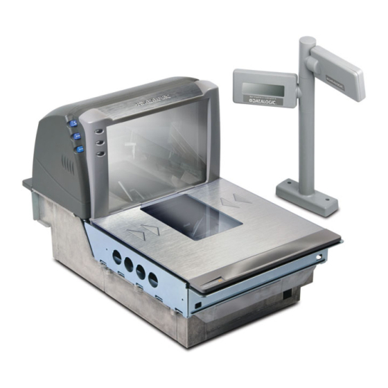
Page 56: Remote Scale Display Placement/Installation
provides physical dimensions for the AC/DC Adapter (part Figure 2-14 number 8-0599). Figure 2-14. Physical Measurements: AC/DC Adapter 2.3" (5.8 cm) Remote Scale Display Placement/Installation When installing the optional Remote Scale Display, consider both the cus- tomer’s viewing angle and the amount of daily ambient light conditions anticipated at this installation site. -
Page 57: Viewing Angle
Viewing Angle The optimum display angle is directly facing the viewer. Tilt and rotatioin adjustments can be made for the Remote Display models is shown in . To ensure that displays are easily readable for customers/ Figure 2-15 cashiers of average height, display heads should be between 48” to 60” (122 to 152 cm) from the floor. -
Page 58: Remote Display Cabling
Remote Display Cabling Your installation should also take into account the routing of Remote Dis- play cabling. Ensure that distance and obstacles spanned by the routed cable will not kink, pinch or stretch it. Also keep in mind you may need to drill a hole through which to route it. - Page 59 Figure 2-16. Model 8300RD Physical Measurements 18.5mm Dual Display Single Display 28.4mm 60mm 60mm 112mm 112mm 329mm 264mm 292.5mm 325mm 227.5mm 116.39mm 116.39mm 25.5mm 41.99mm 85.1mm 5. Feed the entire length of the Remote Scale Display interface cable through the cable routing hole so that the assembled Remote Scale Display can be positioned over the mounting screw holes.
- Page 60 Figure 2-17. Model 8300RD Remote Scale Display Mounting Mounting Example Dual Display Heads Single Display Head (optional cable routing) Figure 2-18. Model 8300RD Remote Scale Display Mounting Template 116.39mm 41.99mm 85.1mm 25.5mm 2-30 Magellan 8500Xt Scanner...
-
Page 61: Model 960Rd: Placing And Installing The Remote Scale Display
Model 960RD: Placing and Installing the Remote Scale Display (Short Pedestal Base ONLY) 1. Determine where you want to install the Remote Scale Display based on your counter design, the viewing angle and lighting con- siderations discussed previously. Reference for the dis- Figure 2-16 play’s physical dimensions. - Page 62 Figure 2-19. Model 960RD: Physical Measurements: Remote Display (Short Base) 5.6" 14.2 cm 2.75" 0.00 7.0 cm CAPACITY / CAPACITE - 30 X .01 lb / 15 x .005 kg Minimum 5.3" (13.5 cm) Maximum 11.5" (29.2 cm) 3.375" 0.953 cm 4.5"...
- Page 63 interface cable while securing the Remote Scale Display to the checkstand. Figure 2-20. Model 960RD: Remote Scale Display Components Mounting Display Head Example Cable end Display Stalk after rubberband is removed. Cable Connector Display Base (optional Interface cable Cable routing) Figure 2-21.
-
Page 64: Changing Weighing Modes
Changing Weighing Modes Your scanning-scale has been programmed for weighing in either pounds or kilograms depending upon the initial operating environment that was specified when you ordered your scanning-scale. If you need to change from pounds to kilograms or vice-versa, call Technical Support You can verify that the scale is set correctly for your country’s requirements by observing that the Remote Scale Display shows the appropriate mea-... - Page 65 4. OPTIONAL — Route your EAS antenna cable down through the checkstand cutout. (Reference your EAS controller’s set-up instructions for proper EAS antenna installation.) Figure 2-22. Connecting Cables to the Scanner/Scale 0.00 POS Terminal Remote Display Aux. Port Scale Host Power EAS Port POS TERMINAL...
-
Page 66: Installation
Installation 1. Make sure that all cables are firmly attached (except that the AC/ DC power supply should not be connected to the AC outlet yet). 2. Remove the All Weighs™ Platter to gain access to the lift han- dles. Grasp the platter as shown in and gently lift it Figure 2-24 from the scanner. - Page 67 3. Depending upon the model type, the method used to lift the unit will vary. For the first model type, hook the fingers of both hands into the lift handles located along the insides of the scanner walls, just above the debris chutes as shown in a. Other models contain lift handles that must be rotated up into position for use as shown in b.
- Page 68 Figure 2-26. Using the Bubble Level Bubble Level 6. Reinstall the All Weighs™ Platter and verify that it is flush or just below flush with the countertop. This is necessary to provide smooth scanning from either direction. Make adjustments as needed to align the platter with the counter by moving support rails up or down, or consider installing screws in positions that will allow their use in adjusting the unit’s position.
-
Page 69: System Power-Up Recap
System Power-Up Recap The System Power-Up procedure may vary depending upon the require- ments of your POS system. It is generally a good practice to power-down (switch off ) all equipment prior to connecting cables. Check with your System Supervisor and/or refer to your POS terminal manual for proper power-down and power-up procedures and interface requirements when connecting any peripheral device. - Page 70 NOTES 2-40 Magellan 8500Xt Scanner...
-
Page 71: Section 3. Operation And Maintenance
Section 3 Operation and Maintenance The information contained in this section describes how to operate and maintain the scanner, scale and EAS system. Topics include “how to’s” on scanning, EAS tag deactivation, weighing, re-zeroing the scale, removing the top cover and cleaning the upper and lower windows. Scanning Items To scan items using the scanner, slide or push them through the scan zone as shown in... -
Page 72: Proper Scanning Technique
Proper Scanning Technique The scanner was designed to provide the ultimate in ergonomic enhance- ments for Point-Of-Sale (POS) scanning. To take advantage of these advancements: Practice the techniques below to improve scanning efficiency: • Move the product across the horizontal window (See Figure 3-1 •... -
Page 73: Deactivating Security Labels
Deactivating Security Labels Two different types of Electronic Article Surveillance (EAS) systems can be optionally enabled for certain scanner models. Your system may or may not be equipped with EAS deactivation functionality. NOTE Checkpoint ® Checkpoint systems require a wired connection as shown in Figure 1-3 When this system is armed, Checkpoint EAS-tagged items are automati- cally deactivated as they are slid over the scanner’s platter area during scan-... -
Page 74: Manual Eas Deactivation Push Button
EAS Deactivation Indicators The scanner can be programmed to beep in acknowledgement of deactiva- tion or upon deactivation failure. Additionally, the tri-color indicator (the bottom-most LED) displays deactivation status. (For more information about Beeper and LED indications, see the LED/Beeper Indications & Controls section of this manual. -
Page 75: Proper Weighing Technique
Proper Weighing Technique 1. The L-shaped All-Weighs™ platter allows you to place items anywhere on its surface, including leaning against its vertical sec- tion, to be weighed accurately. The raised “Produce Rail” also provides a convenient way to ensure items do not rest on the counter or other non-weighing surfaces. -
Page 76: Operational Controls
Operational Controls The function of scanner and scale controls and indicators is listed in , LED/Beeper Indications & Controls. Turn to that appendix for Appendix A full details. Operational Modes The scanner or scanner/scale features a number of modes that are impor- tant to both the user and the system support personnel. -
Page 77: Error Reporting
Error Reporting If a fatal error is detected during Selftest or operation, the unit will not advance to Normal Operation Mode. Selftest diagnostics will cause the unit to sound a long, low tone and/or display an error message on the 7- segment display indicating where the failure occurred. -
Page 78: Operating Mode
at power-up. Removing the weight or pressing the Scale Zero Push Button should allow the scale to find zero. • When the scanner or scanner/scale completes its Selftest success- fully, it emits a tone (when configured to do so) and enters Oper- ating Mode. -
Page 79: Additional Functions
Sleep Mode After the scanner has been left idle for a preset period of time, the laser and/or motor automatically turns off (goes to sleep). This state is called Sleep Mode, and is indicated by a “slow” blink of the green light (blinking at a 2-second rate). -
Page 80: Scale Adjustments
Pressing and holding the Volume/Tone Push Button for approximately eight seconds initiates a reset, which is sounded by a rapid number of beeps. If the motor had been spinning, the lamps will blink while the motor spins down. At that point, the motor will spin back up and the scanner will continue to run the Selftest diagnostics. - Page 81 Calibrating the Scale The second adjustment, calibration, defines and sets a standard reference weight range against which all product weights are compared. If your scale is set for weighing in pounds, this range is 0 - 30 pounds, and, if your scale is set for weighing in kilograms, the range is 0 - 15 kilograms.
-
Page 82: Operational Maintenance
Operational Maintenance The scanner or scanner/scale will provide dependable service for many years. The following maintenance procedures will keep your scanner or scanner/scale operating at peak performance. Cleaning the Weigh Platter and Scan Windows Clean the exterior sur- faces of the horizontal and vertical scan windows at least twice daily with a nonabrasive, mild, water-based glass cleaner and paper towels or lint-free cleaning tissues. - Page 83 Figure 3-3. Platter Removal (Models vary) Obstruction Vertical Bezel 2. If the top edge of the platter is blocked, you may find it easier to grasp the platter vertical bezel as shown in Figure 3-3 Use caution to avoid damage to the now exposed horizontal and vertical scan windows.
- Page 84 3. The vertical scan window is held in place by two tabs each on its top and bottom edges. To remove it, carefully push out on the top as shown in and lift it out. Carefully dispose of any Figure 3-4 damaged glass.
-
Page 85: Horizontal Scan Window Replacement (Dlc)
Horizontal Scan Window Replacement (DLC) Diamond-Like Coated (DLC) horizontal scan windows are replaceable. Depending upon your model, use the appropriate instructions below. Sapphire glass does not require replacement, so it is permanently fastened in place. Do not attempt to remove Sapphire glass from the platter. NOTE 3-15 Product Reference Guide... - Page 86 Slide-in Window Models 1. Remove the All Weighs™ Platter from the scanner as shown in Figure 3-3 2. Turn the platter upside down on a clean, dry surface and remove the four screws shown in . Retain all screws for later Figure 3-5 reinstallation.
- Page 87 Gasketed Models 1. Remove the All Weighs™ Platter from the scanner as shown in Figure 3-3 2. Turn the platter upside down on a clean, dry surface and remove the two screws and two nuts shown in a. Retain all Figure 3-6 screws and nuts for later reinstallation.
- Page 88 Figure 3-6. Removing/Replacing the Gasketed DLC Window 3-18 Magellan 8500Xt Scanner...
-
Page 89: Section 4. Problem Isolation
Section 4 Problem Isolation In the event of a suspected functional problem, use the troubleshooting references provided in this section. This useful information will help you to identify and resolve the cause of the problem. The scanner/scale has a number of features that indicate when a scanner, EAS deactivation system, or scale problem occurs. -
Page 90: Diagnostic Procedures
Diagnostic Tests , for details about running diagnostic tests Chapter 2, Diagnostic Modes for the scanner and/or scale. If a problem is discovered during diagnostics, the scanner will provide feedback about the source of the problem. The remainder of this section describes these failure indications and includes troubleshooting flowcharts to help isolate the problem. -
Page 91: Error Codes
Error Codes If an error is detected, the scanner will sound a long low tone (for three seconds) and alternately flash its LEDs, indicating a failure. When this occurs, press the Volume/Tone Push button to display the error code on the 7-segment display (refer to ). -
Page 92: Error Codes/Corrective Action Table
Table 4-1. Error Codes and Corrective Action Error Probable Cause Corrective Action Code No POS interface has been selected (Null interface). See Chapter 7, Configuration to select the required interface using programming "Interface Type" Blinking barcodes. , for details about configuring the scan- Chapter 7, Programming Configuration Error ner using programming barcodes. - Page 93 Figure 4-1. 7-Segment LED Display (Models vary) 7-Segment Display Product Reference Guide...
-
Page 94: Scale Error Reporting
Scale Error Reporting Scale diagnostics uses the Remote Scale Display and the Zero Status lamp to communicate specific scale failures. The following chart shows the Remote Display messages, the Scale Status lamp indication, the problem that the scale is experiencing and what action should be taken. When troubleshooting, always remember to check all cable connections first before proceeding with other problem isolation steps. -
Page 95: Flowcharts
Flowcharts The problem isolation flowcharts on the following pages allow you to identify and troubleshoot problems with your system. Figure 4-2. Problem Isolation: Start For units using an AC/DC adapter, verify that... 1. AC power cord is connected to a functional AC outlet. 2. - Page 96 Figure 4-3. Problem Isolation: Selftest SELFTEST START Scan the Factory Does the Does the Does the Defaults bar code in 7-segment 7-segment 7-segment Section 6 to enable the display show display show display show default configuration file. Restart the unit. No interface selected (Null Interface).
- Page 97 Figure 4-4. Problem Isolation: Poor/No Reading Have you verified that all scan windows are clean and scratch-free? POOR/NO READING Before proceeding, verify that START bar code samples presented to scanner are of good quality and a symbology the scanner Enter Scanner Diagnostic Mode by can read.
- Page 98 Figure 4-5. Problem Isolation: No Transmit to POS NO TRANSMIT TO POS START Check the interface (I/F) Verify programmable cable connections. If parameters using the possible, retest the information and programming Does the system using a known- bar codes provided in Section scanner read DONE good I/F cable.
- Page 99 Figure 4-6. Problem Isolation: Scale If this is a new installation, SCALE START make sure any foam packing pieces have been removed from the scale cavity before proceeding. Lift off the platter View the Remote to verify, then set the platter Call Tech Support Display and/or the back into position.
- Page 100 Figure 4-8. Problem Isolation: Remote Display REMOTE DISPLAY Scanner-scale models that include a Remote Display when shipped START from the factory, are configured for use with the display. If you're unsure of the settings for your unit, contact Tech Support. Is the Use the programming bar unit configured...
- Page 101 Figure 4-1. Problem Isolation: EAS System NO EAS DEACTIVATION Ensure operator has been START trained in proper EAS system use (reference Chapter 3). Verify programmable Check all EAS parameters using the Does the If possible, retest the cable connections. information and programming EAS Antenna system substituting barcodes provided in Chapter...
- Page 102 NOTES 4-14 Magellan 8500Xt Scanner...
-
Page 103: Section 5. Calibration Procedures, Single Interval
Section 5 Calibration Procedures, Single Interval This section applies to scanner/scale models with single interval ONLY. NOTE A number of situations require the scale to be calibrated. They are: • at initial installation of the scanner/scale • if the scale cannot be re-zeroed •... -
Page 104: Description Of Calibration Sequence
Description of Calibration Sequence The Calibration Sequence sets the scale to an accurate reference point for weighing. This process involves the use of a Field Standard Weight Set (31.5-pounds) for calibration in pounds, (18.5-kilograms) for Metric. Once calibration has been successfully completed, the scanner/scale uses the certified weight as a reference for subsequent weighing activities. -
Page 105: Motion Test
Motion Test This test verifies that the scale will not ‘zero’ when the weighing surface of the scanner/scale is in motion. 1. Verify that the Yellow LED is on and the Remote Display reads 0.00 pounds, 0.000 pounds or 0.000 kilograms. 2. -
Page 106: Preparing The Scanner/Scale For Calibration
Preparing the Scanner/Scale for Calibration 1. Assure that the scanner/scale is stable, secure and properly installed. (Refer to , Site Preparation and Installation for Section 2 instructions on the proper installation of the scanner/scale). 2. Power-up the scanner/scale. 3. Allow the unit to reach temperature equilibrium for at least one hour. -
Page 107: Calibrating The Scale (Pounds & Kilograms)
Calibrating the Scale (Pounds & Kilograms) 1. Before proceeding, ensure that the scanner/scale has been pre- pared for this process by performing the preceding steps titled, Preparing the Scanner/Scale for Calibration 2. Remove the weigh platter and make sure that there are no obstructions in the debris chutes. - Page 108 9. When the scale is ready, the Yellow LED will begin blinking again and the display will show the message “Ad20 (add twenty pounds)” or “Ad10 (add ten kilograms).” The scanner/scale will also sound one tone if the scale is weighing in kilograms or two tones for pounds.
- Page 109 Figure 5-1. Calibration Cover & Switch or... Calibration Calibration Cover Switch Calibration Cover Calibration Switch Product Reference Guide...
-
Page 110: Calibration Verification (U.s. Pounds)
Calibration Verification (U.S. Pounds) Once you have completed the calibration sequence, you may be required to perform these step-by-step verification procedures. These procedures follow the National Institute of Standards and Technology Handbook-44 guidelines for grocery scale installations. You may be required by state or local law to have these procedures performed by a certified technician or verified by a proper official. - Page 111 Shift Test The Shift Test checks to ensure that items placed anywhere on the weigh- ing surface of the scanner/scale are weighed properly. Refer to Figure 5-2 when performing this test. 1. Place and remove in succession, a ten-pound load on the center of each of the four quadrants (1, 2, 3, and 4 in Figure 5-2) of the scanner/scale’s weigh platter.
- Page 112 Increasing- Load Test (Phase 2) After completing the Shift Test, you must complete the Increasing Load Test using 20.0, 25.0 and 30.0 pounds of weight. The upper limit of the scale is configurable according to POS interface type and may not necessarily be set at 30 pounds, which is the standard setting. For this test, continue to place weights in five pound increments only up to the upper weight limit set for your scale.
- Page 113 Decreasing-Load Test This test ensures that the scanner/scale responds properly when a heavy object is followed by a significantly smaller object. 1. Place a 30.0-pound load on the scale and verify that the display shows between 29.99 and 30.01 pounds. If the upper weight limit for your scale is not set at 30 pounds, begin by plac- ing weight equaling your upper limit setting.
-
Page 114: Calibration Verification (Kilograms)
Calibration Verification (Kilograms) Once you have completed the calibration sequence, you may be required to perform these step-by-step verification procedures. These procedures follow the National Institute of Standards and Technology Handbook-44 guidelines for grocery scale installations. You may be required by state or local law to have these procedures performed by a certified technician or verified by a proper official. - Page 115 9. Increase the weight on the scale to 7.50 kg on the center of the weighing surface and check that the display reads between 7.495 and 7.505 kg. 10. Remove the weights and verify that the display reads 0.000 kg. You have completed the Increasing-Load Test (Phase 1).
- Page 116 Figure 5-3. European Shift Test (Metric) (Models vary) Increasing- Load Test (Phase 2) After completing the Shift Test, you must complete the Increasing Load Test using 10.00, 12.50 and 15 kilograms of weight. The upper limit of the scale is configurable according to POS interface type and may not necessarily be set at 15 kilograms, which is the standard set- ting.
- Page 117 3. Place an additional 2.50 kilograms in the center of the weighing surface and check that the display reads between 14.990 kg and 15.010 kg. 4. Remove the weights and verify that the display reads 0.000 kg. 5. You have completed phase two of the increasing load test. Blanking Test This test ensures that the scanner/scale will indicate its weighing capability has been exceeded if a weight greater than 0.82 kg.
- Page 118 Decreasing-Load Test This test ensures that the scanner/scale responds properly when a heavy object is followed by a significantly smaller object. 1. Place weights that total 15.8 kilograms. If the upper weight limit for your scale is not set at 15 kilograms, begin by placing weight equaling your upper limit setting plus 0.8 kilograms.
- Page 119 Section 6 Calibration Procedures, Dual Interval This section applies to scanner/scale models with dual interval ONLY. NOTE A number of situations require the scale to be calibrated. They are: • at initial installation of the scanner/scale • if the scale cannot be rezeroed •...
- Page 120 Description of Calibration Sequence The Calibration Sequence sets the scale to an accurate reference point for weighing. This process involves the use of a Field Standard Weight Set (31.5-pounds) for calibration in pounds, (18.5-kilograms) for Metric cali- bration. Once calibration has been successfully completed, the scanner/ scale uses the certified weight as a reference for subsequent weighing activ- ities.
- Page 121 • Lead wire or paper seal (as required by law). Motion Test This test verifies that the scale will not ‘zero’ when the weighing surface of the scanner/scale is in motion. 1. Verify that the Zero lamp is On and the Remote Display reads 0.00 pounds, 0.000 pounds or 0.000 kilograms.
- Page 122 Preparing the Scanner/Scale for Calibration 1. Assure that the scanner/scale is stable. 2. Power-up the scanner/scale. 3. Allow the unit to reach temperature equilibrium for at least one hour. If the scanner/scale is already at room temperature, allow at least 15 minutes to acclimate. 4.
- Page 123 Calibrating the Scale (Pounds & Kilograms) 1. Before proceeding, ensure that the scanner/scale has been pre- pared for this process by performing the preceding steps titled, Preparing the Scanner/Scale for Calibration 2. Verify that there are no obstructions under the weigh platter. Remove the weigh platter ...
- Page 124 11. If the calibration was successful, the speaker sounds a single tone, the Scale Status LED begins blinking again, and “End-” appears in the Remote Display. 12. If the calibration was not successful, the speaker sounds five tones indicating a scale failure, and the Scale Status LED will blink twice, strobe (fast blinks), and then continually repeat this sequence until reset.
- Page 125 Figure 6-1. Calibration Cover and Switch Location or... Calibration Calibration Cover Switch Calibration Cover Calibration Switch Product Reference Guide...
-
Page 126: Increasing-Load Test (Phase 1)
Calibration Verification (Pounds) Once you have completed the calibration sequence, you may be required to perform these step-by-step verification procedures. These procedures follow the National Institute of Standards and Technology Handbook-44 guidelines for grocery scale installations. You may be required by state or local law to have these procedures performed by a cer- tified technician or verified by a proper official. -
Page 127: Shift Test
between 5.995 and 6.005. Remove the weights and verify that the display reads 0.00. 5. You have completed the Increasing-Load Test (Phase 1). Shift Test (6 Pounds) The Shift Test checks to ensure that items placed anywhere on the weigh- ing surface of the scanner/scale are weighed properly. -
Page 128: Increasing- Load Test (Phase 2)
Increasing- Load Test (Phase 2) After completing the Shift Test, you must complete the Increasing Load Test using 8.0, 10.0 and 12.0 pounds of weight. The upper limit of the scale is configurable according to the POS interface type and may not necessarily be set at 30 pounds, which is the standard setting. -
Page 129: Blanking Test
2. After verifying the accuracy of each quadrant of the weighing sur- face, remove all weight from the scale. This completes the Shift Test. Increasing- Load Test (Phase 3) After completing the Shift Test, you must complete the Increasing Load Test using 20.0, 25.0 and 30.0 pounds of weight. -
Page 130: Decreasing-Load Test
2. Verify that the display shows a dash and three hyphens (_ - - -). This is the overweight indication. The scanner/scale may blank (show an underscore and three hyphens) at any weight greater than its upper weight limit, but must blank when the upper weight limit plus 0.051 pounds are set upon the weighing sur- face. -
Page 131: Return To Zero Test
Return to Zero Test This test ensures that, after all other tests have been completed success- fully, the scanner/scale returns to zero. Remove all weights from the scale and verify that the scale reads 0.00 lb. After completing this test, close the calibration access cover and seal per local Weights and Measures requirements. -
Page 132: Increasing-Load Test (Phase 1)
If the scale fails any of these tests, go to the topic Scale Error , of this manual. Reporting Section 4, Problem Isolation NOTE Increasing-Load Test (Phase 1) This test checks scale operation for increasing loads from 0.050 kg and 3 1. - Page 133 Shift Test (Metric — 2 Kilogram) The Shift Test checks to ensure that items placed anywhere on the weigh- ing surface of the scanner/scale are weighed properly. Refer to Figure 6-3 when performing this test. 1. Place and remove, in succession, a 2 kilogram load on the center of each of the four quadrants: 2, 3, 4, and 5, and in the center (1) of the scanner/scale’s weighing platform (see ).
-
Page 134: Increasing- Load Test (Phase 2)
Increasing- Load Test (Phase 2) After completing the Shift Test, you must complete the Increasing Load Test using 4, 5 and 6 kilograms of weight. The upper limit of the scale is configurable according to POS interface type and may not neces- sarily be set at 15 kilograms, which is the standard setting. -
Page 135: Blanking Test
Increasing- Load Test (Phase 3) After completing the Shift Test, you must complete the Increasing Load Test using 10.00, 12.50 and 15 kilograms of weight. The upper limit of the scale is configurable according to POS interface type and may not neces- sarily be set at 15 kilograms, which is the standard setting. -
Page 136: Decreasing-Load Test
2. Verify that the display shows a dash and three hyphens (_---). This is the overweight indication. The scanner/scale may blank (show an underscore and three hyphens) at any weight greater than its upper limit plus 0.82 kilograms are set upon the weighing surface. NOTE Decreasing-Load Test This test ensures that the scanner/scale responds properly when a heavy... - Page 137 If the scanner/scale passes all these tests: 1. Remove the weigh platter, install the calibration switch cover and install a seal (if required). 2. Reinstall the weigh platter. If the scale fails any of these tests, turn to Section 4, Problem Isolation follow the troubleshooting ...
- Page 138 NOTES 6-20 Magellan 8500Xt Scanner...
-
Page 139: Section 7. Programming
Section 7 Programming Introduction to Label Programming The programming barcode labels contained in this manual will allow you to customize and configure features and settings for your scanner (scan- ner/scale). To ensure full compatibility and proper function, use only the programming barcodes in this manual and other product-specific publica- tions to program scanner features. -
Page 140: Customizing Your Scanner's Operation
Once you know the scanner’s current settings, you can determine what changes will be required to allow communication with your host system and/or optional features you choose to modify to customize your installa- tion. After recording the modifications needed, finish reading this section, then turn to the appropriate page and follow the instructions to program the scanner. -
Page 141: Programming Overview
The scanner can also accept programming via its auxiliary port using a handheld scanning device. Eligible handheld devices must have the ability to transmit Code 128 function codes such as the programming barcodes ® presented in this manual. Datalogic models QuickScan 1000 and ®... -
Page 142: What Is Programming Mode
What Is Programming Mode? Programming Mode is a state in which the scanner must be placed in order to accept commands via programming barcode labels. When pro- gramming using the barcode labels in this manual, the scanner is typically placed in Programming Mode by scanning the SWITCH label. While in the Programming Mode, the scanner only recognizes the special programming barcodes contained in this programming guide. -
Page 143: Programming Session
Programming Session A typical programming session is conducted as follows: 1. Scan the SWITCH barcode to place the scanner in Programming Mode. Depending upon its current programming, the scanner may emit a beep or beeps, indicating it has read the barcode and the green LED will flash on and off slowly while the scanner remains in Programming Mode. - Page 144 It is recommended that programming sessions be limited to one feature at a time. Should you make a mistake in the programming sequence, it can be difficult to discover where an error has been made if several fea- tures are programmed at once. Additionally, it can be confusing to deter- mine which features may or may not have been successfully set following NOTE such a session.
-
Page 145: Programming Sequence
Programming Sequence To modify a scanner feature (item), the programming barcodes contained in this manual must be scanned in a given sequence depending upon the feature being programmed (as shown in Table 7-1). There are three possi- ble programming sequences: If the scanner’s interface type must be changed, always be sure that inter- face configuration is the FIRST item scanned during a programming ses- sion. - Page 146 Table 7-1. Programming Sequence ITEM TAG ITEM VALUE END/RESET ENABLE NEW FEATURE SWITCH SWITCH 3 4 5 ENABLE NEW FEATURE USING THE FOLLOWING SETTINGS... SWITCH SWITCH ONE BAR CODE CONTAINS SWITCH + ITEM TAG + ITEM VALUE + SWITCH Magellan 8500Xt Scanner...
-
Page 147: Led And Beeper Indicators
LED and Beeper Indicators The scanner provides a set of indicators that verify/announce the various scanner functions. If You Make a Mistake... If, during a programming session, you find that you are unsure of the scanner’s settings or wish to reset the scanner’s configuration, use the Return to Factory Settings label below to return the scanner’s configura- tion to the factory settings. -
Page 148: Test Mode
Test Mode Use this feature to place the scanner into a testing, or “demo” mode. This special mode disables the scanner interface, meaning that barcode data is not sent out to the host via the scanner interface. This allows the barcode to be scanned continuously without requiring a response from the POS terminal. -
Page 149: General Scanner And Scale Features
General Scanner and Scale Features Double Read Timeout The Double Read Timeout feature sets a time limit that determines how much time must pass before reading the same label again (e.g. two identi- cal items in succession). To set the Double Read Timeout: 1. - Page 150 Double Read Timeout — continued Remember to cover any unused barcodes on this and the facing page to ensure that the scanner reads only the barcode you intend to scan. DOUBLE READ TIMEOUT = 800ms DOUBLE READ TIMEOUT = 1 SECOND 7-12 Magellan 8500Xt Scanner...
-
Page 151: Laser Timeout
Laser Timeout The laser timeout feature sets the time for switching the visible laser diodes (VLDs) off if the scanner is idle. Using this feature can prolong the life of the VLDs. To set the Laser Timeout: 1. Scan the SWITCH barcode. 2. - Page 152 Laser Timeout — continued Remember to cover any unused barcodes on this and the facing page to ensure that the scanner reads only the barcode you intend to scan. LASER TIMEOUT = 10 MINUTES LASER TIMEOUT = 15 MINUTES 7-14 Magellan 8500Xt Scanner...
-
Page 153: Motor Timeout
Motor Timeout The Motor Timeout feature sets the time for automatically switching the motor off when the scanner is not in use. Laser safety requires that the laser switch off before the motor. If you set the motor timeout shorter than the laser timeout, the motor and the laser will both shut off when the motor timeout expires. - Page 154 Motor Timeout — continued Remember to cover any unused barcodes on this and the facing page to ensure that the scanner reads only the barcode you intend to scan. MOTOR TIMEOUT = 10 MINUTES MOTOR TIMEOUT = 15 MINUTES 7-16 Magellan 8500Xt Scanner...
- Page 155 Motor Timeout — continued Remember to cover any unused barcodes on this and the facing page to ensure that the scanner reads only the barcode you intend to scan. MOTOR TIMEOUT = 30 MINUTES MOTOR TIMEOUT = 60 MINUTES 7-17 Product Reference Guide...
-
Page 156: Green Led Idle State
Green LED Idle State This feature specifies the state of the green scanner LED when the scanner is idle and ready to read a label. Options are: • • On dim To set the LED Idle State: 1. Scan the SWITCH barcode. 2. -
Page 157: Scanner Button Options
Scanner Button Options Configure the scanner volume button to one of the following modes of operation: • Enable all functions: Volume, tone, diagnostics and reset. • Enable only volume, tone and reset. • Enable reset only. • Disable all button functions To set the desired Scanner Button Option: 1. - Page 158 Scanner Button Options — continued Remember to cover any unused barcodes on this and the facing page to ensure that the scanner reads only the barcode you intend to scan. SCANNER BUTTON OPTION = ENABLE RESET ONLY SCANNER BUTTON OPTION = DISABLE ALL BUTTON FUNCTIONS 7-20 Magellan 8500Xt Scanner...
-
Page 159: Power-Up Beep Control
Power-up Beep Control Specifies the type of audible indication that is made when entering scan- ner-active mode on power-up. Choices are: • No beep • One beep To set the Power-up Beep: 1. Scan the SWITCH barcode. 2. Scan your selection from the barcodes below. You’ll need to cover any unused barcodes on this and the facing page to ensure that the scanner reads only the barcode you intend to scan. -
Page 160: Good Read Beep Control
Good Read Beep Control This feature enables/disables scanner beep upon successfully decoding of a label. To set this feature: 1. Scan the SWITCH barcode. 2. Scan your selection from the two barcodes below. You’ll need to cover any unused barcodes on this and the facing page to ensure that the scanner reads only the barcode you intend to scan. -
Page 161: Good Read Beep Frequency
Good Read Beep Frequency Adjusts the scanner’s good read beep to sound at low, medium, or high fre- quency (controls the beeper’s pitch/tone). • Low = 660 Hz • Medium = 860 Hz • High = 1050 Hz To set the Good Read Beep Frequency: 1. - Page 162 Good Read Beep Frequency — continued Remember to cover any unused barcodes on this and the facing page to ensure that the scanner reads only the barcode you intend to scan. GOOD READ BEEP FREQUENCY = MEDIUM GOOD READ BEEP FREQUENCY = HIGH 7-24 Magellan 8500Xt Scanner...
-
Page 163: Good Read Beep Length
Good Read Beep Length Specifies the duration of a good read beep. To set the good read beep length: 1. Scan the SWITCH barcode. 2. Scan the barcode, SET GOOD READ BEEP LENGTH. You’ll need to cover any unused barcodes on this and the facing page to ensure that the scanner reads only the barcode you intend to scan. -
Page 164: Good Read Beep Volume
Good Read Beep Volume Selects the beeper volume upon a good read beep. There are four select- able volumes, with each volume increment adding approximately five decibels to the previous level: • 0 = Lowest Volume • 1 = Low Volume •... - Page 165 Good Read Beep Volume — continued Remember to cover any unused barcodes on this and the facing page to ensure that the scanner reads only the barcode you intend to scan. GOOD READ BEEP VOLUME = LOW GOOD READ BEEP VOLUME = MEDIUM 7-27 Product Reference Guide...
- Page 166 Good Read Beep Volume — continued Remember to cover any unused barcodes on this and the facing page to ensure that the scanner reads only the barcode you intend to scan. GOOD READ BEEP VOLUME = HIGH 7-28 Magellan 8500Xt Scanner...
-
Page 167: Good Read When To Indicate
Good Read When to Indicate This feature specifies when the scanner will provide indication (beep and/ or flash its green LED) upon successfully reading a barcode. • Good Read = Indicate after decode For scanner models having intelligent integrated EAS, label transmission (and hence the good read beep) is completed after the EAS logic executes. - Page 168 Good Read When to Indicate — continued Remember to cover any unused barcodes on this and the facing page to ensure that the scanner reads only the barcode you intend to scan. GOOD READ = INDICATE AFTER DECODE GOOD READ = INDICATE AFTER TRANSMIT 7-30 Magellan 8500Xt Scanner...
- Page 169 Good Read When to Indicate — continued Remember to cover any unused barcodes on this and the facing page to ensure that the scanner reads only the barcode you intend to scan. GOOD READ = INDICATE AFTER CTS GOES INACTIVE, THEN ACTIVE (RS-232 ONLY) GOOD READ = INDICATE AFTER EACH OUTPUT STRUCTURE PROOFED 7-31...
-
Page 170: Scale Enable
Scale Enable Use this feature to enable or disable scale operation. Recalibration/recertification may be required when adding scale functional- ity. Consult your local Weights and Measures authority. If this feature is enabled the scanner will expect that it is to function as a scanner-scale, and will indicate an error if it is not a scale-equipped unit. -
Page 171: Scale Enforced Zero Return
Scale Enforced Zero Return This feature enables/disables the enforced zero return of the scale. Three settings are available for this feature: • Disable • Scale Must Return to Zero Weight Within Four Minutes — Scale will require re-zeroing if a non-zero weight is left on for more than 4 minutes •... - Page 172 Scale Enforced Zero Return — continued Remember to cover any unused barcodes on this and the facing page to ensure that the scanner reads only the barcode you intend to scan. SCALE ENFORCED ZERO RETURN = SCALE MUST RETURN TO ZERO WEIGHT WITHIN 4 MINUTES SCALE ENFORCED ZERO RETURN = SCALE MUST RETURN TO ZERO WEIGHT BETWEEN WEIGHT REQUESTS...
-
Page 173: Scale Interface Type
Scale Interface Type Use this feature to select the scale interface type for RS-232 Standard and RS-232 Wincor/Nixdorf POS interfaces. Choices are: • No Scale Interface • RS-232 — SASI • RS-232 — ICL To set the Scale Interface Type: 1. - Page 174 Scale Interface Type — continued Remember to cover any unused barcodes on this and the facing page to ensure that the scanner reads only the barcode you intend to scan. SCALE INTERFACE TYPE = RS-232 — ICL 7-36 Magellan 8500Xt Scanner...
-
Page 175: Remote Display - Enable/Disable
Remote Display — Enable/Disable The scanner-scale can be configured to operate with or without a Remote Display. Recalibration/recertification may be required when adding a Remote Display. Consult your local Weights and Measures authority. If this feature is enabled the scanner-scale will expect that it is connected to a Remote Display, and will indicate an error if one is not. -
Page 176: Aux Port Mode
(only one option can be active at a time). • Disabled — Port is inactive • External Handheld Input — Supports Datalogic handheld scanners (QuickScan 1000, QuickScan 6000, PowerScan) as well ® as other models such as the Symbol HotShot. - Page 177 Aux Port Mode — continued Remember to cover any unused barcodes on this and the facing page to ensure that the scanner reads only the barcode you intend to scan. AUX PORT MODE = EXTERNAL HANDHELD INPUT AUX PORT MODE = PIR/CT 7-39 Product Reference Guide...
-
Page 178: Laser Failure Mode
Laser Failure Mode This configuration item selects whether the scanner should continue oper- ating if only one laser is functional. (The scanner has two lasers: One for the horizontal window, and one for the vertical window.) Options for this feature are: •... -
Page 179: Productivity Index Reporting (Pir)/Cashier Training (Ct)
Productivity Index Reporting (PIR)/Cashier Training (CT) When PIR/CT is enabled, label quality data is appended to decoded data before being presented to the POS. The PIR feature allows the scanner to provide information to an external computer indicating how easy the label was to read. -
Page 180: Eas Features - Sensormatic
EAS Features — Sensormatic ® These features control the Sensormatic AMB-9010 EAS controller box. This orderable option is installed at the time of manufacture. See to set options for the Check- EAS Features — Checkpoint on page 54 ® point EAS system. - Page 181 EAS Mode — continued Remember to cover any unused barcodes on this and the facing page to ensure that the scanner reads only the barcode you intend to scan. EAS MODE = DISABLE EAS MODE = COUPLED MODE 7-43 Product Reference Guide...
- Page 182 EAS Mode — continued Remember to cover any unused barcodes on this and the facing page to ensure that the scanner reads only the barcode you intend to scan. EAS MODE = DECOUPLED MODE EAS MODE = HYBRID MODE 7-44 Magellan 8500Xt Scanner...
- Page 183 EAS Mode — continued Remember to cover any unused barcodes on this and the facing page to ensure that the scanner reads only the barcode you intend to scan. EAS MODE = HOST MODE 7-45 Product Reference Guide...
-
Page 184: Eas Beep Duration
EAS Beep Duration Sets the duration of the EAS successful deactivation beep, specified in 10ms increments. The beep only occurs if EAS mode is not disabled. To set the EAS Beep Duration: 1. Scan the SWITCH barcode. 2. Scan the barcode, below. -
Page 185: Eas Retry Count
EAS Retry Count This feature sets the number of times the deactivation sequence (defined by the feature, “EAS Deactivation Duration — Retry ”) is restarted after a failed deactivation attempt. To set the EAS Retry Count: 1. Scan the SWITCH barcode. 2. -
Page 186: Manual Eas Deactivation Push Button
Manual EAS Deactivation Push Button This feature is for use in Coupled Mode . When it is enabled, EAS deacti- vation can be manually initiated by placing the item with the EAS tag downstream of the horizontal scan window and pushing the Manual EAS Deactivation Push Button. - Page 187 Manual EAS Deactivation Push Button — continued Remember to cover any unused barcodes on this and the facing page to ensure that the scanner reads only the barcode you intend to scan. To set this feature: 1. Scan the SWITCH barcode. 2.
- Page 188 Manual EAS Deactivation Push Button — continued Remember to cover any unused barcodes on this and the facing page to ensure that the scanner reads only the barcode you intend to scan. MANUAL EAS DEACTIVATON PUSH BUTTON = ENABLE ONLY WHEN SCANNER ENABLED 7-50 Magellan...
-
Page 189: Eas Deactivation Duration - Coupled
EAS Deactivation Duration — Coupled Specifies the amount of time EAS deactivation is operative once the func- tion has been initiated following a barcode read. This setting pertains only to units configured for EAS Coupled Mode. Refer- ence the EAS Mode description for more information about Coupled and Decoupled EAS operation. -
Page 190: Eas Deactivation Duration - Retry
EAS Deactivation Duration — Retry Specifies the amount of time EAS deactivation is operative once the func- tion has been initiated following EAS tag detection (prior to barcode read). This setting pertains only to units configured for EAS Coupled Mode. Refer- ence the “EAS Mode ”... -
Page 191: Eas Deactivation Duration - Manual
EAS Deactivation Duration — Manual Specifies the amount of time EAS deactivation is operative upon pushing the Manual EAS Deactivation Push Button This setting pertains only to units configured for EAS Coupled Mode. Refer- ence the “EAS Mode ” description for more information about Coupled and Decoupled EAS operation. -
Page 192: Eas Features - Checkpoint
EAS Features — Checkpoint ® The features in this section apply only to Checkpoint EAS systems. See to set options for that system. EAS Features — Sensormatic on page 42 EAS Active State Specifies the active state polarity of EAS (Electronic Article Survellance); the inactive state is its opposite polarity. -
Page 193: Eas Timeout
EAS Timeout Specifies the amount of time that an EAS (Electronic Article Survellance) signal is held in its active state for a good read. To set the EAS Timeout: 1. Scan the SWITCH barcode. 2. Scan the barcode, below. You’ll need to cover SET EAS TIMEOUT any unused barcodes on this and the facing page to ensure that the scanner reads only the barcode you intend to scan. -
Page 194: Interface Related Features
Interface Related Features Interface Type Specifies the current scanner interface. Selections are: INTERFACE (I/F) TYPE INTERFACE (I/F) TYPE I/F I.D. NUMBER I/F I.D. NUMBER RS-232 Standard Keyboard Wedge A RS-232 Wincor-Nixdorf Keyboard Wedge B RS-232 Single Cable Keyboard Wedge C OEM USB Keyboard Wedge D Port 17... - Page 195 Interface Type — continued A new scanner may have been shipped from the factory with a Null Interface (no interface type selected) to ensure system compatibility at installation. In this case, the correct Interface Type programming barcode must be scanned first before the scanner can be used with a POS system.
- Page 196 Interface Type — continued 4. Complete the programming sequence by scanning the SWITCH barcode. Once the correct interface has been set, it will be necessary to proceed to the appropriate pages in this manual that select parameters and options for that interface.
- Page 197 RS-232 Interface Selection Remember to cover any unused barcodes on this and the facing page to ensure that the scanner reads only the barcode you intend to scan. Great care should be taken to select the correct interface type, since you can cause damage to the scanner and/or POS terminal by attempting to change to an incompatible interface.
- Page 198 RS-232 Wincor-Nixdorf Interface Selection Remember to cover any unused barcodes on this and the facing page to ensure that the scanner reads only the barcode you intend to scan. Great care should be taken to select the correct interface type, since you can cause damage to the scanner and/or POS terminal by attempting to change to an incompatible interface.
- Page 199 RS-232 Single Cable Interface Selection Remember to cover any unused barcodes on this and the facing page to ensure that the scanner reads only the barcode you intend to scan. Great care should be taken to select the correct interface type, since you can cause damage to the scanner and/or POS terminal by attempting to change to an incompatible interface.
- Page 200 OEM USB Interface Selection Remember to cover any unused barcodes on this and the facing page to ensure that the scanner reads only the barcode you intend to scan. Great care should be taken to select the correct interface type, since you can cause damage to the scanner and/or POS terminal by attempting to change to an incompatible interface.
-
Page 201: Ibm Port 17 Interface Selection
IBM Port 17 Interface Selection Remember to cover any unused barcodes on this and the facing page to ensure that the scanner reads only the barcode you intend to scan. Great care should be taken to select the correct interface type, since you can cause damage to the scanner and/or POS terminal by attempting to change to an incompatible interface. - Page 202 IBM Port 5B Interface Selection Remember to cover any unused barcodes on this and the facing page to ensure that the scanner reads only the barcode you intend to scan. Great care should be taken to select the correct interface type, since you can cause damage to the scanner and/or POS terminal by attempting to change to an incompatible interface.
- Page 203 IBM Port 9B Interface Selection Remember to cover any unused barcodes on this and the facing page to ensure that the scanner reads only the barcode you intend to scan. Great care should be taken to select the correct interface type, since you can cause damage to the scanner and/or POS terminal by attempting to change to an incompatible interface.
- Page 204 USB Keyboard Interface Selection Remember to cover any unused barcodes on this and the facing page to ensure that the scanner reads only the barcode you intend to scan. Great care should be taken to select the correct interface type, since you can cause damage to the scanner and/or POS terminal by attempting to change to an incompatible interface.
- Page 205 Keyboard Wedge A Interface Selection Remember to cover any unused barcodes on this and the facing page to ensure that the scanner reads only the barcode you intend to scan. Great care should be taken to select the correct interface type, since you can cause damage to the scanner and/or POS terminal by attempting to change to an incompatible interface.
- Page 206 Keyboard Wedge B Interface Selection Remember to cover any unused barcodes on this and the facing page to ensure that the scanner reads only the barcode you intend to scan. Great care should be taken to select the correct interface type, since you can cause damage to the scanner and/or POS terminal by attempting to change to an incompatible interface.
- Page 207 Keyboard Wedge C Interface Selection Remember to cover any unused barcodes on this and the facing page to ensure that the scanner reads only the barcode you intend to scan. Great care should be taken to select the correct interface type, since you can cause damage to the scanner and/or POS terminal by attempting to change to an incompatible interface.
- Page 208 Keyboard Wedge D Interface Selection Remember to cover any unused barcodes on this and the facing page to ensure that the scanner reads only the barcode you intend to scan. Great care should be taken to select the correct interface type, since you can cause damage to the scanner and/or POS terminal by attempting to change to an incompatible interface.
- Page 209 Keyboard Wedge E Interface Selection Remember to cover any unused barcodes on this and the facing page to ensure that the scanner reads only the barcode you intend to scan. Great care should be taken to select the correct interface type, since you can cause damage to the scanner and/or POS terminal by attempting to change to an incompatible interface.
- Page 210 Keyboard Wedge F Interface Selection Remember to cover any unused barcodes on this and the facing page to ensure that the scanner reads only the barcode you intend to scan. Great care should be taken to select the correct interface type, since you can cause damage to the scanner and/or POS terminal by attempting to change to an incompatible interface.
- Page 211 Keyboard Wedge G Interface Selection Remember to cover any unused barcodes on this and the facing page to ensure that the scanner reads only the barcode you intend to scan. Great care should be taken to select the correct interface type, since you can cause damage to the scanner and/or POS terminal by attempting to change to an incompatible interface.
- Page 212 Keyboard Wedge H Interface Selection Remember to cover any unused barcodes on this and the facing page to ensure that the scanner reads only the barcode you intend to scan. Great care should be taken to select the correct interface type, since you can cause damage to the scanner and/or POS terminal by attempting to change to an incompatible interface.
- Page 213 Keyboard Wedge I Interface Selection Remember to cover any unused barcodes on this and the facing page to ensure that the scanner reads only the barcode you intend to scan. Great care should be taken to select the correct interface type, since you can cause damage to the scanner and/or POS terminal by attempting to change to an incompatible interface.
- Page 214 Keyboard Wedge J Interface Selection Remember to cover any unused barcodes on this and the facing page to ensure that the scanner reads only the barcode you intend to scan. Great care should be taken to select the correct interface type, since you can cause damage to the scanner and/or POS terminal by attempting to change to an incompatible interface.
-
Page 215: Maximum Host-Transmitted Message Length
Maximum Host-Transmitted Message Length Specifies the maximum number of data characters allowed in messages transmitted to the host. To set the Maximum Host-Transmitted Message Length: 1. Scan the SWITCH barcode. 2. Scan the barcode, SET MAXIMUM HOST-TRANSMITTED MESSAGE LENGTH below. You’ll need to cover any unused bar- codes on this and the facing page to ensure that the scanner reads only the barcode you intend to scan. -
Page 216: Number Of Host Transmission Buffers
Number of Host Transmission Buffers Specifies the number of host transmission(s) that may be buffered. By buffering data from a barcode, the scanner can continue to read a new bar- code while the old one is being transmitted to the host. Selecting BUF- FERS = 1 means that the first barcode must be transmitted before a new one can be read. -
Page 217: Global Prefix
Global Prefix This feature applies to RS-232 interfaces (Standard, Wincor-Nixdorf, and Single Cable). It specifies the prefix that is added to beginning of label transmission. To specify the Global Prefix Character(s): 1. Scan the SWITCH barcode. 2. Scan the barcode, SET GLOBAL PREFIX below. You’ll need to cover any unused barcodes to ensure the scanner reads only the barcode you intend to scan. - Page 218 Global Prefix — continued Remember to cover any unused barcodes on this and the facing page to ensure that the scanner reads only the barcode you intend to scan. SET GLOBAL PREFIX TERMINATE SEQUENCE 7-80 Magellan 8500Xt Scanner...
-
Page 219: Global Suffix
Global Suffix This feature applies to RS-232 interfaces (Standard, Wincor-Nixdorf, and Single Cable). It specifies the suffix that is added to end of a label trans- mission. Three standard options are available below. Contact your dealer for other alternate settings for this feature. •... - Page 220 Global Suffix — continued Remember to cover any unused barcodes on this and the facing page to ensure that the scanner reads only the barcode you intend to scan. GLOBAL SUFFIX = CR GLOBAL SUFFIX = CR LF 7-82 Magellan 8500Xt Scanner...
-
Page 221: Ibm Features
IBM Features IBM Interface Options IBM interfaces offer specific control over interaction with certain devices. The OEM USB interface provides its own set of options. Refer to the feature, , in this section. OEM USB Interface Options NOTE Options for this feature are as follows: •... -
Page 222: Ibm Scale Address
IBM Scale Address This feature applies to IBM Port 17 ONLY. NOTE Specifies IBM scale address for IBM Port 17. The following three addresses are available: • • • To set the IBM Scale Address: 1. Scan the SWITCH barcode. 2. - Page 223 IBM Scale Address — continued Remember to cover any unused barcodes on this and the facing page to ensure that the scanner reads only the barcode you intend to scan. IBM SCALE ADDRESS = 6B IBM SCALE ADDRESS = 6E 7-85 Product Reference Guide...
-
Page 224: Ibm Transmit Labels In Code 39 Format
IBM Transmit Labels in Code 39 Format This feature enables/disables scanner's ability to set a symbology identifier for a specified label to Code 39 before transmitting that label data to an IBM host. This applies to: Code 128, Code 93 and Codabar for IBM Port 5B;... -
Page 225: Oem Usb Interface Options
OEM USB Interface Options The OEM-USB interface offers specific control over interaction with cer- tain devices. Options for this feature are as follows: • FULL host interface support — Accepts scanner and scale config- uration host commands. • Compatible with Magellan SL host interface support — Uses Magellan SL host interface support. - Page 226 OEM USB Interface Options — continued Remember to cover any unused barcodes on this and the facing page to ensure that the scanner reads only the barcode you intend to scan. OEM USB INTERFACE OPTION = COMPATIBLE W/MAGELLAN SL HOST I/F SUP- PORT OEM USB INTERFACE OPTION = IGNORE HOST I/F CONFIG OF SCANNER &...
-
Page 227: Oem Usb Scanner Device Type
OEM USB Scanner Device Type The OEM-USB protocol allows for the scanner to be identified as one of two different types of barcode scanners. Depending on what other scan- ners you may already have connected to a USB POS, you may need to change this setting to enable all scanners to communicate. -
Page 228: Features
RS-232 Features RS-232 Baud Rate This feature selects the baud rate required for sending and receiving data. Single cable interfaces are limited to Baud Rate selections up to 19200. They cannot communicate at Baud Rates of 38400 and up. NOTE To specify the RS-232 Baud Rate: 1. - Page 229 RS-232 Baud Rate — continued Remember to cover any unused barcodes on this and the facing page to ensure that the scanner reads only the barcode you intend to scan. RS-232 BAUD RATE = 4800 RS-232 BAUD RATE = 9600 7-91 Product Reference Guide...
- Page 230 RS-232 Baud Rate — continued Remember to cover any unused barcodes on this and the facing page to ensure that the scanner reads only the barcode you intend to scan. RS-232 BAUD RATE = 19200 RS-232 BAUD RATE = 38400 7-92 Magellan 8500Xt Scanner...
- Page 231 RS-232 Baud Rate — continued Remember to cover any unused barcodes on this and the facing page to ensure that the scanner reads only the barcode you intend to scan. RS-232 BAUD RATE = 57600 RS-232 BAUD RATE = 115200 7-93 Product Reference Guide...
-
Page 232: Number Of Data Bits
RS-232 Number of Data Bits Specifies number of data bits required for sending and receiving data. To set this feature: 1. Scan the SWITCH barcode. 2. Scan the barcode below representing the desired Data Bit setting. You’ll need to cover any unused barcodes on this and the facing page to ensure that the scanner reads only the barcode you intend to scan. -
Page 233: Number Of Stop Bits
RS-232 Number of Stop Bits Specifies number of stop bits required for sending and receiving data. To set this feature: 1. Scan the SWITCH barcode. 2. Scan the barcode below representing the desired Stop Bit setting. You’ll need to cover any unused barcodes on this and the facing page to ensure that the scanner reads only the barcode you intend to scan. -
Page 234: Parity
RS-232 Parity Specifies parity required for sending and receiving data. Options for this setting are: • RS-232 PARITY = NONE • RS-232 PARITY = EVEN • RS-232 PARITY = ODD To set this feature: 1. Scan the SWITCH barcode. 2. Scan the barcode below or on the following pages representing the desired Parity setting. - Page 235 RS-232 Parity — continued Remember to cover any unused barcodes on this and the facing page to ensure that the scanner reads only the barcode you intend to scan. RS-232 PARITY = EVEN RS-232 PARITY = ODD 7-97 Product Reference Guide...
-
Page 236: Hardware Control
RS-232 Hardware Control Enables/disables use of the RS-232 CTS signal for flow control and/or scan control. Options are: • Disable — The scanner transmits to the host regardless of any activity on the CTS line. • Enable CTS Flow Control — The CTS signal controls transmis- sion of data to the host. - Page 237 RS-232 Hardware Control — continued Remember to cover any unused barcodes on this and the facing page to ensure that the scanner reads only the barcode you intend to scan. RS-232 HARDWARE CONTROL = ENABLE CTS FLOW CONTROL RS-232 HARDWARE CONTROL = ENABLE CTS SCAN CONTROL 7-99 Product Reference Guide...
-
Page 238: Intercharacter Delay
RS-232 Intercharacter Delay Specifies delay between the end of one character and the beginning of the next in 10-millisecond increments. To set the RS-232 Intercharacter Delay: 1. Scan the SWITCH barcode. 2. Scan the barcode below, SET RS-232 INTERCHARACTER DELAY. You’ll need to cover any unused barcodes on this and the facing page to ensure that the scanner reads only the barcode you intend to scan. -
Page 239: Software Flow Control
RS-232 Software Flow Control Enables/disables RS-232 Flow Control using XON/ XOFF characters. . This item will be ignored when the feature, RS-232 NAK Character, is enabled NOTE To set this feature: 1. Scan the SWITCH barcode. 2. Scan either the enable or disable barcode below. You’ll need to cover any unused barcodes on this and the facing page to ensure that the scanner reads only the barcode you intend to scan. -
Page 240: Host Echo
RS-232 Host Echo When enabled, this feature passes all data through the scanner to the host as it comes in. This feature is used for applications where “daisy chaining” of RS-232 devices onto the same cable is necessary. If, for example, one of the devices in the chain is a terminal where someone is entering data while another person is simultaneously scanning a barcode requiring transmis- sion to the host, the scanner will wait for the RS-232 channel to be quiet... -
Page 241: Host Echo Quiet Interval
RS-232 Host Echo Quiet Interval This setting specifies the time interval of RS-232 channel inactivity which must transpire before the scanner will break the host echo loop to transmit the barcode data that has just been scanned to the host. •... -
Page 242: Ignore Host Commands
RS-232 Ignore Host Commands When set to ignore host commands, the scanner will ignore all host com- mands except for the minimum set necessary to keep the interface active, transmit labels, and transmit scale information. For normal operation of the interface, disable this feature. To set this feature: 1. -
Page 243: Ttl
RS-232 TTL Specifies whether RS-232 interface provides TTL levels on the output pins TxD and RTS. Choices are: • Normal RS-232 levels • TTL levels To set this feature: 1. Scan the SWITCH barcode. 2. Scan the barcode below which represents the desired setting for this feature. -
Page 244: Ttl Invert
RS-232 TTL Invert Enables/disables inversion of TTL. To set this feature: 1. Scan the SWITCH barcode. 2. Scan the barcode below which represents the desired setting for this feature. You’ll need to cover any unused barcodes on this and the facing page to ensure that the scanner reads only the barcode you intend to scan. -
Page 245: Beep On Ascii Bel
RS-232 Beep on ASCII BEL Enables/disables ability of scanner to beep (sound a good read tone) on receiving an ASCII BEL (07 hex). • Disable • Enable To enable/disable this feature: 1. Scan the SWITCH barcode. 2. Scan either the enable or disable barcode below. You’ll need to cover any unused barcodes on this and the facing page to ensure that the scanner reads only the barcode you intend to scan. -
Page 246: Beep After Weigh
RS-232 Beep After Weigh Enables/disables the ability of the scanner to beep after weight data is transmitted to the host. Scale interfaces that support this item are: RS-232 ICL, RS-232 SASI, and RS-232 Single Cable. To enable/disable the Beep After Weigh feature: 1. -
Page 247: Beep On Not On File
RS-232 Beep on Not on File Select for the host to beep (or not) when a not-on-file condition is detected by the host. This feature is also applicable to single cable RS-232. RS-232 BEEP ON NOT ON FILE = DISABLE ENABLE 7-109 Product Reference Guide... -
Page 248: Ack Nak Enable
RS-232 ACK NAK Enable This enables/disables the ability of the scanner to support the RS-232 ACK/NAK protocol. When configured, the scanner and/or host sends an “ACK” when it receives data properly, and sends “NAK” when the data is in error. Selections for this option are: •... - Page 249 RS-232 ACK NAK Enable — continued Remember to cover any unused barcodes on this and the facing page to ensure that the scanner reads only the barcode you intend to scan. RS-232 ACK/NAK = HOST ACKNOWLEDGEMENT RS-232 ACK/NAK = LABEL & HOST 7-111 Product Reference Guide...
-
Page 250: Ack Character
RS-232 ACK Character This feature specifies which ASCII character will be used as an ACK char- acter. DO NOT set this feature to use previously defined characters such as XON, XOFF or host commands as this will conflict with normal operation of these characters. -
Page 251: Nak Character
RS-232 NAK Character This feature specifies which ASCII character will be used as a NAK char- acter. DO NOT set this feature to use previously defined characters such as XON, XOFF or host commands as this will conflict with normal operation of these characters. -
Page 252: Retry On Ack Nak Timeout
RS-232 Retry on ACK NAK Timeout This option specifies the action scanner performs on expiration of the RS- 232 ACK NAK Timeout Value. To set this feature: 1. Scan the SWITCH barcode. 2. Scan either the enable or disable barcode below. You’ll need to cover any unused barcodes on this and the facing page to ensure that the scanner reads only the barcode you intend to scan. -
Page 253: Ack Nak Timeout Value
RS-232 ACK NAK Timeout Value This item specifies the time the scanner will wait for an ACK character from the host following a label transmission. • 0 = Infinite timeout • 1 - 75 = Timeout in 200-millisecond increments To set the ACK NAK Timeout Value: 1. -
Page 254: Ack Nak Retry Count
RS-232 ACK NAK Retry Count This feature sets the number of times for the scanner to retry a label trans- mission under a retry condition. To set the RS-232 ACK NAK Retry Count: 1. Scan the SWITCH barcode. 2. Scan the barcode, SET RS-232 ACK NAK RETRY COUNT below. -
Page 255: Ack Nak Error Handling
RS-232 ACK NAK Error Handling This item specifies the method the scanner will use to handle errors detected while waiting to receive the ACK character from the host. Errors include unrecognized host commands and communication errors such as parity or framing errors. •... - Page 256 RS-232 ACK NAK Error Handling — continued Remember to cover any unused barcodes on this and the facing page to ensure that the scanner reads only the barcode you intend to scan. RS-232 ACK NAK ERROR HANDLING = ASSUME ACK RS-232 ACK NAK ERROR HANDLING = ASSUME NAK 7-118 Magellan...
-
Page 257: Label Id Control
RS-232 Label ID Control This feature specifies whether or not Label IDs are transmitted to the host and if so, whether to attach them as a prefix or suffix. RS-232 LABEL ID CONTROL = DISABLE RS-232 LABEL ID CONTROL = ENABLE AS PREFIX 7-119 Product Reference Guide... - Page 258 RS-232 Label ID Control — continued Remember to cover any unused barcodes on this and the facing page to ensure that the scanner reads only the barcode you intend to scan. RS-232 LABEL ID CONTROL = ENABLE AS SUFFIX 7-120 Magellan 8500Xt Scanner...
-
Page 259: Single Cable Rs-232 Options
Single Cable RS-232 Options The RS-232 Single Cable interface shares some configuration options with other RS-232 interfaces. Rather than repeat them in this section as Single Cable options, please find them referenced as follows: • RS-232 Baud Rate on page 90 •... -
Page 260: Single Cable Rs-232 Scanner Only Protocol
Single Cable RS-232 Scanner Only Protocol This sets the type of interface protocol that will be used in Single Cable RS-232. Options are: • Scanner/scale RS-232 protocol • Scanner only RS-232 protocol To set this feature: 1. Scan the SWITCH barcode. 2. -
Page 261: Single Cable Rs-232 Rts Cts Selection
Single Cable RS-232 RTS CTS Selection Specifies how RTS and CTS are used to control the data flow. RTS is con- trolled by the Scanner and can be continuously held high/low, or can be asserted during label transmission. The scanner looks at CTS, as the con- figuration values state, to determine when to send label data. - Page 262 Single Cable RS-232 RTS CTS Selection — continued Remember to cover any unused barcodes on this and the facing page to ensure that the scanner reads only the barcode you intend to scan. RTS CTS SELECTION = OPTION 2 RTS CTS SELECTION = OPTION 3 7-124 Magellan 8500Xt Scanner...
- Page 263 Single Cable RS-232 RTS CTS Selection — continued Remember to cover any unused barcodes on this and the facing page to ensure that the scanner reads only the barcode you intend to scan. RTS CTS SELECTION = OPTION 4 RTS CTS SELECTION = OPTION 5 7-125 Product Reference Guide...
-
Page 264: Single Cable Rs-232 Use Bcc
Single Cable RS-232 Use BCC Enables/disables the ability of the scanner to use BCC. To set this feature: 1. Scan the SWITCH barcode. 2. Scan either the enable or disable barcode below. You’ll need to cover any unused barcodes on this and the facing page to ensure that the scanner reads only the barcode you intend to scan. -
Page 265: Single Cable Rs-232 Use Ack/Nak
Single Cable RS-232 Use ACK/NAK Enables/disables the ability of the scanner to use ACK/NAK. To set this feature: 1. Scan the SWITCH barcode. 2. Scan either the enable or disable barcode below. You’ll need to cover any unused barcodes on this and the facing page to ensure that the scanner reads only the barcode you intend to scan. -
Page 266: Single Cable Rs-232 Use Stx
Single Cable RS-232 Use STX Enables/disables the ability of the scanner to use STX. To set this feature: 1. Scan the SWITCH barcode. 2. Scan either the enable or disable barcode below. You’ll need to cover any unused barcodes on this and the facing page to ensure that the scanner reads only the barcode you intend to scan. -
Page 267: Set Single Cable Rs-232 Stx Character
Set Single Cable RS-232 STX Character This feature selects the STX character. To specify the STX Character: 1. Scan the SWITCH barcode. 2. Scan the barcode, SET SINGLE CABLE RS-232 STX CHARAC- TER below. You’ll need to cover any unused barcodes on this and the facing page to ensure the scanner reads only the barcode you intend to scan. -
Page 268: Single Cable Rs-232 Use Etx
Single Cable RS-232 Use ETX Enables/disables the ability of the scanner to use ETX. To set this feature: 1. Scan the SWITCH barcode. 2. Scan either the enable or disable barcode below. You’ll need to cover any unused barcodes on this and the facing page to ensure that the scanner reads only the barcode you intend to scan. -
Page 269: Set Single Cable Rs-232 Etx Character
Set Single Cable RS-232 ETX Character Allows selection of the ETX character. To specify the ETX Character: 1. Scan the SWITCH barcode. 2. Scan the barcode, SET SINGLE CABLE RS-232 ETX CHARAC- TER below. You’ll need to cover any unused barcodes on this and the facing page to ensure the scanner reads only the barcode you intend to scan. -
Page 270: Single Cable Rs-232 Datalogic Extensions
3. Complete the programming sequence by scanning the SWITCH barcode. SINGLE CABLE RS-232 DATALOGIC EXTENSIONS = STANDARD PROTOCOL SINGLE CABLE RS-232 DATALOGIC EXTENSIONS = SUPPORT DATALOGIC EXTENSIONS TO PROTOCOL 1. Depending upon when your scanner was purchased, this could be termed, a “PSC extension.”... -
Page 271: Symbology Programming
Symbology Programming If the scanner’s interface type must be changed, always be sure that inter- face configuration is the FIRST item scanned during a programming ses- sion. (Selecting an interface type resets ALL other configuration items — including symbology programming — to the factory default for that inter- NOTE face type.) Coupon Control... - Page 272 Coupon Control - continued Remember to cover any unused barcodes on this and the facing page to ensure that the scanner reads only the barcode you intend to scan. COUPON CONTROL = ENABLE UPC-A COUPONS COUPON CONTROL = ENABLE GS1 DATABAR EXPANDED COUPONS 7-134 Magellan 8500Xt Scanner...
-
Page 273: Upc-A Enable
UPC-A Enable Enables/disables the ability of the scanner to decode UPC-A labels. To set this feature: 1. Scan the SWITCH barcode. 2. Scan either the enable or disable barcode below. You’ll need to cover any unused barcodes on this and the facing page to ensure that the scanner reads only the barcode you intend to scan. -
Page 274: Upc-A Number System Character Transmission
UPC-A Number System Character Transmission Enables/disables transmission of a UPC-A number system character. This feature MUST be enabled for IBM interfaces for proper function. This item is ignored when the advanced feature, Full Label Edit, is enabled. NOTE To set this feature: 1. -
Page 275: Upc-A Check Character Transmission
UPC-A Check Character Transmission Enables/disables transmission of a UPC-A check character. This item is ignored when the advanced feature, Full Label Edit, is enabled. NOTE To set this feature: 1. Scan the SWITCH barcode. 2. Scan either the enable or disable barcode below. You’ll need to cover any unused barcodes on this and the facing page to ensure that the scanner reads only the barcode you intend to scan. -
Page 276: Expand Upc-A To Ean-13
Expand UPC-A to EAN-13 Enables/disables expansion of UPC-A labels to EAN/JAN-13. To set this feature: 1. Scan the SWITCH barcode. 2. Scan either the enable or disable barcode below. You’ll need to cover any unused barcodes on this and the facing page to ensure that the scanner reads only the barcode you intend to scan. -
Page 277: Upc/Ean Aim Id
UPC/EAN AIM ID This feature enables/disables transmission of the UPC/EAN AIM symbol- ogy identifier. To set this feature: 1. Scan the SWITCH barcode. 2. Scan your selection from the barcodes below. You’ll need to cover any unused barcodes on this and the facing page to ensure that the scanner reads only the barcode you intend to scan. -
Page 278: Upc-A Label Id
UPC-A Label ID This feature specifies a UPC-A label ID to be added to barcode data. The programming feature, RS-232 Label ID Control, designates whether the Label ID is transmitted as a prefix or suffix or if Label ID is disabled. NOTE To set this feature: 1. -
Page 279: Upc-A 2-Digit Supplemental Label Id
UPC-A 2-Digit Supplemental Label ID This feature specifies a UPC-A 2-Digit Supplemental label ID to be added to barcode data. The programming feature, RS-232 Label ID Control, designates whether the Label ID is transmitted as a prefix or suffix or if Label ID is dis- abled. -
Page 280: Upc-A 5-Digit Supplemental Label Id
UPC-A 5-Digit Supplemental Label ID This feature specifies a UPC-A 5-Digit Supplemental label ID to be added to barcode data. The programming feature, RS-232 Label ID Control, designates whether the Label ID is transmitted as a prefix or suffix or if Label ID is dis- abled. -
Page 281: Upc-A 128 Supplemental Label Id
UPC-A 128 Supplemental Label ID This feature specifies a UPC-A 128 Supplemental label ID to be added to barcode data. The programming feature, RS-232 Label ID Control, designates whether the Label ID is transmitted as a prefix or suffix or if Label ID is dis- abled. -
Page 282: Upc-E Enable
UPC-E Enable Enables/disables the ability of the scanner to decode UPC-E labels. To set this feature: 1. Scan the SWITCH barcode. 2. Scan either the enable or disable barcode below. You’ll need to cover any unused barcodes on this and the facing page to ensure that the scanner reads only the barcode you intend to scan. -
Page 283: Upc-E Number System Character Transmission
UPC-E Number System Character Transmission Enables/disables transmission of a UPC-E number system character. This item is ignored when the advanced feature, Full Label Edit, is enabled. NOTE To set this feature: 1. Scan the SWITCH barcode. 2. Scan either the enable or disable barcode below. You’ll need to cover any unused barcodes on this and the facing page to ensure that the scanner reads only the barcode you intend to scan. -
Page 284: Upc-E Check Character Transmission
UPC-E Check Character Transmission Enables/disables transmission of a UPC-E check character. This item is ignored when the advanced feature, Full Label Edit, is enabled. NOTE To set this feature: 1. Scan the SWITCH barcode. 2. Scan either the enable or disable barcode below. You’ll need to cover any unused barcodes on this and the facing page to ensure that the scanner reads only the barcode you intend to scan. -
Page 285: Expand Upc-E To Upc-A
Expand UPC-E to UPC-A Enables/disables expansion of UPC-E labels to UPC-A. To set this feature: 1. Scan the SWITCH barcode. 2. Scan either the enable or disable barcode below. You’ll need to cover any unused barcodes on this and the facing page to ensure that the scanner reads only the barcode you intend to scan. -
Page 286: Expand Upc-E To Ean-13
Expand UPC-E to EAN-13 Enables/disables expansion of UPC-E labels to EAN/JAN-13. To set this feature: 1. Scan the SWITCH barcode. 2. Scan either the enable or disable barcode below. You’ll need to cover any unused barcodes on this and the facing page to ensure that the scanner reads only the barcode you intend to scan. -
Page 287: Upc-E Label Id
UPC-E Label ID This feature specifies a UPC-E label ID to be added to barcode data. The programming feature, RS-232 Label ID Control, designates whether the Label ID is transmitted as a prefix or suffix or if Label ID is disabled. NOTE To set this feature: 1. -
Page 288: Upc-E 2-Digit Supplemental Label Id
UPC-E 2-Digit Supplemental Label ID This feature specifies a UPC-E 2-Digit Supplemental label ID to be added to barcode data. The programming feature, RS-232 Label ID Control, designates whether the Label ID is transmitted as a prefix or suffix or if Label ID is dis- abled. -
Page 289: Upc-E 5-Digit Supplemental Label Id
UPC-E 5-Digit Supplemental Label ID This feature specifies a UPC-E 5-Digit Supplemental label ID to be added to barcode data. The programming feature, RS-232 Label ID Control, designates whether the Label ID is transmitted as a prefix or suffix or if Label ID is disabled. NOTE To set this feature: 1. -
Page 290: Upc-E 128 Supplemental Label Id
UPC-E 128 Supplemental Label ID This feature specifies a UPC-E 128 Supplemental label ID to be added to barcode data. The programming feature, RS-232 Label ID Control, designates whether the Label ID is transmitted as a prefix or suffix or if Label ID is dis- abled. -
Page 291: Enable
EAN-13 Enable Enables/disables the ability of the scanner to decode EAN/JAN-13 labels. To set this feature: 1. Scan the SWITCH barcode. 2. Scan either the enable or disable barcode below. You’ll need to cover any unused barcodes on this and the facing page to ensure that the scanner reads only the barcode you intend to scan. -
Page 292: First Character Transmission
EAN-13 First Character Transmission Enables/disables transmission of EAN/JAN-13 first character. This item is ignored when the advanced feature, Full Label Edit, is enabled. NOTE To set this feature: 1. Scan the SWITCH barcode. 2. Scan either the enable or disable barcode below. You’ll need to cover any unused barcodes on this and the facing page to ensure that the scanner reads only the barcode you intend to scan. -
Page 293: Check Character Transmission
EAN-13 Check Character Transmission Enables/disables transmission of an EAN/JAN-13 check character. This item is ignored when the advanced feature, Full Label Edit, is enabled. NOTE To set this feature: 1. Scan the SWITCH barcode. 2. Scan either the enable or disable barcode below. You’ll need to cover any unused barcodes on this and the facing page to ensure that the scanner reads only the barcode you intend to scan. -
Page 294: Isbn Conversion Enable
EAN-13 ISBN Conversion Enable Enables/disables conversion of EAN/JAN-13 labels starting with 978 to Bookland ISBN labels. To set this feature: 1. Scan the SWITCH barcode. 2. Scan either the enable or disable barcode below. You’ll need to cover any unused barcodes on this and the facing page to ensure that the scanner reads only the barcode you intend to scan. -
Page 295: Ean 13 Label Id
EAN 13 Label ID This feature specifies an EAN 13 label ID to be added to barcode data. To set this feature: The programming feature, RS-232 Label ID Control, designates whether the Label ID is transmitted as a prefix or suffix or if Label ID is dis- abled. -
Page 296: 2-Digit Supplemental Label Id
EAN-13 2-Digit Supplemental Label ID This feature specifies an EAN-13 2-Digit Supplemental label ID to be added to barcode data. The programming feature, RS-232 Label ID Control, designates whether the Label ID is transmitted as a prefix or suffix or if Label ID is disabled. NOTE To set this feature: 1. -
Page 297: 5-Digit Supplemental Label Id
EAN-13 5-Digit Supplemental Label ID This feature specifies an EAN-13 5-Digit Supplemental label ID to be added to barcode data. The programming feature, RS-232 Label ID Control, designates whether the Label ID is transmitted as a prefix or suffix or if Label ID is dis- abled. -
Page 298: 128 Supplemental Label Id
EAN-13 128 Supplemental Label ID This feature specifies an EAN-13 128 Supplemental label ID to be added to barcode data. The programming feature, RS-232 Label ID Control, designates whether the Label ID is transmitted as a prefix or suffix or if Label ID is dis- abled. -
Page 299: Bookland Aim Id
Bookland AIM ID This feature enables/disables transmission of the Bookland AIM symbol- ogy identifier. To set this feature: 1. Scan the SWITCH barcode. 2. Scan your selection from the barcodes below. You’ll need to cover any unused barcodes on this and the facing page to ensure that the scanner reads only the barcode you intend to scan. -
Page 300: Bookland Label Id
Bookland Label ID This feature specifies a Bookland label ID to be added to barcode data. The programming feature, RS-232 Label ID Control, designates whether the Label ID is transmitted as a prefix or suffix or if Label ID is dis- abled. -
Page 301: Enable
EAN-8 Enable Enables/disables the ability of the scanner to decode EAN/JAN-8 labels. To set this feature: 1. Scan the SWITCH barcode. 2. Scan either the enable or disable barcode below. You’ll need to cover any unused barcodes on this and the facing page to ensure that the scanner reads only the barcode you intend to scan. -
Page 302: Check Character Transmission
EAN-8 Check Character Transmission Enables/disables transmission of an EAN/JAN-8 check character. This item is ignored when the advanced feature, Full Label Edit, is enabled. NOTE To set this feature: 1. Scan the SWITCH barcode. 2. Scan either the enable or disable barcode below. You’ll need to cover any unused barcodes on this and the facing page to ensure that the scanner reads only the barcode you intend to scan. -
Page 303: Expand Ean-8 To Ean-13
Expand EAN-8 to EAN-13 Enables/disables expansion of EAN/JAN-8 labels to EAN/JAN-13. To set this feature: 1. Scan the SWITCH barcode. 2. Scan either the enable or disable barcode below. You’ll need to cover any unused barcodes on this and the facing page to ensure that the scanner reads only the barcode you intend to scan. -
Page 304: Ean 8 Label Id
EAN 8 Label ID This feature specifies an EAN 8 label ID to be added to barcode data. To set this feature: The programming feature, RS-232 Label ID Control, designates whether the Label ID is transmitted as a prefix or suffix or if Label ID is disabled. NOTE To set this feature: 1. -
Page 305: 2-Digit Supplemental Label Id
EAN-8 2-Digit Supplemental Label ID This feature specifies an EAN-8 2-Digit Supplemental label ID to be added to barcode data. The programming feature, RS-232 Label ID Control, designates whether the Label ID is transmitted as a prefix or suffix or if Label ID is disabled. NOTE To set this feature: 1. -
Page 306: 5-Digit Supplemental Label Id
EAN-8 5-Digit Supplemental Label ID This feature specifies an EAN-8 5-Digit Supplemental label ID to be added to barcode data. The programming feature, RS-232 Label ID Control, designates whether the Label ID is transmitted as a prefix or suffix or if Label ID is dis- abled. -
Page 307: 128 Supplemental Label Id
EAN-8 128 Supplemental Label ID This feature specifies an EAN-8 128 Supplemental label ID to be added to barcode data. The programming feature, RS-232 Label ID Control, designates whether the Label ID is transmitted as a prefix or suffix or if Label ID is dis- abled. -
Page 308: Decoding Levels
EAN-8 Decoding Levels Decoding levels allow the decoder to be set to perform at one of four selectable levels: • Very Conservative — Slower scan time, virtually eleminates mis- reads. The most secure setting. • Slightly More Aggressive — Faster scanning, more aggressive, yet minimizes misreads. - Page 309 EAN-8 Decoding Levels — continued Remember to cover any unused barcodes on this and the facing page to ensure that the scanner reads only the barcode you intend to scan. EAN-8 DECODING LEVELS = VERY CONSERVATIVE EAN-8 DECODING LEVELS = SLIGHTLY MORE AGGRESSIVE 7-171 Product Reference Guide...
- Page 310 EAN-8 Decoding Levels — continued Remember to cover any unused barcodes on this and the facing page to ensure that the scanner reads only the barcode you intend to scan. EAN-8 DECODING LEVELS = MODERATELY AGGRESSIVE EAN-8 DECODING LEVELS = VERY AGGRESSIVE 7-172 Magellan 8500Xt Scanner...
-
Page 311: Other Upc/Ean Options
Other UPC/EAN Options The following pages contain other selectable features for UPC/EAN sym- bologies: • UPC/EAN Reconstruction • Price Weight Check • Enable EAN Two Label • Addons • UPC-A and EAN-13 Decoding Levels 7-173 Product Reference Guide... -
Page 312: Upc/Ean Reconstruction
UPC/EAN Reconstruction Enables/disables the ability of the scanner to decode a class of UPC/EAN labels with voids. The label voids may be caused by printing defects or physical damage. This feature may be helpful in environments with in- store printed labels. Enabling this feature increases the potential of misreads. -
Page 313: Price Weight Check
Price Weight Check Enables/disables calculation and verification of price/weight check digits. Applies to all UPC-A and EAN/JAN-13 labels with eligible Number Sys- tem/First Character digits. Options are: • Disable • 4-digit price/weight • 5-digit price/weight • 4-digit European price/weight • 5-digit European price/weight To set this feature: 1. - Page 314 Price Weight Check — continued Remember to cover any unused barcodes on this and the facing page to ensure that the scanner reads only the barcode you intend to scan. PRICE WEIGHT CHECK = 4-DIGIT PRICE/WEIGHT PRICE WEIGHT CHECK = 5-DIGIT PRICE/WEIGHT 7-176 Magellan 8500Xt Scanner...
- Page 315 Price Weight Check — continued Remember to cover any unused barcodes on this and the facing page to ensure that the scanner reads only the barcode you intend to scan. PRICE WEIGHT CHECK = 4-DIGIT EUROPEAN PRICE/WEIGHT PRICE WEIGHT CHECK = 5-DIGIT EUROPEAN PRICE/WEIGHT 7-177 Product Reference Guide...
-
Page 316: Enable Ean Two Label
Enable EAN Two Label Enables/disables the ability of the scanner to decode EAN two-label pairs. To set this feature: 1. Scan the SWITCH barcode. 2. Scan either the enable or disable barcode below. You’ll need to cover any unused barcodes on this and the facing page to ensure that the scanner reads only the barcode you intend to scan. -
Page 317: Addons
Addons The scanner is capable of processing different types of addon codes, including: • 2-Digit Supplemental • 5-Digit Supplemental Options are provided on the following pages for your convenience: • Disable all addons — The scanner will not look for or read addons. •... - Page 318 Addons — continued Remember to cover any unused barcodes on this and the facing page to ensure that the scanner reads only the barcode you intend to scan. ADDONS = OPTIONAL 2-DIGIT AND 5-DIGIT SUPPLEMENTAL 7-180 Magellan 8500Xt Scanner...
-
Page 319: Upc-A And Ean-13 Decoding Levels
UPC-A and EAN-13 Decoding Levels Decoding levels allow the decoder to be set to perform at one of four selectable levels: • Very Conservative — Slower scan time, virtually eleminates mis- reads. The most secure setting. • Slightly More Aggressive — Faster scanning, more aggressive, yet minimizes misreads. - Page 320 UPC-A and EAN-13 Decoding Levels — continued Remember to cover any unused barcodes on this and the facing page to ensure that the scanner reads only the barcode you intend to scan. UPC-A/EAN-13 DECODING LEVELS = VERY CONSERVATIVE UPC-A/EAN-13 DECODING LEVELS = SLIGHTLY MORE AGGRESSIVE 7-182 Magellan 8500Xt Scanner...
- Page 321 UPC-A and EAN-13 Decoding Levels — continued Remember to cover any unused barcodes on this and the facing page to ensure that the scanner reads only the barcode you intend to scan. UPC-A/EAN-13 DECODING LEVELS = MODERATELY AGGRESSIVE UPC-A/EAN-13 DECODING LEVELS = VERY AGGRESSIVE 7-183 Product Reference Guide...
-
Page 322: Gtin Enable
GTIN Enable Enables/Disables the ability to convert UPCE, UPCA, EAN8, and EAN13 labels into the GTIN 14-character format. If add-on information is present on the base label prior to the conversion taking place, the add-on information will be appended to the converted GTIN barcode. -
Page 323: Gtin Label Id
GTIN Label ID This feature specifies a GTIN label ID to be added to barcode data when GTIN conversion is enabled. The programming feature, RS-232 Label ID Control, designates whether the Label ID is transmitted as a prefix or suffix or if Label ID is disabled. NOTE To set this feature: 1. -
Page 324: Gtin 2-Digit Supplemental Label Id
GTIN 2-Digit Supplemental Label ID This feature specifies a GTIN label ID to be added to barcode data when GTIN conversion is enabled and 2-digit supplemental addon barcode labels are converted. The programming feature, RS-232 Label ID Control, designates whether the Label ID is transmitted as a prefix or suffix or if Label ID is disabled. -
Page 325: Gtin 5-Digit Supplemental Label Id
GTIN 5-Digit Supplemental Label ID This feature specifies a GTIN label ID to be added to barcode data when GTIN conversion is enabled and 5-digit supplemental addon barcode labels are converted. The programming feature, RS-232 Label ID Control, designates whether the Label ID is transmitted as a prefix or suffix or if Label ID is disabled. -
Page 326: Gtin Code 128 Supplemental Label Id
GTIN Code 128 Supplemental Label ID This feature specifies a GTIN label ID to be added to barcode data when GTIN conversion is enabled and Code 128 supplemental addon barcode labels are converted The programming feature, RS-232 Label ID Control, designates whether the Label ID is transmitted as a prefix or suffix or if Label ID is disabled. -
Page 327: Databar Omnidirectional Enable
DataBar Omnidirectional Enable Enables/disables the ability of the scanner to decode DataBar Omnidirec- tional labels. This value-added feature is a factory-programmed option. Contact your dealer for information about upgrading your system to include this advanced capability. NOTE To set this feature: 1. -
Page 328: Databar Omnidirectional Check Character Transmission
DataBar Omnidirectional Check Character Transmission Enables/disables transmission of the DataBar Omnidirectional check character. To set this feature: 1. Scan the SWITCH barcode. 2. Scan either the enable or disable barcode below. You’ll need to cover any unused barcodes on this and the facing page to ensure that the scanner reads only the barcode you intend to scan. -
Page 329: Databar Omnidirectional/Ean-128 Emulation
DataBar Omnidirectional/EAN-128 Emulation Enables/disables the ability of DataBar Omnidirectional to be transmitted as EAN-128. To set this feature: 1. Scan the SWITCH barcode. 2. Scan either the enable or disable barcode below. You’ll need to cover any unused barcodes on this and the facing page to ensure that the scanner reads only the barcode you intend to scan. -
Page 330: Databar Omnidirectional 2D Component Enable
DataBar Omnidirectional 2D Component Enable When this feature is enabled, the software will not decode an DataBar Omnidirectional barcode with a 2D component associated with it, and the 2D component will be discarded. To set this feature: 1. Scan the SWITCH barcode. 2. -
Page 331: Databar Omnidirectional Aim Id
DataBar Omnidirectional AIM ID This feature enables/disables transmission of the DataBar Omnidirec- tional AIM symbology identifier. To set this feature: 1. Scan the SWITCH barcode. 2. Scan your selection from the barcodes below. You’ll need to cover any unused barcodes on this and the facing page to ensure that the scanner reads only the barcode you intend to scan. -
Page 332: Databar Omnidirectional Label Id
DataBar Omnidirectional Label ID This feature specifies an DataBar Omnidirectional label ID to be added to barcode data. To set this feature: The programming feature, RS-232 Label ID Control, designates whether the Label ID is transmitted as a prefix or suffix or if Label ID is dis- abled. -
Page 333: Databar Expanded Enable
DataBar Expanded Enable Enables/disables the ability of the scanner to decode DataBar Expanded labels. This value-added feature is a factory-programmed option. Contact your dealer for information about upgrading your system to include this advanced capability. NOTE To set this feature: 1. -
Page 334: Databar Expanded Ean-128 Emulation
DataBar Expanded EAN-128 Emulation Enables/disables EAN 128 emulation for DataBar Expanded. To set this feature: 1. Scan the SWITCH barcode. 2. Scan either the enable or disable barcode below. You’ll need to cover any unused barcodes on this and the facing page to ensure that the scanner reads only the barcode you intend to scan. -
Page 335: Databar Expanded 2D Component Enable
DataBar Expanded 2D Component Enable When this feature is enabled, the software will not decode an DataBar Expanded barcode with a 2D component associated with it, and the 2D component will be discarded. To set this feature: 1. Scan the SWITCH barcode. 2. -
Page 336: Databar Expanded Aim Id
DataBar Expanded AIM ID This feature enables/disables transmission of the DataBar Expanded AIM symbology identifier. To set this feature: 1. Scan the SWITCH barcode. 2. Scan your selection from the barcodes below. You’ll need to cover any unused barcodes on this and the facing page to ensure that the scanner reads only the barcode you intend to scan. -
Page 337: Databar Expanded Label Id
DataBar Expanded Label ID This feature specifies an DataBar Expanded label ID to be added to bar- code data. The programming feature, RS-232 Label ID Control, designates whether the Label ID is transmitted as a prefix or suffix or if Label ID is dis- abled. -
Page 338: Databar Expanded Length Control
DataBar Expanded Length Control This feature specifies either variable-length or fixed-length decoding for DataBar Expanded. To set this feature: 1. Scan the SWITCH barcode. 2. Scan your selection from the barcodes below. You’ll need to cover any unused barcodes on this and the facing page to ensure that the scanner reads only the barcode you intend to scan. -
Page 339: Databar Expanded Length 1
DataBar Expanded Length 1 If DataBar Expanded Length Control is set to Fixed-Length decoding, this feature specifies DataBar Expanded first fixed length. If DataBar Expanded Length Control is set to Variable-Length decoding, this feature specifies the minimum label length. To set this feature: 1. -
Page 340: Databar Expanded Length 2
DataBar Expanded Length 2 If DataBar Expanded Length Control is set to Fixed-Length decoding, this feature specifies DataBar Expanded second fixed length. If DataBar Expanded Length Control is set to Variable-Length decoding, this feature specifies the maximum label length. When in Fixed Length mode, if Length 2 is set to the value of 00 (zero), then only Length 1 will apply. -
Page 341: Code 39 Enable
Code 39 Enable Enables/disables the ability of the scanner to decode Code 39 labels. To set this feature: 1. Scan the SWITCH barcode. 2. Scan either the enable or disable barcode below. You’ll need to cover any unused barcodes on this and the facing page to ensure that the scanner reads only the barcode you intend to scan. -
Page 342: Code 39 Start Stop Character Transmission
Code 39 Start Stop Character Transmission Enables/disables transmission of Code 39 start and stop characters. This item is ignored when the advanced feature, Full Label Edit, is enabled. NOTE To set this feature: 1. Scan the SWITCH barcode. 2. Scan either the enable or disable barcode below. You’ll need to cover any unused barcodes on this and the facing page to ensure that the scanner reads only the barcode you intend to scan. -
Page 343: Code 39 Check Character Calculation
Code 39 Check Character Calculation Enables/disables calculation and verification of an optional Code 39 check character. When disabled, any check character in label is treated as a data character. If check calculation is disabled, the risk is increased that a misread can occur. -
Page 344: Code 39 Check Character Transmission
Code 39 Check Character Transmission Enables/disables transmission of optional Code 39 check character. This item is ignored when the advanced feature, Full Label Edit, is enabled. NOTE To set this feature: 1. Scan the SWITCH barcode. 2. Scan either the enable or disable barcode below. You’ll need to cover any unused barcodes on this and the facing page to ensure that the scanner reads only the barcode you intend to scan. -
Page 345: Code 39 Full Ascii
Code 39 Full ASCII Enables/disables the ability of the scanner to translate to Code 39 full ASCII labels. To set this feature: 1. Scan the SWITCH barcode. 2. Scan either the enable or disable barcode below. You’ll need to cover any unused barcodes on this and the facing page to ensure that the scanner reads only the barcode you intend to scan. -
Page 346: Code 39 Aim Id
Code 39 AIM ID This feature enables/disables transmission of the Code 39 AIM symbology identifier. To set this feature: 1. Scan the SWITCH barcode. 2. Scan your selection from the barcodes below. You’ll need to cover any unused barcodes on this and the facing page to ensure that the scanner reads only the barcode you intend to scan. -
Page 347: Code 39 Label Id
Code 39 Label ID This feature specifies a Code 39 label ID to be added to barcode data. The programming feature, RS-232 Label ID Control, designates whether the Label ID is transmitted as a prefix or suffix or if Label ID is dis- abled. -
Page 348: Code 39 Length Control
Code 39 Length Control This feature specifies whether variable-length or fixed-length decoding will be set for Code 39. To set this feature: 1. Scan the SWITCH barcode. 2. Scan your selection from the barcodes below. You’ll need to cover any unused barcodes on this and the facing page to ensure that the scanner reads only the barcode you intend to scan. -
Page 349: Code 39 Length 1
Code 39 Length 1 If Code 39 Length Control is set to Fixed-Length decoding, this feature specifies Code 39 first fixed length. If Code 39 Length Control is set to Variable-Length decoding, this feature specifies the minimum label length. To set this feature: 1. -
Page 350: Code 39 Length 2
Code 39 Length 2 If Code 39 Length Control is set to Fixed-Length decoding, this feature specifies Code 39 second fixed length. If Code 39 Length Control is set to Variable-Length decoding, this feature specifies the maximum label length. When in Fixed Length mode, if Length 2 is set to the value of 00, then only Length 1 will apply NOTE To set this feature:... -
Page 351: Code 39 Stitching
Code 39 Stitching Enables/disables stitching for Code 39 labels. When parts of a Code 39 barcode are presented to the scanner with this feature enabled, the barcode parts will be assembled by the scanner’s software, and the data will be decoded if all barcode proofing requirements are met. -
Page 352: Code 32 Enable
Code 32 Enable Enables/disables the ability of the scanner to decode Italian Pharmaceuti- cal Code 32 labels. To set this feature: 1. Scan the SWITCH barcode. 2. Scan either the enable or disable barcode below. You’ll need to cover any unused barcodes on this and the facing page to ensure that the scanner reads only the barcode you intend to scan. -
Page 353: Code 32 Start Stop Character Transmission
Code 32 Start Stop Character Transmission Enables/ disables transmission of start and stop characters for Code 32. This item is ignored when the advanced feature, Full Label Edit, is enabled. NOTE To set this feature: 1. Scan the SWITCH barcode. 2. -
Page 354: Code 32 Check Character Transmission
Code 32 Check Character Transmission Enables/disables transmission of Code 32 check character. This item is ignored when the advanced feature, Full Label Edit, is enabled. NOTE To set this feature: 1. Scan the SWITCH barcode. 2. Scan either the enable or disable barcode below. You’ll need to cover any unused barcodes on this and the facing page to ensure that the scanner reads only the barcode you intend to scan. -
Page 355: Code 32 Label Id
Code 32 Label ID This feature specifies a Code 32 label ID to be added to barcode data. The programming feature, RS-232 Label ID Control, designates whether the Label ID is transmitted as a prefix or suffix or if Label ID is dis- abled. -
Page 356: Code 128 Enable
Code 128 Enable Enables/disables the ability of the scanner to decode Code 128 labels. To set this feature: 1. Scan the SWITCH barcode. 2. Scan either the enable or disable barcode below. You’ll need to cover any unused barcodes on this and the facing page to ensure that the scanner reads only the barcode you intend to scan. -
Page 357: Code 128 Transmit Function Characters
Code 128 Transmit Function Characters Enables/disables transmission of Code 128 function characters 1, 2, 3, and 4. Disabled is the recommended setting for all interfaces. NOTE To set this feature: 1. Scan the SWITCH barcode. 2. Scan either the enable or disable barcode below. You’ll need to cover any unused barcodes on this and the facing page to ensure that the scanner reads only the barcode you intend to scan. -
Page 358: Convert Code128 To Code 39
Convert Code128 to Code 39 Enables/disables conversion of Code 128 labels to Code 39. To set this feature: 1. Scan the SWITCH barcode. 2. Scan either the enable or disable barcode below. You’ll need to cover any unused barcodes on this and the facing page to ensure that the scanner reads only the barcode you intend to scan. -
Page 359: Code 128 Aim Id
Code 128 AIM ID This feature enables/disables transmission of the Code 128 AIM symbol- ogy identifier. To set this feature: 1. Scan the SWITCH barcode. 2. Scan your selection from the barcodes below. You’ll need to cover any unused barcodes on this and the facing page to ensure that the scanner reads only the barcode you intend to scan. -
Page 360: Code 128 Label Id
Code 128 Label ID This feature specifies a Code 128 label ID to be added to barcode data.. The programming feature, RS-232 Label ID Control, designates whether the Label ID is transmitted as a prefix or suffix or if Label ID is dis- abled. -
Page 361: Code 128 Length Control
Code 128 Length Control This feature specifies whether variable-length or fixed-length decoding will be set for Code 128. To set this feature: 1. Scan the SWITCH barcode. 2. Scan your selection from the barcodes below. You’ll need to cover any unused barcodes on this and the facing page to ensure that the scanner reads only the barcode you intend to scan. -
Page 362: Code 128 Length 1
Code 128 Length 1 If Code 128 Length Control is set to Fixed-Length decoding, this feature specifies Code 128 first fixed length. If Code 128 Length Control is set to Variable-Length decoding, this feature specifies the minmum label length. To set this feature: 1. -
Page 363: Code 128 Length 2
Code 128 Length 2 If Code 128 Length Control is set to Fixed-Length decoding, this feature specifies Code 128 second fixed length. If Code 128 Length Control is set to Variable-Length decoding, this feature specifies the maximum label length. When in Fixed Length mode, if Length 2 is set to the value of 00 (zero), then only Length 1 will apply. -
Page 364: Code 128 Stitching
Code 128 Stitching Enables/disables stitching for Code 128 labels. When parts of a Code 128 barcode are presented to the scanner with this feature enabled, the barcode parts will be assembled by the scanner’s software, and the data will be decoded if all barcode proofing requirements are met. -
Page 365: Enable
EAN-128 Enable Enables/disables the ability of the scanner to decode EAN-128 labels. To set this feature: 1. Scan the SWITCH barcode. 2. Scan either the enable or disable barcode below. You’ll need to cover any unused barcodes on this and the facing page to ensure that the scanner reads only the barcode you intend to scan. -
Page 366: Ean 128 Aim Id
EAN 128 AIM ID This feature enables/disables transmission of the EAN 128 AIM symbol- ogy identifier. To set this feature: 1. Scan the SWITCH barcode. 2. Scan your selection from the barcodes below. You’ll need to cover any unused barcodes on this and the facing page to ensure that the scanner reads only the barcode you intend to scan. -
Page 367: Ean 128 Label Id
EAN 128 Label ID This feature specifies an EAN 128 label ID to be added to barcode data.. The programming feature, RS-232 Label ID Control, designates whether the Label ID is transmitted as a prefix or suffix or if Label ID is dis- abled. -
Page 368: Interleaved 2 Of 5 (I 2 Of 5) Enable
Interleaved 2 of 5 (I 2 OF 5) Enable Enables/disables the ability of the scanner to decode Interleaved 2 of 5 labels. To set this feature: 1. Scan the SWITCH barcode. 2. Scan either the enable or disable barcode below. You’ll need to cover any unused barcodes on this and the facing page to ensure that the scanner reads only the barcode you intend to scan. -
Page 369: I 2 Of 5 Check Character Calculation
I 2 of 5 Check Character Calculation Enables/disables calculation and verification of an optional Interleaved 2 of 5 check character. If check character calculation is disabled, the risk is increased that a mis- read can occur. When disabled, any check characters in a barcode are treated as data characters. -
Page 370: I 2 Of 5 Check Character Transmission
I 2 of 5 Check Character Transmission Enables/disables transmission of an optional Interleaved 2 of 5 check char- acter. This feature applies only when I 2 of 5 Check Character Calculation is enabled. This item is ignored when the advanced feature, Full Label Edit, is enabled. -
Page 371: I 2 Of 5 Aim Id
I 2 of 5 AIM ID This feature enables/disables transmission of the I 2 of 5 AIM symbology identifier. To set this feature: 1. Scan the SWITCH barcode. 2. Scan your selection from the barcodes below. You’ll need to cover any unused barcodes on this and the facing page to ensure that the scanner reads only the barcode you intend to scan. -
Page 372: I 2 Of 5 Label Id
I 2 of 5 Label ID This feature specifies an I 2 of 5 label ID to be added to barcode data.. The programming feature, RS-232 Label ID Control, designates whether the Label ID is transmitted as a prefix or suffix or if Label ID is dis- abled. -
Page 373: I 2 Of 5 Length Control
I 2 of 5 Length Control This feature specifies whether variable-length or fixed-length decoding will be set for I 2 of 5. To set this feature: 1. Scan the SWITCH barcode. 2. Scan your selection from the barcodes below. You’ll need to cover any unused barcodes on this and the facing page to ensure that the scanner reads only the barcode you intend to scan. -
Page 374: I 2 Of 5 Length 1
I 2 of 5 Length 1 If I 2 of 5 Length Control is set to Fixed-Length decoding, this feature specifies I 2 of 5 first fixed length. If I 2 of 5 Length Control is set to Vari- able-Length decoding, this feature specifies the minimum label length. To set this feature: 1. -
Page 375: I 2 Of 5 Length 2
I 2 of 5 Length 2 If I 2 of 5 Length Control is set to Fixed-Length decoding, this feature specifies I 2 of 5 second fixed length. If I 2 of 5 Length Control is set to Variable-Length decoding, this feature specifies the maximum label length. -
Page 376: I 2 Of 5 Stitching
I 2 of 5 Stitching Enables/disables stitching for I 2 of 5 labels. When parts of an I 2 of 5 bar- code are presented to the scanner with this feature enabled, the barcode parts will be assembled by the scanner’s software, and the data will be decoded if all barcode proofing requirements are met. -
Page 377: Codabar Enable
Codabar Enable Enables/disables the ability of the scanner to decode Codabar labels. To set this feature: 1. Scan the SWITCH barcode. 2. Scan either the enable or disable barcode below. You’ll need to cover any unused barcodes on this and the facing page to ensure that the scanner reads only the barcode you intend to scan. -
Page 378: Codabar Start Stop Character Transmission
Codabar Start Stop Character Transmission Enables/disables transmission of Codabar start and stop characters. This item is ignored when the advanced feature, Full Label Edit, is enabled. NOTE To set this feature: 1. Scan the SWITCH barcode. 2. Scan either the enable or disable barcode below. You’ll need to cover any unused barcodes on this and the facing page to ensure that the scanner reads only the barcode you intend to scan. -
Page 379: Codabar Start Stop Character Set
Codabar Start Stop Character Set This feature selects the format of transmitted Codabar start/stop charac- ters. Options are: • ABCD/TN* E • ABCD/ABCD • abcd/tn* e • abcd/abcd To set this feature: 1. Scan the SWITCH barcode. 2. Scan the barcode below or from the following page representing the desired option. - Page 380 Codabar Start Stop Character Set — continued Remember to cover any unused barcodes on this and the facing page to ensure that the scanner reads only the barcode you intend to scan. CODABAR START STOP CHARACTER = abcd/tn* e CODABAR START STOP CHARACTER = abcd/abcd 7-242 Magellan 8500Xt Scanner...
-
Page 381: Codabar Start Stop Character Match
Codabar Start Stop Character Match Enables/disables the requirement that start and stop characters match. To set this feature: 1. Scan the SWITCH barcode. 2. Scan either the enable or disable barcode below. You’ll need to cover any unused barcodes on this and the facing page to ensure that the scanner reads only the barcode you intend to scan. -
Page 382: Codabar Check Character Calculation
Codabar Check Character Calculation Enables/disables calculation and verification of an optional Codabar check character If check character calculation is disabled, the risk is increased that a mis- read can occur. When disabled, any check characters in a barcode are treated as data characters. NOTE To set this feature: 1. -
Page 383: Codabar Check Character Transmission
Codabar Check Character Transmission Enables/disables transmission of an optional Codabar check character. Applies only when Codabar Check Character Calculation is enabled. This item is ignored when the advanced feature, Full Label Edit, is enabled. NOTE To set this feature: 1. Scan the SWITCH barcode. 2. -
Page 384: Codabar Aim Id
Codabar AIM ID This feature enables/disables transmission of the Codabar AIM symbology identifier. To set this feature: 1. Scan the SWITCH barcode. 2. Scan your selection from the barcodes below. You’ll need to cover any unused barcodes on this and the facing page to ensure that the scanner reads only the barcode you intend to scan. -
Page 385: Codabar Label Id
Codabar Label ID This feature specifies a Codabar label ID to e added to barcode data. The programming feature, RS-232 Label ID Control, designates whether the Label ID is transmitted as a prefix or suffix or if Label ID is dis- abled. -
Page 386: Codabar Length Control
Codabar Length Control This feature specifies whether variable-length or fixed-length decoding will be set for Codabar. To set this feature: 1. Scan the SWITCH barcode. 2. Scan your selection from the barcodes below. You’ll need to cover any unused barcodes on this and the facing page to ensure that the scanner reads only the barcode you intend to scan. -
Page 387: Codabar Length 1
Codabar Length 1 If Codabar Length Control is set to Fixed-Length decoding, this feature specifies Codabar first fixed length. If Codabar Length Control is set to Variable-Length decoding, this feature specifies the minimum label length. To set this feature: 1. Scan the SWITCH barcode. 2. -
Page 388: Codabar Length 2
Codabar Length 2 If Codabar Length Control is set to Fixed-Length decoding, this feature specifies Codabar second fixed length. If Codabar Length Control is set to Variable-Length decoding, this feature specifies the maximum label length. When in Fixed Length mode, if Length 2 is set to the value of 00 (zero), then only Length 1 will apply. -
Page 389: Codabar Stitching
Codabar Stitching Enables/disables stitching for Codabar labels. When parts of a Codabar barcode are presented to the scanner with this feature enabled, the barcode parts will be assembled by the scanner’s software, and the data will be decoded if all barcode proofing requirements are met. To set this feature: 1. -
Page 390: Code 93 Enable
Code 93 Enable Enables/disables the ability of the scanner to decode Code 93 labels. To set this feature: 1. Scan the SWITCH barcode. 2. Scan either the enable or disable barcode below. You’ll need to cover any unused barcodes on this and the facing page to ensure that the scanner reads only the barcode you intend to scan. -
Page 391: Code 93 Aim Id
Code 93 AIM ID This feature enables/disables transmission of the Code 93 AIM symbology identifier. To set this feature: 1. Scan the SWITCH barcode. 2. Scan your selection from the barcodes below. You’ll need to cover any unused barcodes on this and the facing page to ensure that the scanner reads only the barcode you intend to scan. -
Page 392: Code 93 Label Id
Code 93 Label ID This feature specifies a Code 93 label ID to be added to barcode data.. The programming feature, RS-232 Label ID Control, designates whether the Label ID is transmitted as a prefix or suffix or if Label ID is dis- abled. -
Page 393: Code 93 Length Control
Code 93 Length Control This feature specifies whether variable-length or fixed-length decoding will be set for Code 93. To set this feature: 1. Scan the SWITCH barcode. 2. Scan your selection from the barcodes below. You’ll need to cover any unused barcodes on this and the facing page to ensure that the scanner reads only the barcode you intend to scan. -
Page 394: Code 93 Length 1
Code 93 Length 1 If Code 93 Length Control is set to Fixed-Length decoding, this feature specifies Code 93 first fixed length. If Code 93 Length Control is set to Variable-Length decoding, this feature specifies the minimum label length. To set this feature: 1. -
Page 395: Code 93 Length 2
Code 93 Length 2 If Code 93 Length Control is set to Fixed-Length decoding, this feature specifies Code 93 second fixed length. If Code 93 Length Control is set to Variable-Length decoding, this feature specifies the maximum label length. When in Fixed Length mode, if Fixed Length 2 is set to the value of 00 (zero), then only Length 1 will apply. -
Page 396: Code 93 Stitching
Code 93 Stitching Enables/disables stitching for Code 93 labels. When parts of a Code 93 barcode are presented to the scanner with this feature enabled, the barcode parts will be assembled by the scanner’s software, and the data will be decoded if all barcode proofing requirements are met. -
Page 397: Msi/Plessey Enable
MSI/Plessey Enable Enables/disables the ability of the scanner to decode MSI/Plessey labels. To set this feature: 1. Scan the SWITCH barcode. 2. Scan either the enable or disable barcode below. You’ll need to cover any unused barcodes on this and the facing page to ensure that the scanner reads only the barcode you intend to scan. -
Page 398: Msi/Plessey Check Character Calculation
MSI/Plessey Check Character Calculation Enables/disables calculation and verification of optional MSI/Plessey check characters. If check character calculation is disabled, the risk is increased that a mis- read can occur. When disabled, any check characters in a barcode are treated as data characters. NOTE To set this feature: 1. -
Page 399: Msi/Plessey Number Of Check Characters
MSI/Plessey Number of Check Characters Specifies number of MSI/Plessey check characters to be calculated and verified. Check characters are always modulus 10. NOTE To set this feature: 1. Scan the SWITCH barcode. 2. Scan the barcode below representing the desired number of MSI/ Plessey check characters to be calculated and verified. -
Page 400: Msi/Plessey Check Character Transmission
MSI/Plessey Check Character Transmission Enables/disables transmission of optional MSI/Plessey check characters. This feature applies only when MSI/Plessey Check Character Calcu- lation is enabled. This item is ignored when the advanced feature, Full Label Edit, is enabled. NOTE To set this feature: 1. -
Page 401: Msi/Plessey Aim Id
MSI/Plessey AIM ID This feature enables/disables transmission of the MSI/Plessey AIM sym- bology identifier. To set this feature: 1. Scan the SWITCH barcode. 2. Scan your selection from the barcodes below. You’ll need to cover any unused barcodes on this and the facing page to ensure that the scanner reads only the barcode you intend to scan. -
Page 402: Msi/Plessey Label Id
MSI/Plessey Label ID This feature specifies an MSI/Plessey label ID to be added to barcode data. The programming feature, RS-232 Label ID Control, designates whether the Label ID is transmitted as a prefix or suffix or if Label ID is dis- abled. -
Page 403: Msi/Plessey Length Control
MSI/Plessey Length Control This feature specifies whether variable-length or fixed-length decoding will be set for MSI/Plessey. To set this feature: 1. Scan the SWITCH barcode. 2. Scan your selection from the barcodes below. You’ll need to cover any unused barcodes on this and the facing page to ensure that the scanner reads only the barcode you intend to scan. -
Page 404: Msi/Plessey Length 1
MSI/Plessey Length 1 If MSI/Plessey Length Control is set to Fixed-Length decoding, this fea- ture specifies MSI/Plessey first fixed length. If MSI/Plessey Length Con- trol is set to Variable-Length decoding, this feature specifies the minimum label length. To set this feature: 1. -
Page 405: Msi/Plessey Length 2
MSI/Plessey Length 2 If MSI/Plessey Length Control is set to Fixed-Length decoding, this fea- ture specifies MSI/Plessey second fixed length. If MSI/Plessey Length Control is set to Variable-Length decoding, this feature specifies the maxi- mum label length. When in Fixed Length mode, if Length 2 is set to the value 00 (zero), then only Length 1 will apply. -
Page 406: Msi/Plessey Stitching
MSI/Plessey Stitching Enables/disables stitching for MSI/Plessey labels. When parts of an MSI/ Plessey barcode are presented to the scanner with this feature enabled, the barcode parts will be assembled by the scanner’s software, and the data will be decoded if all barcode proofing requirements are met. To set this feature: 1. -
Page 407: Standard 2 Of 5 Enable
Standard 2 of 5 Enable Enables/disables the ability of the scanner to decode Standard 2 of 5 labels. To set this feature: 1. Scan the SWITCH barcode. 2. Scan either the enable or disable barcode below. You’ll need to cover any unused barcodes on this and the facing page to ensure that the scanner reads only the barcode you intend to scan. -
Page 408: Standard 2 Of 5 Check Character Calculation
Standard 2 of 5 Check Character Calculation Enables/disables calculation and verification of an optional Standard 2 of 5 check character. If check character calculation is disabled, the risk is increased that a mis- read can occur. When disabled, any check character in a barcode is treated as data character. -
Page 409: Standard 2 Of 5 Check Character Transmission
Standard 2 of 5 Check Character Transmission Enables/disables transmission of an optional Standard 2 of 5 check charac- ter. This feature applies only when Standard 2 of 5 Check Charac- ter Calculation is enabled. This item is ignored when the advanced feature, Full Label Edit, is enabled. -
Page 410: Standard 2 Of 5 Aim Id
Standard 2 of 5 AIM ID This feature enables/disables transmission of the Standard 2 of 5 AIM symbology identifier. To set this feature: 1. Scan the SWITCH barcode. 2. Scan your selection from the barcodes below. You’ll need to cover any unused barcodes on this and the facing page to ensure that the scanner reads only the barcode you intend to scan. -
Page 411: Standard 2 Of 5 Label Id
Standard 2 of 5 Label ID This feature specifies an Standard 2 of 5 label ID to be added to barcode data. The programming feature, RS-232 Label ID Control, designates whether the Label ID is transmitted as a prefix or suffix or if Label ID is disabled. -
Page 412: Standard 2 Of 5 Length Control
Standard 2 of 5 Length Control This feature specifies whether variable-length or fixed-length decoding will be set for 2 of 5. Standard To set this feature: 1. Scan the SWITCH barcode. 2. Scan your selection from the barcodes below. You’ll need to cover any unused barcodes on this and the facing page to ensure that the scanner reads only the barcode you intend to scan. -
Page 413: Standard 2 Of 5 Length 1
Standard 2 of 5 Length 1 If Standard 2 of 5 Length Control is set to Fixed-Length decoding, this feature specifies Standard 2 of 5 first fixed length. If Standard 2of 5 Length Control is set to Variable-Length decoding, this feature specifies the minimum label length. -
Page 414: Standard 2 Of 5 Length 2
Standard 2 of 5 Length 2 If Standard 2 of 5 Length Control is set to Fixed-Length decoding, this feature specifies Standard 2 of 5 second fixed length. If Standard 2of 5 Length Control is set to Variable-Length decoding, this feature specifies the maximum label length. -
Page 415: Standard 2 Of 5 Stitching
Standard 2 of 5 Stitching Enables/disables stitching for Standard 2 of 5 labels. When parts of a Stan- dard 2 of 5 barcode are presented to the scanner with this feature enabled, the barcode parts will be assembled by the scanner’s software, and the data will be decoded if all barcode proofing requirements are met. - Page 416 NOTES 7-278 Magellan 8500Xt Scanner...
-
Page 417: Appendix A. Led/Beeper Indications & Controls
Appendix A LED/Beeper Indications & Controls shows the operator’s controls and indicators. The descriptions Figure A-1 following identify the use or function of each component. Your model may not contain all the controls and indicators listed in this appendix. Figure A-1. Scanner and Scale Controls Volume/Tone Push Button Green LED... -
Page 418: Controls And Indicators
Controls and Indicators The control panel consists of three indicator LEDs and three push buttons as described in the following pages. The unit also includes a beeper which can be configured to sound indications of scanning, weighing, and deacti- vation activities. Since beeper indications are configurable, your unit may not be pro- grammed to sound all the indications listed. - Page 419 Table 1-1. Scanner and Scale LED Indications DURATION COMMENT INDICATION Scanner (Green) LED 1-second off, 1/ Host Disabled Host has disabled scanning. 10-second on Serves notice that a fatal FRU failure has been Audible low tone 1 second. Field Replace- detected.
- Page 420 Deactivator LED The Deactivator LED (tri-color, bottom-most) designates EAS deactiva- tion status (see ). The table also provides information about spe- Table 1-2 cial beeper indications which can be sounded in response to changes in deactivation status. Table 1-2. EAS Indications EAS DEACTIVATION DISABLED INDICATION LED DURATION...
- Page 421 Table 1-2. EAS Indications COUPLED MODE ONLY The EAS antenna Good read beep fol- Deactivation (Tri-color) LED has been triggered lows deactivation. flashes Red, then Orange, Deactivation ON to deactivate a then returns to Green. Indicated label following suc- cessful barcode read.
-
Page 422: Volume/Tone Push Button
Table 1-2. EAS Indications HYBRID MODE Deactivation (Tri-color) LED High frequency beep An EAS tag has flashes Red, then Orange, Deactivation been successfully then returns to Green. Indicated deactivated. a. Additionally, the FRU LED (7-segment display located in the bottom of the optic cavity — visi- ble through the horizontal scan window) blinks the number ‘9’. - Page 423 Table 1-3. Volume/Tone Push Button Functions (Continued) PRESS FUNCTION COMMENT DURATION Press the push button for approximately 2 seconds, Hold, then release then release. Each time this is done, the beeper will when the beeper Increments tone sound at one of three tones. Stop when the desired sounds tone (high, medium or low) is sounded.
-
Page 424: Manual Eas Deactivation Push Button
Manual EAS Deactivation Push Button Using the programming barcodes contained in Chapter 7, Programming the button can be configured to operate always, or only function when the scanner is enabled. PRESS FUNCTION COMMENT DURATION Manually initiates EAS Place the item with the EAS tag downstream of the hori- Momentary deactivation... -
Page 425: Scale Zero Push Button
Scale Zero Push Button The Scale Zero Push Button is used for multiple functions as listed in Table 1-4 The Scale Zero Push Button has no function in a “scanner only” model. NOTE Table 1-4. Scale Zero Push Button Functions PRESS FUNCTION COMMENT... - Page 426 Calibration Switch This switch initiates the scale’s calibration routine. A certified weight set is needed to perform the scale calibration steps detailed in Chapter 5, Calibra- . This switch is not included in scanners tion Procedures, Single Interval without scale modules. Calibration Switch Seal This seal allows you to secure the Calibration Switch access cover and restrict access to the Calibration Switch.
-
Page 427: Calibration Switch
Figure A-2. Calibration Switch Cover or... Calibration Calibration Cover Switch Calibration Cover Calibration Switch A-11 Product Reference Guide... - Page 428 A-12 Magellan 8500Xt Scanner...
-
Page 429: Appendix B. Cable Information
Appendix B Cable Information Introduction The following pages contain pinout information, enabling you to create standard interface cables for use in interconnecting the scanner, scale, external handheld scanner, and POS terminal. General Specifications Wire Requirements • Cable length should not exceed 15 feet. •... -
Page 430: Cable Pinout
RS-232 Cable Pinout Scanner Connector Hardware RJ45, 10 Position Cable Pinout Table 2-1RS-232 Cable Pinouts PIN # FUNCTION DESCRIPTION No Connection CTS in Clear To Send (input) No Connection RTS out Request To Send (output) RxD in Receive Data (Input) TxD out Transmit Data (output) No Connection... -
Page 431: Scale
RS-232 Cable Pinout — continued Scale Connector Hardware RJ45, 10 Position Cable Pinout Table 2-2RS-232 Scale Cable Pinouts PIN # FUNCTION DESCRIPTION +5V pullup +5V pullup CTS IN Clear To Send (input) No Connection RTS OUT Request To Send (output) RxD IN Receive Data (Input) TxD OUT... -
Page 432: Ibm Cable Pinout
IBM Cable Pinout Scanner and Scale Connector Hardware RJ45, 10 Position Cable Pinout Table 2-3IBM Cable Pinouts PIN # FUNCTION DESCRIPTION No Connection No Connection No Connection LINEB Line B No Connection LINEA Line A No Connection No Connection Signal Ground No Connection Magellan 8500Xt Scanner... -
Page 433: Scanner And Scale
OEM USB Cable Pinout Scanner and Scale Connector Hardware RJ45, 10 Position Cable Pinout Table B-4 OEM USB Cable Pinouts PIN # FUNCTION DESCRIPTION No Connection No Connection No Connection USB D- USB D- No Connection USB D+ USB D+ No Connection No Connection Signal Ground... -
Page 434: Auxilliary Port
Auxilliary Port External Handheld Input Connector Hardware RJ45, 10 Position Cable Pinout Table 2-5Auxilliary Port Cable Pinouts PIN # FUNCTION DESCRIPTION +5V pullup +5V pullup CTS in Clear To Send (input) No Connection - Reserved RTS out Request To Send (output) RxD in Receive Data (Input) TxD out... -
Page 435: Power Cable
Power Cable Connector Hardware 6 pin Molex Cable Pinout Table 2-6Power Cable Pinouts PIN # FUNCTION DESCRIPTION EARTH GND Earth Ground SIGNAL GND Signal Ground +5V IN +5V in No Connection No Connection +12V IN +12V in Product Reference Guide... -
Page 436: Remote Display
Remote Display Connector Hardware 4 pin SDL Cable Pinout Table 2-7Remote Display Cable Pinouts PIN # FUNCTION DESCRIPTION +12V OUT +12V out LINE_A_DSPLY LINE A Display LINE_B_DSPLY LINE B Display Ground Magellan 8500Xt Scanner... -
Page 437: Eas Comm Port - Sensormatic
EAS Comm Port — Sensormatic EAS Deactivator Control Box Connection Connector Hardware RJ10 Cable Pinout Table 2-8EAS Comm Port Cable Pinouts PIN # FUNCTION DESCRIPTION VCC5 VCC5 EAS DEACT EN~ EAS Deactivation VCC5 VCC5 EAS DETECT EN~ EAS Detection EAS LBL DETECT EN~ EAS tag Detect Signal Ground No Connection... -
Page 438: Eas Interlock Connector - Checkpoint
EAS Interlock Connector — Checkpoint Antenna Connections. Connect ONLY using approved cables approved by the manufacturer for this product. NOTE Connector Hardware RJ-4 Cable Pinout Table B-9 PIN # SIGNAL +5V Out EAS Out Speaker Out a. The “Speaker Out” line is an analog signal (5Vpp max), connected to one of the internal speaker termi- nals, intended to connect to an external amplifier to drive an external speaker. -
Page 439: Appendix C Keypad
Appendix C Keypad Use the barcodes in this section to enter numbers and characters as you would select digits/characters from a keypad. Scan your selection from the barcodes below. You’ll need to cover any unused barcodes on this and the facing page to ensure that the scanner reads only the barcode you intend to scan. - Page 440 Use the barcodes in this section to enter numbers and characters as you would select digits/characters from a keypad. Scan your selection from the barcodes below. You’ll need to cover any unused barcodes on this and the facing page to ensure that the scanner reads only the barcode you intend to scan.
- Page 441 Use the barcodes in this section to enter numbers and characters as you would select digits/characters from a keypad. Scan your selection from the barcodes below. You’ll need to cover any unused barcodes on this and the facing page to ensure that the scanner reads only the barcode you intend to scan.
- Page 442 Use the barcodes in this section to enter numbers and characters as you would select digits/characters from a keypad. Scan your selection from the barcodes below. You’ll need to cover any unused barcodes on this and the facing page to ensure that the scanner reads only the barcode you intend to scan.
- Page 443 Use the barcodes in this section to enter numbers and characters as you would select digits/characters from a keypad. Scan your selection from the barcodes below. You’ll need to cover any unused barcodes on this and the facing page to ensure that the scanner reads only the barcode you intend to scan.
- Page 444 Use the barcodes in this section to enter numbers and characters as you would select digits/characters from a keypad. Scan your selection from the barcodes below. You’ll need to cover any unused barcodes on this and the facing page to ensure that the scanner reads only the barcode you intend to scan.
- Page 445 Use the barcodes in this section to enter numbers and characters as you would select digits/characters from a keypad. Scan your selection from the barcodes below. You’ll need to cover any unused barcodes on this and the facing page to ensure that the scanner reads only the barcode you intend to scan.
- Page 446 Use the barcodes in this section to enter numbers and characters as you would select digits/characters from a keypad. Scan your selection from the barcodes below. You’ll need to cover any unused barcodes on this and the facing page to ensure that the scanner reads only the barcode you intend to scan.
-
Page 447: Appendix D Host Commands
Appendix D Host Commands Accepting Commands from an RS-232 Scanner Host The scanner responds to the following RS-232 commands: COMMAND ASCII COMMENT Enable Scanner 0x45 Disable Scanner 0x44 Reset Scanner 0x52 Not On File Indication 0x46 Long series of beeps Beep Good Read Tone 0x42 Beeps if Good Read Beep is enabled... - Page 448 NOTES Magellan 8500Xt Scanner...
-
Page 449: Appendix E Factory Defaults
Appendix E Factory Defaults The following table provides a listing of the most common factory settings for the interfaces shown. Table 5-1. Factory Default Settings Wincor- Single RS-232 IBM 17 OEM USB Nixdorf Cable Double Read Time- (600ms) (600ms) (600ms) (600ms) (600ms) (600ms) - Page 450 Wincor- Single RS-232 IBM 17 OEM USB Nixdorf Cable Scale Enforced Zero 0 (disable) 0 (disable) 0 (disable) 0 (disable) 0 (disable) 0 (disable) Return 7 (RS-232 4 (RS-232 4 (RS-232 4 (RS-232 1 (IBM Scale Interface Type single (OEM SASI) SASI) SASI)
- Page 451 Wincor- Single RS-232 IBM 17 OEM USB Nixdorf Cable Maximum Host- Transmitted Mes- 0 (no limit) 0 (no limit) 0 (no limit) 0 (no limit) 0 (no limit) 0 (no limit) sage Length Number of Host Transmission Buffers (2 buffers) (2 buffers) (2 buffers) (2 buffers)
- Page 452 Wincor- Single RS-232 IBM 17 OEM USB Nixdorf Cable RS-232 Ignore Host 0 (disable) 0 (disable) 0 (disable) 0 (disable) 0 (disable) 0 (disable) Commands 0 (normal 0 (normal RS-232 TTL RS-232) RS-232) RS-232 TTL Invert 0 (disable) 0 (disable) RS-232 Beep on 0 (disable) 0 (disable)
- Page 453 232 STX Character Single Cable RS-232 1 (enable) Use ETX Set Single Cable RS- 13 (CR) 232 ETX Character Single Cable RS-232 0 (std Datalogic Extensions protocol) UPC-A Enable 1 (enable) 1 (enable) 1 (enable) 1 (enable) 1 (enable) 1 (enable)
- Page 454 Wincor- Single RS-232 IBM 17 OEM USB Nixdorf Cable UPC-A 128 Supple- 4100("A") 4100("A") 4100("A") 4100("A") mental Label ID UPC-E Enable 1 (enable) 1 (enable) 1 (enable) 1 (enable) 1 (enable) 1 (enable) UPC-E Number Sys- tem Character Trans- 1 (enable) 1 (enable) 1 (enable) 1 (enable)
- Page 455 Wincor- Single RS-232 IBM 17 OEM USB Nixdorf Cable EAN-13 5-Digit Sup- 4600("F") 4600("F") 4100("A") 4600("F") plemental Label ID EAN-13 128 Supple- 4600("F") 4600("F") 4100("A") 4600("F") mental Label ID Bookland AIM ID 0 (disable) 0 (disable) 0 (disable) Bookland Label ID 4900 ("I") 4900 ("I") 4100 ("A")
- Page 456 Wincor- Single RS-232 IBM 17 OEM USB Nixdorf Cable GTIN Label ID 4700 (“G”) 4700 (“G”) 4700 (“G”) 4700 (“G”) GTIN 2-Digit Supple- 4700 (“G”) 4700 (“G”) 4700 (“G”) 4700 (“G”) mental Label ID GTIN 5-Digit Supple- 4700 (“G”) 4700 (“G”) 4700 (“G”) 4700 (“G”) mental Label ID...
- Page 457 Wincor- Single RS-232 IBM 17 OEM USB Nixdorf Cable DataBar Expanded 5258 5258 5258 4500 ("E") Label ID ("RX") ("RX") ("RX") DataBar Expanded Length Control (variable) (variable) (variable) (variable) (variable) (variable) DataBar Expanded 8 Fixed 8 Fixed 8 Fixed 8 Fixed 8 Fixed 8 Fixed Length 1...
- Page 458 Wincor- Single RS-232 IBM 17 OEM USB Nixdorf Cable Code 32 Start Stop Character Transmis- 0 (disable) 0 (disable) 0 (disable) 0 (disable) 0 (disable) 0 (disable) sion Code 32 Check Char- 1 (enable) 1 (enable) 1 (enable) 1 (enable) 1 (enable) acter Transmission Code 32 Label ID...
- Page 459 Wincor- Single RS-232 IBM 17 OEM USB Nixdorf Cable I 2 of 5 Check Char- 1 (enable) 1 (enable) 1 (enable) 1 (enable) 1 (enable) 1 (enable) acter Transmission I 2 of 5 AIM ID 0 (disable) 0 (disable) 0 (disable) 4232 I 2 of 5 Label ID 6900 ("i")
- Page 460 Wincor- Single RS-232 IBM 17 OEM USB Nixdorf Cable Codabar Length 1 14 Fixed 14 Fixed 14 Fixed 14 Fixed 14 Fixed 14 Fixed Codabar Length 2 50 Max 50 Max 50 Max 50 Max 50 Max 50 Max Codabar Stitching 0 (disable) 0 (disable) 0 (disable)
- Page 461 Wincor- Single RS-232 IBM 17 OEM USB Nixdorf Cable MSI/Plessey Length 7 Fixed 7 Fixed 7 Fixed 7 Fixed 4 Min 4 Min 4 Min 4 Min MSI/Plessey Length 8 Fixed 8 Fixed 8 Fixed 8 Fixed 16 Max 16 Max 16 Max 16 Max MSI/Plessey Stitch-...
- Page 462 NOTES E-14 Magellan 8500Xt Scanner...
-
Page 463: Appendix F. Handheld Data Format Requirements
Maximum label lengths will be enforced for label validation (i.e. labels longer than the maximum label size will not be validated). • Standard Datalogic formats generally use a single prefix character. The specific formats are provided below. Product Reference Guide... -
Page 464: Datalogic Handheld Data Format Requirements
Datalogic Handheld Data Format Requirements The following sections describe label transmission formats that are typi- cally observed in factory configurations of Datalogic handheld scanners. DataBar Omnidirectional • Prefix must be ASCII characters ‘R4’ • Check character must be included in label •... - Page 465 UPC-A with 5-Digit Supplemental • Number system must be included in label data • Check digit must be included in label data and is assumed to be correct • Prefix must be an ASCII character 'A' - total length including prefix must be 18 •...
- Page 466 UPC-E with 2-Digit Supplemental • Number system must be included in label data. • Check digit must be included in label data and is assumed to be correct. • Supplemental data is appended to base label. • Prefix must be an ASCII character 'E' - total length including pre- fix must be 11.
- Page 467 EAN-8 • Check digit must be included in label data and is assumed to be correct • Prefix must be an ASCII characters 'FF' - total length including prefix must be 10 • Example: 'FF00210126' EAN-8 with 2-Digit Supplemental • Check digit must be included in label data and is assumed to be correct.
- Page 468 EAN-13 • Check digit must be included in label data and is assumed to be correct • Prefix must be an ASCII character 'F'- total length including pre- fix must be 14 • Example: 'F1101234567891' EAN-13 with 2-Digit Supplemental • Check digit must be included in label data and is assumed to be correct •...
- Page 469 Code 39 • Check character must be included in label data. • Label length including start, stop and check characters and excluding prefix character must meet requirements imposed by the main scanner's fixed or variable label length control for this symbology type.
- Page 470 Codabar • Check character must be included in label data. • Label length including check character and excluding prefix char- acter must meet requirements imposed by the main scanner's fixed or variable label length control for this symbology type. • Prefix must be an ASCII character '%'.
-
Page 471: Aim Formats
MSI/Plessey • Check character must be included in label data. • Label length including check character and excluding prefix char- acter must meet requirements imposed by the main scanner's fixed or variable label length control for this symbology type. • Prefix must be an ASCII character '@'. -
Page 472: Digit Supplemental
• Example: ']E00060992011187'. UPC-E • AIM does not specify UPC-E as a separate symbology using this transmission format - labels will be transmitted as EAN-13. • Example: ']E00000000998875'. EAN-13 • Check digit must be included in label data and is assumed to be correct. -
Page 473: Product Reference Guide
5-Digit Supplemental • Supplemental data is appended to any EAN base label. • Prefix must be ASCII characters ']E2'. • Length of supplemental data including prefix must be 8. Total required length is 24 for EAN-13 and 19 for EAN-8. •... - Page 474 Code 39 • Check character must be included in label data. • Label length including start, stop and check characters and excluding prefix characters must meet requirements imposed by the main scanner's fixed or variable label length control for this symbology type.
- Page 475 Code 93 • Prefix must be ASCII characters ']G0'. • Label length excluding prefix characters must meet requirements imposed by the main scanner's fixed or variable label length con- trol for this symbology type. • Example : ']G0Code93-test'. DataBar Omnidirectional •...
- Page 476 • If EAN-128 Symbology is Enabled and prefix is ']C1', label will be identified as an EAN128 otherwise it is identified as a Code 128. • A prefix of ']C0' designates that no function code is present in the 1st or 2nd character position. •...
- Page 477 NOTES F-15 Product Reference Guide...
- Page 478 NOTES F-16 Magellan 8500Xt Scanner...
-
Page 479: Ascii Character Set
ASCII Character Set The table on this page shows a set of ASCII characters and their corresponding Hex Values. The Hex Values in this table are needed for setting symbology specific label identifiers, as well as enabling custom prefix and suffix characters. ASCII ASCII ASCII... - Page 480 Datalogic Scanning, Inc. 959 Terry Street Eugene, OR 97402 Telephone: (541) 683-5700 Fax: (541) 345-7140 ©2004-2012 Datalogic ADC, Inc. 820032814 (Rev. H) August / 2012...
Need help?
Do you have a question about the Magellan 8500Xt and is the answer not in the manual?
Questions and answers