
Related Manuals for SOLTEK SL-85DRV


Summary of Contents for SOLTEK SL-85DRV
- Page 1 T h e S o u l C o m p u t e r T e c h n o l o g y Mainboard Series SL-85DRV User Manual V1.1 SL-85DRV-X SL-85DRV SL-85DRV SL-85DRV...
- Page 2 Soltek Computer Inc. has been advised of the possibility of such damages arising from any defect or error in this manual or product.
- Page 3 Series SL-85DRV SOLTEK AROUND THE WORLD SOLTEK COMPUTER INC. Address : 7F, No. 306-3, Ta-Tung Rd, Sec.1, Hsi-Chih, Taipei- Hsien, Taiwan, R.O.C. Telephone : 886-2-2642-9060 : 886-2-2642-9065 E-mail : sales@soltek.com.tw Web site : http://www.soltek.com.tw SOUL TECHNOLOGY EUROPE B.V. Address : Hongkongstraat 55, 3047 BP Rotterdam. The Neth-...
-
Page 4: Table Of Contents
1-1.12 Disk RAID (Redundant Array of Independent Disks) ....12 1-1.13 Voice Diagnostic Technology ............12 1-1.14 Form Factor ................12 1-2 Series SL-85DRV -- Layout with Optional Features ... 13 1-3 Mainboard Specification Table ..........14 1-4 Chipset System Block Diagram ..........15 Chapter 2 Hardware Setup ........... - Page 5 Content 2-6 ATX V 2.03 Power Supply Installation ........25 2-7 Jumper and Switch Settings ..........26 2-7.1 Switch 1 CPU Clock Select ............27 2-7.2 JBAT1 Clear CMOS ..............28 2-7.3 Jp12 RAID Controller Select: ............28 2-7.4 Jp18 Voice Diagnostic Language Select ........29 2-7.5 Jp16 Suspend to RAM (STR) ............
- Page 6 Series SL-85DRV 4-5 To upgrade BIOS ..............52 4-5.1 Before Upgrading BIOS ..............52 4-5.2 Upgrade Process ................52 4-6 BIOS SETUP --- CMOS Setup Utility ........57 4-6.1 CMOS Setup Utility ............... 57 4-6.2 Standard CMOS Setup ..............58 4-6.3 Advanced BIOS Features .............
- Page 7 Content 5-2.10 How FastTrak100-Lite Orders Arrays ........110 5-2.11 How FastTrak100-Lite Saves Array Information ......110 5-2.12 Deleting An Array ..............110 5-2.13 Rebuilding A Mirroring Array ............. 112 5-2.14 Viewing Controller Settings ............114 5-2.15 Halting FastTrak BIOS On Bootup Errors ......... 114 5-3 Installing Drivers ..............
-
Page 8: Item Checkup
Series SL-85DRV ITEM CHECKUP Mainboard Support CD Floppy diskette (Optional RAID Drivers) Bundled Bonus Pack CD Bundled Bonus Pack Manual Temperature Sensor Cable ATA66/100 IDE Cable FDD Cable User’s Manual RS232 Cable... -
Page 9: Chapter 1 Specification
Chapter 1 Specification Chapter Specification Introduction This series of mainboards features an integration of the powerful pro- cessor Intel Pentium 4 and the single-chip North Bridge VIA P4X266. The Intel P4 processor is a rapid execution engine providing 400MHz quadpumped system bus to allow 3.2GB data transfer rates possible, while VIA Apollo P4X266 North Bridge plus VT8233 South Bridge support Intel P4 processor to ex- ecute the 400MHz FSB, the AGP 4X external bus, the LPC Super I/O... -
Page 10: Mainboard Specifications
Series SL-85DRV 1-1 Mainboard Specifications 1-1.1 CPU Socket • CPU Socket 478B on board, supporting Intel ® Pentium 4 and Northwood processors in the 478-pin package for : -- 400MHz System Bus; -- Hyper pipelined technology; -- Advanced dynamic execution;... -
Page 11: 1-1.6 Advanced System Power Management, Supporting
-- 2x Ultra ATA100 / 66 / 33 IDE Connectors supporting up to 4 IDE devices; • Promise RAID IDE Controller: -- Supporting other two Ultra ATA-100 / 66/ 33 IDE Connectors up to 2 RAID disks (on SL-85DRV and SL-85DRV -X only) •... -
Page 12: 1-1.9 Hardware Monitor On Board
Two RAID Connectors IDE3 and IDE4 on board, compatible with Ultra ATA/100/66/33 and EIDE, supporting up to 2 RAID disks. 1-1.13 Voice Diagnostic Technology On SL-85DRV-X and SL-85SD -X only: • A Voice Diagnostic Function is incorporated in “Advanced BIOS Fea- tures”... -
Page 13: Series Sl-85Drv -- Layout With Optional Features
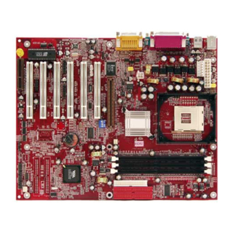
Chapter 1 Specification 1-2 Series SL-85DRV -- Layout with Optional Features Mouse PS/2 (on top) PS/2 K/B (underside) USB0 mPGA478B (on top) CN3 Aux ATX (underside) USB1 J4 ATX12V VT8753 P4X266 FAN3 AGP 4X LPC I/O Controller PCI 1 1 2 3 4... -
Page 14: Mainboard Specification Table
Series SL-85DRV 1-3 Mainboard Specification Table 85DRV 85DRV -X 85DRV 85DRV-X Series 85DRV Memory VIA VT8753 P4x266 North Bridge Controller Hub VIA VT8233 South Bridge Controller Hub CPU Socket Socket PGA478B for Intel Pentium 4 478-pin package CPU Supporting Registered/3GB or unbuffered/1.5GB... -
Page 15: Chipset System Block Diagram
Chapter 1 Specification 1-4 Chipset System Block Diagram (with respect to Series SL-85DRV) Intel Pentium 4 478-pin package 400MHz (100MHz QDR) FSB VT8753 PC2100/1600 DDR Memory Bus P4x266 AGP 2X/4X Bus Slot Single-chip SDRAMs North Bridge 664-pin PBGA 66MHz QDR, 8Bit V-Link... - Page 16 Series SL-85DRV MEMO MEMO...
-
Page 17: Chapter 2 Hardware Setup
Chapter 2 Hardware Setup Chapter Hardware Setup To Get things ready for Hardware setup ! 1. We recommend to install your CPU before any other components. For detailed installation instructions of processor, you can also refer to the pamphlet enclosed in your CPU package. 2. -
Page 18: Cpu Pentium 4 Installation With Socket 478
Series SL-85DRV 2-1 CPU Pentium 4 Installation with Socket 478 This series of mainboards is built with CPU Socket 478 (with 478 pins) supporting the Intel Pentium 4 CPU: • Follow the steps described in this section to install the 478-pin Pentium 4 CPU into the on board Socket 478. -
Page 19: Pentium 4 Cpu Fan Installation
Chapter 2 Hardware Setup 2-2 Pentium 4 CPU Fan Installation: Pentium 4 Fanbase CPU Fan Connector Connect to CPU FAN connector Press down 4 latches to lock fan to fanbase... -
Page 20: Memory Installation
Series SL-85DRV 2-3 Memory Installation How to tackle with the memory Modules: • Make sure to unplug your power supply before adding or removing memory module. Failure to do so may cause severe damage to both your main board and the memory module. -
Page 21: 2-3.2 To Remove A Dimm
Chapter 2 Hardware Setup 2-3.2 To Remove a DIMM: Press down the holding latches on both sides of socket and the module will be released from the DIMM socket. 2-3.3 Indicator ZD1 DIMM Socket On: An indicator ZD1 is designed on board. Whenever system is started or is in STR status (Suspend to RAM), all the DIMM sockets on board will also get powered on with the set voltage, resulting in ZD1 lighting up. -
Page 22: Agp 4X (Accelerated Graphics Port) Card Installation
Series SL-85DRV 2-4 AGP 4X (Accelerated Graphics Port) Card Installation : The AGP 4X slot on board supports 4X / 2X AGP card configuration. User can install either a 4X or 2X AGP card. AGP Accelerator AGP 4X / 2X... -
Page 23: Hdd/Fdd Installation
Chapter 2 Hardware Setup 2-5 HDD/FDD Installation To install HDD (Hard Disk Drive), you may connect the connector of IDE cable to the primary (IDE1) or secondary (IDE2) connector on board, and then connect the gray connector to your slave device and the black connector to your master device. - Page 24 Series SL-85DRV To install FDD (Floppy Disk Drive), you should connect the end of cable with single connector to the board , and connect the other end with two plugs to the floppy drives. PS/2 Mouse (on top) PS/2 K/B...
-
Page 25: Atx V 2.03 Power Supply Installation
Chapter 2 Hardware Setup 2-6 ATX V 2.03 Power Supply Installation PS/2 Mouse (on top) PS/2 K/B (underside) USB0 mPGA478B (on top) CN3 Aux ATX (underside) USB1 Main ATX Power (20-pin) Aux ATX J4 ATX12V Connector VT8753 (6-pin) P4X266 FAN3 AGP 4X ATX+12V LPC I/O... -
Page 26: Jumper And Switch Settings
Series SL-85DRV 2-7 Jumper and Switch Settings The following diagrams show the locations and settings of jumper blocks on the mainboard. JBAT1 CPU Clock Select 1234 (Default) Off On On On closed CPU clock (MHz) To clear CMOS (default) 1-2 closed... -
Page 27: 2-7.1 Switch 1 Cpu Clock Select
Chapter 2 Hardware Setup How to tackle with Jumpers: • Do not remove the jumper when power is on. Always make sure the power is off before changing any jumper settings. Otherwise, mainboard could be damaged. • In the Jumper setting diagram, all jumper pins covered with black marks stand for closed pins by jumper caps. -
Page 28: 2-7.2 Jbat1 Clear Cmos
2-7.3 Jp12 RAID Controller Select: On board SL-85DRV and SL-85DRV -X only. F o r t h e m a i n b o a r d s c a r r y i n g P r o m i s e R A I D... -
Page 29: 2-7.4 Jp18 Voice Diagnostic Language Select
Chapter 2 Hardware Setup 2-7.4 Jp18 Voice Diagnostic Language Select On board SL-85DRV-X, and 85DRV • A Voice Diagnostic Function is incorporated in “Advanced BIOS Features” of the “Award BIOS Setup” as “VD-Tech II Function”. With this function enabled in “Advanced BIOS Features”, it will voice out the problems or conflicts whenever user configures the components or boots up the PC system. -
Page 30: 2-7.5 Jp16 Suspend To Ram (Str)
Series SL-85DRV 2-7.5 Jp16 Suspend to RAM (STR) Jp16 is designed to support the S3 mode (Suspend to RAM) of ACPI (Advanced Configuration and Power interface) which is usually inte- grated in such operating systems as Win 98se or Win 2000. -
Page 31: Other Connectors Configuration
Chapter 2 Hardware Setup 2-8 Other Connectors Configuration This section lists out all connectors configurations for users’ reference. 2-8.1 On Board FAN Connectors (FAN1,FAN2, FAN3) PS/2 Mouse (on top) PS/2 K/B (underside) USB0 +12V mPGA478B (on top) CN3 Aux ATX USB1 (underside) SENSOR... -
Page 32: 2-8.2 Wol1 Wake On Lan
Series SL-85DRV 2-8.2 WOL1 Wake On LAN PS/2 Mouse (on top) PS/2 K/B (underside) USB0 mPGA478B (on top) CN3 Aux ATX USB1 (underside) Standby J4 ATX12V VT8753 P4X266 FAN3 AGP 4X Wake On LAN: LPC I/O Controller PCI 1 1 2 3 4... -
Page 33: 2-8.3 Cd-Rom Audio Connector (Cd_In1/Cd_In2)
Chapter 2 Hardware Setup 2-8.3 CD-ROM Audio Connector (CD_IN1/CD_IN2) PS/2 Mouse (on top) PS/2 K/B (underside) USB0 mPGA478B (on top) CN3 Aux ATX (underside) USB1 CD_IN1 CD-ROM Audio Pin Assignment J4 ATX12V VT8753 P4X266 PIN NO. CD_IN1 FAN3 AGP 4X Left LPC I/O Controller... -
Page 34: 2-8.5 Thermal Sensor Connector (Rt2)
Series SL-85DRV 2-8.5 Thermal Sensor Connector (RT2) PS/2 Mouse (on top) PS/2 K/B Thermal Sensor Connector (underside) USB0 mPGA478B (on top) (RT2): CN3 Aux ATX USB1 (underside) RT2: THERMAL SENSOR CONNECTOR a: Connect to RT2. b: Connect this thermal sensor... -
Page 35: 2-8.6 Complex Header Njp1
Chapter 2 Hardware Setup 2-8.6 Complex Header NJP1 This complex Header consists of 9 connectors providing various supports: Promise RAID NJP1 SUSPEND LED SMI SIGNAL SUSPEND LED SIGNAL POWER SWITCH ATX POWER SWITCH POWER LED NO CONNECTION NO CONNECTION INFRARED TRANSMIT SIGNAL INFRARED(IR) INFRARED TRANSMIT SIGNAL RESET SWITCH... - Page 36 Series SL-85DRV 1. SMI Connector (System Management Interrupt): CONNECTION: This 2-pin connector is connected to the case-mounted Suspend Switch. FUNCTION: Manually placing the system into a Suspend mode or “Green” mode. 2. Power Switch Connector: CONNECTION: Connected to a momentary button or switch.
-
Page 37: 2-8.7 Atx Power Supply Connectors For Pentium 4
Chapter 2 Hardware Setup 2-8.7 ATX Power Supply Connectors for Pentium 4 • ATX 2.03 Power supply connectors consists of 3 main connectors: (1) Main ATX Power Connector; (2) Aux Power Connector: a 6-pin connector supporting +3.3V and +5V; (3) +12V Power Connector: a 4-pin connector supporting +12V; •... -
Page 38: 2-8.8 Communication And Networking Riser Slot (Cnr)
Series SL-85DRV 2-8.8 Communication And Networking Riser Slot (CNR) This slot on this series of mainboards allows you to use modem or audio riser card only. Mouse PS/2 (on top) PS/2 K/B (underside) USB0 mPGA478B (on top) CN3 Aux ATX... -
Page 39: 2-8.9 Usb Ports And Usb Headers (Header Usb 2 & 3)
Chapter 2 Hardware Setup 2-8.9 USB Ports and USB Headers (Header USB 2 & 3) This series of mainboards provides two USB ports USB0 and USB1 on board supporting various USB devices. In addition, 2 USB headers are added on board to provide four additional USB ports by using two additional USB Cables. -
Page 40: Irq Description
Series SL-85DRV 2-9 IRQ Description Function Description Priority IRQ 0 System Timer IRQ 1 Keyboard Controller IRQ 2 Programmable Interrupt IRQ 3 Serial Port (COM 2) IRQ 4 Serial Port (COM 1) IRQ 5 Free IRQ 6 Floppy Disk Controller... - Page 41 Chapter 2 Hardware Setup MEMO MEMO...
-
Page 42: Chapter 3 Software Setup
3-1 Open Support CD and choose your drivers 3-2 4-in-1 Drivers Installation 3-3 AC’97 Audio CODEC Drivers Installation 3-4 Hardware Monitor Utility Installation 3-5 Promise RAID Drivers Installation ( for SL-85DRV and SL-85DRV -X only ) -
Page 43: Open Up The Suport Cd And Choose Drivers And Utilities
Chapter 3 Software Setup 3-1 Open up the Suport CD and choose Drivers and Utilities: (1) Please put the Support CD enclosed in your mainboard package into the CD-ROM drive. In a few seconds, the Main Menu will automatic- ally appear, displaying the contents to be installed for this series: Install VIA 4in1 Driver Install VIA AC’97 Audio Driver Install Hardware Monitor Utility... -
Page 44: Proceed To Via 4-In-1 Drivers Installation
Series SL-85DRV 3-2 Proceed to VIA 4-IN-1 Drivers Installation Following the procedures of opening the Support CD, click to “ VIA 4in1 Drivers” to proceed. “VIA Service Pack README” The VIA Service Pack InstallShield screen will appear, please click Wizard will pop up to guide you to the “Yes”... - Page 45 Chapter 3 Software Setup Click on “Click to enable DMA Select “Install VIA ATAPI Mode” checkbox to enable DMA Vendor Support Driver” function, then click the “Next” checkbox, then click the “Next” button to continue. button to continue. Next Next Select “Install VIA IRQ Routing Select “Install VIA AGP VxD”...
-
Page 46: Proceed To Ac'97 Audio Driver Installation
Series SL-85DRV 3-3 Proceed to AC’97 AUDIO DRIVER Installation Following the installation of VIA 4in1 drivers, you have to restart system so that your system can be reconfigured with VIA 4in1. When restarting procedures finish, please open the Support CD with your CD-ROM to enter the Main Installation Menu. -
Page 47: Proceed To Hardware Monitor Installation
Chapter 3 Software Setup 3-4 Proceed to HARDWARE MONITOR Installation Following the installation of AC’97 driver, you have to install Hardware Monitor manually. Please click to the following path to execute Hardware Monitor installation: D: \ Hardwaremonitor\ ITE2 \ Install.exe (assuming that your CD-ROM Drive is Drive D) In case you are already on the Installation Main Menu of the Support CD, please click to the “Install Hardware Monitor”. - Page 48 Series SL-85DRV In a few seconds, installation of Hardware Monitor is complete. Please click on the “OK” Dialog Box to finish installation. To display the Hardware Monitor Utility, just click on the “ITE SMARTGUARDIAM” icon in your program file, and the following screen of Smartguardian Control Panel will show up, displaying the information about system temperatures, voltages and Fan speed.
-
Page 49: Install Driver For Promise Raid Controller
Chapter 3 Software Setup 3-5 Install Driver for Promise RAID Controller Promise RAID Controller is built on SL-85DRV and SL-85DRV Before installing the driver for Promise RAID Controller, please check the following points: (1) Set up Jumper Jp12 on board to enable Promise RAID Controller. - Page 50 Series SL-85DRV MEMO MEMO...
-
Page 51: Chapter 4 Bios Setup
Chapter 4 BIOS Setup Chapter BIOS Setup THE BIOS • BIOS stands for Basic Input and Output System. It was once called ROM BIOS when it was stored in a Read-Only Memory(ROM) chip Now manufacturers would like to store BIOS in EEPROM which means Electrically Erasable Programmable Memory. -
Page 52: About Bios Setup
Series SL-85DRV 4-1 About BIOS Setup • BIOS setup is an interactive BIOS program that you need to run when: 1. Changing the hardware of your system. (For example: installing a new Hard Disk etc.) 2. Modifying the behavior of your computer. (For example: changing the system time or date, or turning special features on or off etc.) -
Page 53: To Upgrade Bios
Chapter 4 BIOS Setup 4-5 To upgrade BIOS • System BIOS is incorporated into a Flash memory component. Flash BIOS allows user to upgrade BIOS without the need to replace an EPROM component. • The Upgrade Utility can be loaded on a floppy diskette to execute saving, verifying, and updating the system BIOS. - Page 54 Series SL-85DRV Step 4. Type awdflash *.bin /sn/py/cc and then press <Enter> to run BIOS upgrade program. (*.bin depends on your mainboard model and version code. Instead of typing “*”, you should type specific file name for your specific mainboard).
- Page 55 Chapter 4 BIOS Setup Award Flash Memory Writer Start Screen Award Flash Memory Writer Complete Screen...
- Page 56 Series SL-85DRV The parameters of AWDFLASH.EXE /sn: No original BIOS backup /py: Program flash memory /cc: Clear CMOS data (and update data automatically) after pro- gramming NOTE: Users can type AWDFLASH /? to get further details about the parameters. Incorrect usage of the parameter will damage the BIOS information, so we strongly recommend user to leave parameters alone unless you fully understand their function.
-
Page 57: Bios Setup
Chapter 4 BIOS Setup 4-6 BIOS SETUP --- CMOS Setup Utility 4-6.1 CMOS Setup Utility • This Series of mainboards comes with the AWARD BIOS from AWARD Software Inc. Enter the CMOS Setup Utility Main Menu by: 1. Turn on or reboot your system. After a series of diagnostic checks, the following message will appear: PRESS <DEL>... -
Page 58: 4-6.2 Standard Cmos Setup
Series SL-85DRV 4-6.2 Standard CMOS Setup • Standard CMOS Setup records some basic system hardware configuration and sets the system clock and error handling. You only need to modify the configuration values of this option if you want to change your system hard- ware configuration or when the data stored in the CMOS memory gets lost or damaged. - Page 59 Chapter 4 BIOS Setup Date (mm:dd:yy) The BIOS determines the day of the week from the other date information. This field is for information only. Press the left or right arrow key to move to the desired field (date, month, year). Press the PgUp or PgDn key to increment the setting, or type the desired value into the field.
- Page 60 Series SL-85DRV Drive A / Drive B Select this field to the type(s) of floppy disk drive(s) installed in your system. The choices are: 360KB, 5.25in; 1.2MB, 5.25in; 720KB, 3.5in; 1.44MB, 3.5in; 2.88MB, 3.5in; None. Video Select the type of primary video subsystem in your computer.
-
Page 61: 4-6.3 Advanced Bios Features
Chapter 4 BIOS Setup 4-6.3 Advanced BIOS Features • ADVANCED BIOS FEATURES improves your system performance or sets up system features according to your preference. Run the ADVANCED BIOS FEATURES as follows: 1. Choose “ADVANCED BIOS FEATURES” from the Main Menu and a screen with a list of options will appear: CMOS Setup Utility - Copyright (C) 1984 - 2001 Award Software Advanced BIOS Features... - Page 62 Series SL-85DRV 2. Use one of the arrow keys to move between options and modify the selected options by using PgUp / PgDn / + / - keys. An explanation of the <F> keys follows: <F1>: “Help” gives options available for each item.
- Page 63 Chapter 4 BIOS Setup CPU L2 Cache ECC When you select Enabled, it will speed up memory Checking checking when the external cache contains ECC SRAMs. The choices: Enabled; Disabled. Quick Power On Self Select Enabled to reduce the amount of time required to Test run the power-on self-test (POST).
- Page 64 Series SL-85DRV Typematic Rate Setting When Disabled, the following two items (Typematic Rate and Typematic Delay) are irrelevant. Keystroke repeats at a rate determined by the keyboard controller in your system. When Enabled, you can select a typematic rate and typematic delay.
-
Page 65: 4-6.4 Advanced Chipset Features
Chapter 4 BIOS Setup 4-6.4 Advanced Chipset Features • ADVANCED CHIPSET FEATURES is used to modify the values of chipset buffers. These buffers control the system options. Run the ADVANCED CHIPSET FEATURES as follows: 1. Choose “ADVANCED CHIPSET FEATURES” from the Main Menu and a list of option will appear: CMOS Setup Utility - Copyright (C) 1984-2001 Award Software Advanced Chipset Features... - Page 66 Series SL-85DRV DRAM CLOCK/DRIVE CONTROL • When this option is chosen, the following item appears for user’s configuration. CMOS Setup Utility - Copyright (C) 1984-2001 Award Software DRAM Clock/Drive Control Item Help Current FSB Frequency Menu Level Current DRAM Frequency...
- Page 67 Chapter 4 BIOS Setup AGP & P2P BRIDGE CONTROL • When this option is chosen, the following item appears for user’s configuration. CMOS Setup Utility - Copyright (C) 1984-2001 Award Software AGP & P2P Bridge Control Item Help AGP Aperture Size Menu Level AGP Mode Auto...
- Page 68 Series SL-85DRV * AGP Fast Write This item will enable the AGP model into fast write mode. If your graphics card does not support this function, please do not enable this function. * AGP Master 1 ws Leave this field at default.
- Page 69 Chapter 4 BIOS Setup * PCI Master 0 WS When Enabled, writes to the PCI bus are executed Write with zero wait states. The choices: Enabled, Disabled * PCI Delay Transac- Leave this field at default tion Memory Hole In order to improve performance, certain space in memory is reserved for ISA cards.
-
Page 70: 4-6.5 Integrated Peripherals
Series SL-85DRV 4-6.5 Integrated Peripherals • INTEGRATED PERIPHERALS option allows you to get some informa- tion inside your system when it is working. Run the INTEGRATED PERIPHERALS as follows: 1. Choose “INTEGRATED PERIPHERALS” from the Main Menu and a list... -
Page 71: Via Onchip Ide Device
Chapter 4 BIOS Setup VIA ONCHIP IDE DEVICE • When this option is chosen, the following item appears for user’s configuration. CMOS Setup Utility - Copyright (C) 1984-2001 Award Software VIA OnChip IDE Device Item Help OnChip IDE Channel0 Enabled OnChip IDE Channel1 Menu Level Enabled... -
Page 72: Via Onchip Pci Device
Series SL-85DRV * Primary Choose Auto or Mode 0~4. The BIOS will detect the Master / Slave PIO HDD mode type automatically when you choose Secondary Auto. You need to set to a lower mode than Auto Master / Slave PIO when your hard disk becomes unstable. - Page 73 Chapter 4 BIOS Setup VIA SUPER IO DEVICE • When this option is chosen, the following item appears for user’s configuration. CMOS Setup Utility - Copyright (C) 1984-2001 Award Software VIA SuperIO Device Item Help Onboard FDC Controller Enabled Onboard Serial Port 1 Auto Menu Level Onboard Serial Port 2...
- Page 74 Series SL-85DRV * UART Mode Select The second serial port on your system may offer a variety of infrared port modes. Click here for a description of various modes. (Click your browser ’s Back button, or your right mouse button, to return to this page.) The choices: Standard;...
- Page 75 Chapter 4 BIOS Setup Init Display First Initialize the AGP video display before initializing any other display device on the system. Thus the AGP display becomes the primary display. OnChip USB Control- Select Enabled if your system contains a Universal Serial Bus (USB) controller and you have USB peripherals.
-
Page 76: 4-6.6 Power Management Setup
Series SL-85DRV 4-6.6 Power Management Setup • POWER MANAGEMENT SETUP allows you to set the system’s power saving functions. Run the POWER MANAGEMENT SETUP as follows: 1. Choose “POWER MANAGEMENT SETUP” from the Main Menu and a list of options will appear:... - Page 77 Chapter 4 BIOS Setup ACPI Function Select Enabled only if your computer’s operating system supports the Advanced Configuration and Power Interface (ACPI) specification. Currently, Windows NT 5.0 supports ACPI. ACPI Suspend Type This item allows you to select the ACPI suspend type.
- Page 78 Series SL-85DRV Always On Monitor will remain on during power saving modes. Monitor blanked when the systems enters the Suspend Suspend --> Off mode. Monitor blanked when the system enters either Suspend or All Modes --> Off Standby modes. Video Off Method This determines the manner by which the monitor is blanked.
- Page 79 Chapter 4 BIOS Setup IRQ/EVENT ACTIVITY DETECT • When this option is chosen, the following item appears for user’s configuration. CMOS Setup Utility - Copyright (C) 1984-2001 Award Software IRQ/Event Activity Detect Item Help LPT/COM LPT & COM Menu Level HDD &...
- Page 80 Series SL-85DRV * PowerOn by PCI Card This item allows system wake up by PCI Device. * Modem Ring Resume An input signal on the serial Ring Indicator (RI) Line (in other words, an incoming call on the modem) Awakens the system from a soft off state.
- Page 81 Chapter 4 BIOS Setup * IRQ ACTIVITY MONITORING • When this option is chosen, the following item appears for user’s configuration. CMOS Setup Utility - Copyright (C) 1984-2001 Award Software IRQ Activity Monitoring Primary INTR Item Help IRQ-3 (COM2) Enabled Menu Level IRQ-4 (COM1) Enabled...
-
Page 82: 4-6.7 Pnp / Pci Configuration
Series SL-85DRV 4-6.7 PNP / PCI Configuration • PNP/PCI CONFIGURATION allows you to modify the system’s power saving functions. Run the PNP/PCI Configuration as follows: 1. Choose “PNP/PCI CONFIGURATION” from the Main Menu and a screen with a list of options will appear:... - Page 83 Chapter 4 BIOS Setup PNP OS Installed Select Yes if the system operating environment is Plug-and-Play aware (e.g., Windows95). NOTE: BIOS will automatically disable all PnP resources except the boot device card when you select Yes on Non-PnP operating system. Reset Configuration Normally, you leave this Disabled.
- Page 84 Series SL-85DRV PCI/VGA Palette Snoop This option allows the BIOS to preview VGA status, and to modify the information delivered from the feature Connector of the VGA card to MPEG card. This option can solve the display inversion to black after you have used MPEG card.
-
Page 85: 4-6.8 Smartdoc Anti-Burn Shield (Pc Health Status)
Chapter 4 BIOS Setup 4-6.8 SmartDoc Anti-burn Shield (PC Health status) • This section helps you to get more information about your system including CPU temperature, FAN speed and voltage. It is recommended that you contact your mainboard supplier to get proper values about the setting of the CPU temperature. - Page 86 Series SL-85DRV Shutdown Tempera- This feature prevents your CPU from damage by ture over heat. If the CPU’s temperature is higher than “CPU warning temperature” that you select in this field, the BIOS will shut down your system within 3 seconds.
-
Page 87: 4-6.9 Frequency/Voltage Control
Chapter 4 BIOS Setup 4-6.9 Frequency/Voltage Control Run the “FREQUENCY/VOLTAGE CONTROL” as following: 1. Choose “FREQUENCY/VOLTAGE CONTROL” from the Main Menu and a screen with a list of options will appear: CMOS Setup Utility - Copyright (C) 1984-2001 Award Software Frequency / Voltage Control Item Help CPU Vcore Select... - Page 88 Series SL-85DRV CPU Vcore This item allows you to adjust the CPU core Voltage. Select Using higher CPU core Voltage may help CPU overclocking but may shorten the life of your processor. It is strongly recommended that you leave this item at default.
-
Page 89: 4-6.10 Load Optimized Defaults
Chapter 4 BIOS Setup 4-6.10 Load Optimized Defaults • When you press <Enter> on this item, you will get a confirmation dialog box with a message similar to: “ Load Optimized Defaults (Y / N) ? N ” CMOS Setup Utility - Copyright (C) 1984 - 2001 Award Software Frequency/Voltage Control Standard CMOS Features Load Optimized Defaults... -
Page 90: 4-6.12 Set Supervisor / User Password
Series SL-85DRV 4-6.12 SET SUPERVISOR / USER PASSWORD • These two options allow you to set your system passwords. Normally, the supervisor has a higher priority to change the CMOS setup option than the users. The way to set up the passwords for both Supervisor and Users are as follows: 1. -
Page 91: 4-6.13 Save & Exit Setup
Chapter 4 BIOS Setup 4-6.13 SAVE & EXIT SETUP • SAVE & EXIT SETUP allows you to save all modifications you have speci- fied into the CMOS memory. Highlight this option on the Main Menu and the following message appears: “SAVE to CMOS and EXIT (Y/N) ? Y “... - Page 92 Series SL-85DRV MEMO MEMO...
-
Page 93: Chapter 5 Raid Controller
Chapter 5 RAID Controller Chapter RAID Controller The following topics and Appendices are included in this chapter: 5-0 Before Creating Disk Array 5-1 Creating your Disk Array 5-2 Using FASTBUILD Configuration Utility 5-3 Installing FAST TRAK100-LITE Driver... -
Page 94: Before Creating Disk Array
Series SL-85DRV 5-0 Before Creating Disk Array: (1) Please locate the Promise RAID Controller on your mainboard to make sure that you are using the right board. (2) Locate the RAID Controller Select Jumper JP12 on board, and make sure this Jumper is set at Pin 1-2 closed for enabling IDE RAID controller. -
Page 95: Creating Your Disk Array
Chapter 5 RAID Controller 5-1 Creating Your Disk Array To create your disk array, you have to open the FastBuild Utility, which should have already been built in your system BIOS through the Promise Controller. You can create two types of array with the help of FastBuild Utility. - Page 96 Series SL-85DRV 3. Press “1” to display the Auto Setup Menu below. This is the fastest and easiest method to create your first array. FastBuild (tm) Utility 1.xx (c) 1995-2000 Promise Technology, Inc. [Auto Setup Options Menu] Optimize Array for:...
-
Page 97: 5-1.2 Creating A Security (Mirror) Array With New Drives
Chapter 5 RAID Controller 5-1.2 Creating A Security (Mirror) Array With New Drives FastTrak100-Lite on board permits only two drives to be used for a single Mirroring array with FastBuild Utility. 1. Boot your system with FastTrak100-Lite Controller enabled by JP12 and your hard drive(s) connected to IDE3/IDE4. - Page 98 Series SL-85DRV 4. Using the Spacebar, choose “Security” under the “Optimize Array for ” section. 5. Press <Ctrl-Y> keys to save and create the array. 6. The window below will appear: Do you want the disk image to be duplicated to anther? (Yes/No)
-
Page 99: 5-1.3 Creating Security Array With Existing Data Drive
Chapter 5 RAID Controller 5-1.3 Creating Security Array With Existing Data Drive FastTrak100-Lite on board permits only two drives to be used for a single Mirroring (Security) array with FastBuild Utility. Checkpoints before creating a Security Array: (1) You may use a drive that is containing data or a bootable O/S. Then you will need another new drive of identical or larger storage capacity. - Page 100 Series SL-85DRV 3. Press “1” to display the Auto Setup Menu below. This is the fastest and easiest method to create your first array. FastBuild (tm) Utility 1.xx (c) 1995-2000 Promise Technology, Inc. [Auto Setup Options Menu] Optimize Array for:...
- Page 101 Chapter 5 RAID Controller 6. Press “Y” for the “Create and Duplicate” option. The window below will appear asking you to select the Source drive to use. Source Disk Channel: ID Drive Model Capacity (MB) Target Disk Channel: ID Drive Model Capacity(MB) [Please Select A Source Disk] Channel: ID...
-
Page 102: Using Fastbuildtm Configuration Utility
Series SL-85DRV 5-2 Using FASTBUILD Configuration Utility The FastBuild Configuration Utility offers several menu choices to create and configure the drive array on the Promise FastTrak100-Lite. In this Section, it is assumed you have already created an array in the previous Section and now wish to make a change to the array or view other status . -
Page 103: 5-2.2 Navigating The Fastbuildtm Setup Menu
Chapter 5 RAID Controller 5-2.2 Navigating the FastBuild Setup Menu When using the menus, there are some of the basic navigation tips: Arrow keys highlights through choices; [ESC] key is used to abort or exit the current menu. 5-2.3 Using the Main Menu This is the first option screen when entering the FastBuild Setup. -
Page 104: 5-2.4 Creating Arrays Automatically
Series SL-85DRV 5-2.4 Creating Arrays Automatically The Auto Setup <1> selection from the Main Menu can intuitively help create your disk array. It will assign all available drives appropriate for the disk array you are creating. After making all selections, use Ctrl-Y to save selections. - Page 105 Chapter 5 RAID Controller 5-2.4-1 Optimize Array For Select whether you want Performance (RAID 0), or Security (RAID 1) under the “Optimize Array for” setting. (1) Performance (RAID 0 Striping) Supports the maximum performance. The storage capacity equals the number of drives times the capacity of the smallest drive in the disk array. NOTE: FastT rak100-Lite permits striped arrays of 1 or 2 drives attached in Auto Setup mode.
-
Page 106: 5-2.5 Viewing Drive Assignments
Series SL-85DRV 5-2.5 Viewing Drive Assignments The View Drive Assignments <2> option in the Main Menu displays whether drives are assigned to a disk array or are unassigned. Under the “Assignment” column, drives are labeled with their assigned disk array or shown as “Free” if unassigned. Such “Free” drives can be used for a future array or used as a spare drive when a drive fails in a mirrored array. -
Page 107: 5-2.7 Adding Fault Tolerance To An Existing Drive
Chapter 5 RAID Controller 5-2.7 Adding Fault Tolerance to an Existing Drive FastTrak100-Lite will create a mirroring array using an existing system drive with data. You must assign the existing drive and another drive of same or larger capacity to the Mirroring array. The BIOS will send the existing data to the new blank drive. -
Page 108: 5-2.8 Making A Fasttrak100-Lite Disk Array Bootable
Series SL-85DRV 3. Use the arrow keys to choose which drive containing the existing data to be copied. WARNING : WARNING : All target drive data will be erased. Make sure you choose the correct drive. 4. Press <Ctrl-Y> keys to save selection and start duplication. The following confirmation screen will appear. -
Page 109: 5-2.9 Creating A "Hot" Spare Drive For Mirroring Arrays
Chapter 5 RAID Controller 1. Once you have returned to the Define Array Menu window (below), you will see the array(s) you have created. You now may use the menu to select which previously-defined array will be used as the bootable array. FastBuild (tm) Utility 1.xx (c) 1995-2000 Promise Technology, Inc. -
Page 110: 5-2.10 How Fasttrak100-Lite Orders Arrays
Series SL-85DRV 5-2.10 How FastTrak100-Lite Orders Arrays During startup, the disk arrays on the FastTrak100-Lite are recognized in this order: 1) The array set to bootable in the FastBuild Setup, and 2) the Array number (i.e. Array 0, Array 1 ...). This would involve determining which drive letters will be assigned to each disk array. - Page 111 Chapter 5 RAID Controller FastBuild (tm) Utility 1.xx (c) 1995-2000 Promise Technology, Inc. [ Delete Array Menu ] Array No RAID Mode Total Drv Capacity(MB) Status Array 1 Stripe 16126 Functional Array 2 -------- ---------- --------------- --------- Array 3 -------- ---------- --------------- ---------...
-
Page 112: 5-2.13 Rebuilding A Mirroring Array
Series SL-85DRV 5-2.13 Rebuilding A Mirroring Array The Rebuild Array <5> Menu option is necessary for recovering from an error in a mirrored disk array. You will receive an error message when booting your system from the FastTrak BIOS. NOTE: Drives MUST be replaced if they contain any physical errors. - Page 113 Chapter 5 RAID Controller FastBuild (tm) Utility 1.xx (c) 1995-2000 Promise Technology, Ine. [ Delete Array Menu ] Array No RAID Mode Total Drv Status Array 2 Mirror Critical Stripe Block: Not Available [ Select Drive for Rebuild ] Channel : ID Drive Model Capacity (MB) Assignment 1 : Slave...
-
Page 114: 5-2.14 Viewing Controller Settings
Series SL-85DRV 5-2.14 Viewing Controller Settings The Controller Configuration <6> menu selection allows you to enable or disable the halting function of FastTrak100-Lite BIOS (the default) if it detects an error on boot up. You may also view the system resources (Interrupt and I/O port address) of FastTrak’s data channels. -
Page 115: Installing Drivers
Chapter 5 RAID Controller 5-3 Installing Drivers This section details the FastTrak100-Lite driver installation for various op- erating systems. The driver should have been included either into the Sup- port CD or into a Support Floppy Diskette. Checkpoints for the driver installation: (1) To install FastTrak100-Lite Driver for an operating system, you must use the driver in Floppy Diskette instead of the one in CD. - Page 116 Series SL-85DRV 6. The Windows 2000 Setup screen will appear again saying “Setup will load support for the following mass storage devices:” The list will include “Win2000 Promise FastTrak100-Lite controller”. Note: If you need to specify any additional devices to be installed, do so at this time.
-
Page 117: 5-3.2 Windows 95/98
Chapter 5 RAID Controller 7. Power off your system, then attach your hard drive to the FastTrak100- Lite controller card, e.g. IDE3/IDE4. 5-3.1-3 Confirming Windows 2000 Installation 1. From Windows 2000, open the Control Panel from “ My Computer” followed by the System icon. 2. - Page 118 Series SL-85DRV 10. Choose “Specify Location,” and then type “A:\WIN95-98” in the text box. 11. Insert the “FastTrak100-Lite Driver” diskette into the A: drive. 12. Press the “Next” button. A message informing you that Windows 98 has found “Win95-98 Promise FastTrak100-Lite (tm) Controller” should appear.
- Page 119 Chapter 5 RAID Controller 5-3.2-4 Installing Drivers With Existing Windows 95/98 The following three sections detail the installation of the FastTrak100-Lite drivers on a system that has Windows 95/98 already installed. If you’re installing the FastTrak100-Lite drivers on a system during a Windows 95/ 98 installation, see “Installing Drivers During Windows 95/98 Installation”.
-
Page 120: 5-3.3 Dos/Windows 3.1X
Series SL-85DRV 6. If a message informing you that the file “Win95/98 Promise FastTrak100- Lite.MPD” cannot be found, go to the “Copy files from:” text box and type: “A:\WIN9x-ME”. 7. Choose “Yes” when asked whether you want to start your computer. Be sure to remove the diskette from drive A. -
Page 121: 5-3.4 Windows Nt4.0
Chapter 5 RAID Controller 5-3.4 Windows NT4.0 5-3.4-1 Installing Drivers During Windows NT 4.0 Installation 1. Connect your hard drive(s) for RAID Array to IDE3/IDE4, and enable FastTrak100-Lite Controller with JP12. Start the system installation by booting from the Windows NT disk: a) Floppy install: boot the system with the Windows NT installation diskettes. - Page 122 Series SL-85DRV 5-3.4-2 Installing Drivers With Existing Windows NT4.0 W A R N I N G : W A R N I N G : Your must first complete installing the driver before moving the boot drive containing the existing Windows 2000 operating system on to the FastTrak100-Lite controller (e.g.
- Page 123 Chapter 5 RAID Controller MEMO MEMO...
-
Page 124: Appendices
Series SL-85DRV APPENDICES APPENDICES APPENDICES APPENDICES APPENDICES Appendix-1 Identifying BIOS Version and BIOS Part Number Appendix-2 Identifying Mainboard Model Number Appendix-3 Technical Terms... -
Page 125: Appendix-1 Identify Bios Version & Bios Part Number
APPENDIX Appendix-1 Identify BIOS Version & BIOS Part Number • When you boot up your computer, the first screen popping up will show you the BIOS version and BIOS part number identification as below: Picture 1 BIOS Version example: REV T2.1 BIOS ID String example: 6A69RSNCC... -
Page 126: Appendix-2 Identify Mainboard Model Number
Series SL-85DRV Appendix-2 Identify Mainboard Model Number • Usually the mainboard model number is labeled on the side of ISA side of slot or PCI slot. Please see Picture 2 below as an illustration: Picture 2 (The mainboard in this picture is taken as an example only, and... -
Page 127: Appendix-3 Technical Terms
APPENDIX Appendix-3 Technical Terms AC’97 AC’97 is a device designed to include a digital processor for modem and an audio CODEC for analog I/O. These two parts are linked together by AC’97 link bus. Putting the digital processor into the main system chipset will reduce the cost of sound/modem onboard solution. - Page 128 Series SL-85DRV ATAPI (AT Attachment Packet Interface) This is the exension of the EIDE (extended IDE) that enables the interface to support CD-ROM players and tape drives. BIOS (Basic Input/Output System) BIOS is a set of assembly routine/program that resides in EPROM or Flash ROM.
- Page 129 APPENDIX DMA (Direct Memory Access) Channel for communications between memory and surrounding devices. ECC (Error Checking and Correction) The ECC algorithm has the ability to detect double-bit error and automatically correct single-bit error while parity mode can only detect single-bit error. ECP (Enhanced Communication Port) ECP is a technology designed to improved I/O for parallel ports.
- Page 130 Series SL-85DRV FSB (Front Side Bus) FSB is the data channel connecting the Processor to chipset, RAM, mainboard buses, AGP socket etc. Its speed is in terms of MHz and is talked to as FSB clock: FSB Clock means CPU external bus clock.
- Page 131 APPENDIX conflicts. PnP BIOS or operating system will automatically allocate the IRQ/DMA/Memory. Currently, almost all the PCI cards and most ISA cards are already PnP compliant. POST (Power-On Self Test) The BIOS self-test procedure after power-on. It is generally the first or the second program shown on your monitor screen during system boot.
- Page 132 Series SL-85DRV SIMM (Single In Line Memory Module) SIMM socket is only 72-pin, and is only single side. The golden finger signals on each side of PCB are identical. That is why it is called Single In Line. SIMM is made of FPM or EDO DRAM and supports 32-bit data.
- Page 133 APPENDIX VCM (Virtual Channel Memory) NEC’s Virtual Channel Memory (VCM) is a new DRAM core architecture that dramatically improves the memory system’s ability to service multimedia requirements. VCM increases memory bus efficiency and performance of any DRAM technology by providing a set of fast static registers between the memory core and I/O pins.
- Page 134 Series SL-85DRV MEMO MEMO...
Need help?
Do you have a question about the SL-85DRV and is the answer not in the manual?
Questions and answers