
Related Manuals for SOLTEK SL-85DR-C


Summary of Contents for SOLTEK SL-85DR-C
- Page 1 T h e S o u l C o m p u t e r T e c h n o l o g y Mainboard SL-85DR-C User Manual V2.0...
- Page 2 Soltek Computer Inc. has been advised of the possibility of such damages arising from any defect or error in this manual or product.
- Page 3 SOLTEK AROUND THE WORLD SOLTEK COMPUTER INC. Address : 7F, No. 306-3, Ta-Tung Rd, Sec.1, Hsi-Chih, Taipei- Hsien, Taiwan, R.O.C. Telephone : 886-2-2642-9060 : 886-2-2642-9065 E-mail : sales@soltek.com.tw Web site : http://www.soltek.com.tw SOUL TECHNOLOGY EUROPE B.V. Address : Hongkongstraat 55, 3047 BP Rotterdam. The Neth-...
-
Page 4: Table Of Contents
85DR-C CONTENT Chapter 1 Specification ..........8 1-1 Mainboard Specifications ..........9 1-1.1 CPU Socket ................ 9 1-1.2 Sysem Chipset Architecture ..........9 1-1.3 Memory ................9 1-1.4 AMI BIOS V2.01A ............... 9 1-1.5 Hardware Monitoring ............9 1-1.6 Multi-I/O Function ............. 10 1-1.7 Expansion Slots .............. - Page 5 Content 2-6.4 JP13 Memory Stick/Secure Digital Memory Card Reader Select ................25 2-6.5 AGP Voltage Select (By JAGP1/JAGP2) ......25 2-6.6 JBAT1 Clear CMOS ............26 2-7 Other Connectors Configuration ........27 2-7.1 On Board FAN Connectors (FAN1,FAN2, FAN3) ....27 2-7.2 WOL1 Wake On LAN ............
- Page 6 85DR-C 4-2 To run BIOS Setup ............51 4-3 About CMOS ..............51 4-4 The POST ( Power On Self Test ) ........51 4-5 To upgrade BIOS ............52 4-5.1 Before Upgrading BIOS ............ 52 4-5.2 Upgrade Process .............. 52 4-6 BIOS Setup --- CMOS Setup Utility ........
- Page 7 Content ITEM LIST CHECKUP Mainboard Support CD Bundled Bonus Pack CD Bundled Bonus Pack Manual Temperature Sensor Cable (Optional) ATA66/100 IDE Cable RS232 Cable FDD Cable User’s Manual...
-
Page 8: Chapter 1 Specification
85DR-C Chapter Specification Introduction • This chapter introduces the characteristics of this series of mainboards. It includes the information on the chipset, CPU types, built-in functions and layout. Users will have more ideas about this powerful series after reading this chapter. The topics contained in this chapter are: 1-1 Mainboard Specifications 1-2 Mainboard Layout... -
Page 9: Mainboard Specifications
Chapter 1 Specification 1-1 Mainboard Specifications 1-1.1 CPU Socket • CPU Socket 478B on board, supporting Intel ® Pentium 4 and Northwood processors in the 478-pin package for 400MHz System Bus. 1-1.2 Sysem Chipset Architecture • INTEL 845-D Chipset Memory Control Hub (MCH): To work with Intel Pentium 4 Processor for managing and arbitrating between 4 interfaces: -- the System Bus (Host Interface);... -
Page 10: 1-1.6 Multi-I/O Function
85DR-C 1-1.6 Multi-I/O Function • Integrated IDE Controller, supporting: -- 2x Ultra ATA100 / 66 / 33 Connectors -- Two UARTs for Complete Serial Ports (2x COM ). • Dedicated IR Connector: -- Third serial port dedicated to IR function either through the two complete serial ports or the third dedicated port Infrared-IrDA (HPSIR) and ASK (Amplitude Shift Keyed) IR. -
Page 11: 1-1.10 Sound Controller
Chapter 1 Specification 1-1.10 Sound Controller • SoundBlaster Pro Hardware and Direct Sound Ready AC97 Digital Audio Controller with Codec onboard. 1-1.11 Power Management • ACPI 1.0B compliant (Advanced Configuration and Power Interface). • APM V1.2 compliant (Legacy power management). •... -
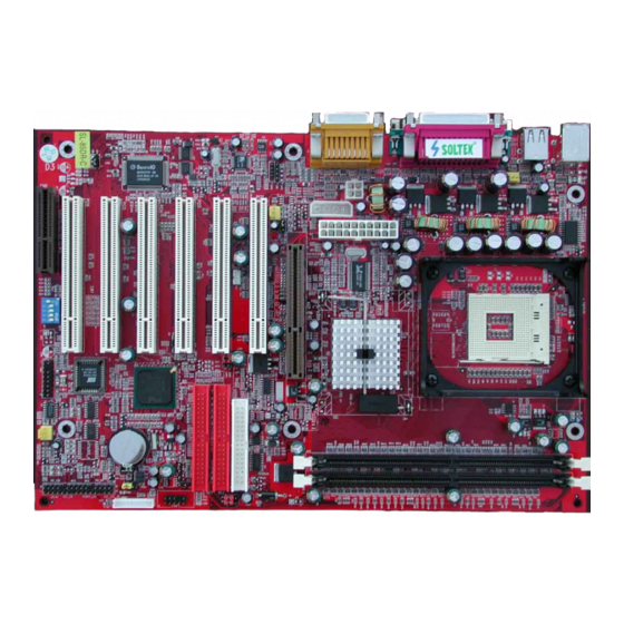
Page 12: Mainboard Layout
85DR-C 1-2 Mainboard Layout mPGA478B Intel RG82845 Intel RG82845-D AGP 4X FAN3 PCI 1 LED1 CD10 FDC1 JAGP1 JAGP2 AC'97 PCI 2 Codec WOL1 IDE2 PCI 3 IDE1 PCI 4 82801BA PCI 5 PCI 6 JP13 FAN1 USB1 1 2 3 4 5... -
Page 13: Chipset System Block Diagram
Chapter 1 Specification 1-3 Chipset System Block Diagram Intel Pentium 4 Processor System Bus (4x100MHz) Bandwidth 3.2GB/s Memory Interface Intel 82845-D System AGP 4x Memory (1.5V) PC133 SDRAM AGP Graphics 1.06GB/s -System Bus 1.06GB/s Controller -Memory Controller -AGP Controller -Hub Interface 2 IDE Drives Ultra DMA100/66 PCI Slots... - Page 14 85DR-C...
-
Page 15: Chapter 2 Hardware Setup
Chapter 2 Hardware Setup Chapter Hardware Setup To Get things ready for Hardware setup !!! 1. We recommend to install your CPU before any other componentes. For detailed installalation instructions of processor, you can also refer to the pamphlet enclosed in your CPU package. 2. -
Page 16: Pentium 4 Cpu Installation With Socket 478
85DR-C 2-1 Pentium 4 CPU Installation with Socket 478 This series of mainboards are built with CPU Socket 478 (with 478 pins) supporting the Intel Pentium 4 CPU: • Follow the steps described in this section to install the 478-pin Pentium 4 CPU into the on board Socket 478. -
Page 17: Pentium 4 Cpu Fan Installation
Chapter 2 Hardware Setup 2-2 Pentium 4 CPU Fan Installation: Pentium 4 Fan Socket Fan Connector Press down 4 latches to lock fan to fan socket Connect to CPU FAN connector... -
Page 18: Memory Installation
85DR-C 2-3 Memory Installation How to tackle with the memory Modules: • Make sure to unplug your power supply before adding or removing memory module. Failure to do so may cause severe damage to both your mainboard and the memory module. •... -
Page 19: Agp 4X (Accelerated Graphics Port) Installation
Chapter 2 Hardware Setup 2-4 AGP 4X (Accelerated Graphics Port) Installation Warning: • The AGP 4X slot on board supports solely 4X AGP card configuration. User should not insert 1X / 2X AGP card to this mainboard. • LED1 AGP Protection Indicator is on board this series. In case inappropriate AGP card (such as AGP 2X) is inserted into this AGP 4X Slot, LED1 will light up to warn that AGP installation is inproper. -
Page 20: Hdd/Fdd Installation
85DR-C 2-5 HDD/FDD Installation • To install HDD (Hard Disk Drive), you may connect the connector of IDE cable to the primary (IDE1) or secondary (IDE2) connector on board, and then connect the gray connector to your slave device and the black connector to your master device. - Page 21 Chapter 2 Hardware Setup • To install FDD (Floppy Disk Drive), you should connect the end of cable with single connector to the board , and connect the other end with two plugs to the floppy drives. mPGA478B Floppy Disk Drive Connector: Orient the red line on the floppy ribbon cable to Pin1.
-
Page 22: Jumper And Switch Settings
85DR-C 2-6 Jumper and Switch Settings • The following diagrams show the locations and settings of jumper blocks on the mainboard. Factory Test mPGA478B Only for factory test. Memory Module Voltage Select 2.5V (default) Intel RG82845 2.6V Intel RG82845-D AGP 4X FAN3 PCI 1 LED1... -
Page 23: 2-6.1 Switch 1 Cpu Clock Select
Chapter 2 Hardware Setup How to tackle with Jumpers: • Do not remove the jumper when power is on. Always make sure the power is off before changing any jumper settings. Otherwise, mainboard could be damaged. • In the Jumper setting diagram, all jumper pins covered with black marks stand for closed pins by jumper caps. -
Page 24: 2-6.2 Factory Test (By Jp2)
85DR-C 2-6.2 Factory Test (By JP2) Factory Test Only for factory test. 2-6.3 Memory Module Voltage Select (By JP3/JP4) This function allows you to select the voltage supplied to the DRAM. The default voltage (2.5V) should be used unless processor overclocking requires a higher voltage. -
Page 25: 2-6.4 Jp13 Memory Stick/Secure Digital Memory Card Reader Select
Chapter 2 Hardware Setup 2-6.4 JP13 Memory Stick/Secure Digital Memory Card Reader Select This jumper is designed on board for Memory Stick/Secure Digital Memory Card Reader select for CMEM1 connector. Memory Stick/Secure Digital Memory Card Reader Select Memry Stick Reader (Default) JP13 Secure Digital Memory Card JP13... -
Page 26: 2-6.6 Jbat1 Clear Cmos
85DR-C 2-6.6 JBAT1 Clear CMOS • When you have problem with rebooting your system, you can clear CMOS data and restore it to default value. To clear CMOS with Jumper JBAT1, please follow the steps below: (1) Power off system; (2) Set JBAT1 to Pin 2-3 closed. -
Page 27: Other Connectors Configuration
Chapter 2 Hardware Setup 2-7 Other Connectors Configuration • This section lists out all connectors configurations for users’ reference. 2-7.1 On Board FAN Connectors (FAN1,FAN2, FAN3) mPGA478B +12V SENSOR Intel RG82845 Intel RG82845-D AGP 4X FAN1, FAN2, FAN3: On-Board FAN Connectors FAN3 PCI 1 LED1... -
Page 28: 2-7.2 Wol1 Wake On Lan
85DR-C 2-7.2 WOL1 Wake On LAN mPGA478B Standby Ping Intel RG82845 Intel RG82845-D AGP 4X FAN3 PCI 1 LED1 CD10 Wake On LAN FDC1 JAGP1 JAGP2 AC'97 PCI 2 Codec WOL1 Connect the Wake On IDE2 PCI 3 IDE1 LAN signal from LAN PCI 4 WOL1 card to WOL1... -
Page 29: 2-7.3 Cd-Rom Audio Connector (Cd9/Cd10)
Chapter 2 Hardware Setup 2-7.3 CD-ROM Audio Connector (CD9/CD10) mPGA478B CD10 Intel RG82845 CD ROM Audio Connector Intel RG82845-D AGP 4X PIN NO. CD10 FAN3 PCI 1 LED1 CD10 FDC1 Right JAGP1 JAGP2 AC'97 PCI 2 PIN 1 Codec WOL1 Channel IDE2 PCI 3... -
Page 30: 2-7.4 Thermal Sensor Connector Rt2 (Optional)
85DR-C 2-7.4 Thermal Sensor Connector RT2 (Optional) mPGA478B RT1 mounted with blue Thermal Resistor. Intel RG82845 Intel RG82845-D AGP 4X FAN3 PCI 1 LED1 CD10 FDC1 JAGP1 JAGP2 AC'97 PCI 2 Codec WOL1 To RT2 IDE2 PCI 3 IDE1 PCI 4 To Devices 82801BA PCI 5... -
Page 31: 2-7.5 Complex Header Nj1
Chapter 2 Hardware Setup 2-7.5 Complex Header NJ1 • This complex Header consists of 10 connectors providing various supports: mPGA478B Intel RG82845 Intel RG82845-D AGP 4X FAN3 PCI 1 LED1 CD10 FDC1 JAGP1 JAGP2 AC'97 PCI 2 Codec WOL1 IDE2 PCI 3 IDE1 PCI 4... - Page 32 85DR-C 1. SMI Connector (System Management Interrupt): Connection: This 2-pin connector is connected to the case-mounted Suspend Switch. Function : Manually placing the system into a Suspend mode or “Green” mode. 2. Power Switch Connector: Connection: Connected to a momentary button or switch. Function : Manually switching the system between “On”...
-
Page 33: 2-7.6 Atx Power Supply Connectors Version 2.03 For Pentium 4
Chapter 2 Hardware Setup 2-7.6 ATX Power Supply Connectors version 2.03 for Pentium 4 • This mainboard is compatible with both ATX Power Supply Version 2.03 (with +12V Power Connector) and the older ATX Power Supply (with Peripheral Power Connector): Important: 1. -
Page 34: 2-7.7 Cmem1 Memory Stick™/Secure Digital Memory Card Reader Connector
85DR-C 2-7.7 CMEM1 Memory Stick™/Secure Digital Memory Card Reader Connector • This connector can be connected to a Memory Stick Reader or Secure Digital memory card reader with a Memory Stick/Secure Digital memory card cable connector. • JP13 is designed on board for Memory Stick/Secure Digital memory card select for this connector. -
Page 35: 2-7.8 Communication And Networking Riser Slot (Cnr)
Chapter 2 Hardware Setup 2-7.8 Communication And Networking Riser Slot (CNR) • This slot allows you to use network, modem or audio riser cards. mPGA478B Intel RG82845 Intel RG82845-D AGP 4X FAN3 PCI 1 LED1 CD10 FDC1 JAGP1 JAGP2 AC'97 PCI 2 Codec WOL1... -
Page 36: 2-7.9 Smart Card Reader Connector (Scr1)
85DR-C 2-7.9 Smart Card Reader Connector (SCR1) • The connector “SCR1” allows you to use Smart Card Reader. It is compliant with Personal Computer Smart Card (PC/SC) working group standard and smart card (ISO 7816) protocols. mPGA478B RWLED PSNT Intel RG82845 Intel RG82845-D AGP 4X FAN3... -
Page 37: 2-7.10 Usb Header (Header Usb1)
Chapter 2 Hardware Setup 2-7.10 USB Header (Header USB1) • This header is for providing you two additional USB ports by using an additional USB Cable. User can order the additional USB cable from your mainboard dealers and venders. mPGA478B Additional USB Cable (Optional) Intel RG82845... -
Page 38: 2-7.12 Chassis Panel Connector
85DR-C 2-7.12 Chassis Panel Connector A : PS/2 MOUSE PORT B : USB 0 PORT C : LPT1 PORT D : GAME/MIDI PORT E : PS/2 KEYBOARD PORT F : USB 1 PORT G : COM1 PORT H : COM2 PORT : LINE/SPEAKER OUT J : LINE IN K : MICROPHONE INPUT... -
Page 39: Irq Description
Chapter 2 Hardware Setup 2-8 IRQ Description Function Description Priority IRQ 0 System Timer IRQ 1 Keyboard Controller IRQ 2 Programmable Interrupt IRQ 3 Serial Port (COM 2) IRQ 4 Serial Port (COM 1) IRQ 5 IRQ 6 Floppy Disk Controller IRQ 7 Parallel Port (LPT1) IRQ 8... - Page 40 85DR-C...
-
Page 41: Chapter 3 Software Setup
Chapter 3 Software Setup C hapter Software Setup Drivers, Utilities and Software Installation • Support CD: This series of mainboards will always be shipped with a Support CD which contains those necessary driver files, Application Softwares and some helpful utilities. It is a user-friendly, auto-run CD which will open itself up in a CD-ROM automatically. -
Page 42: Open Up The Support Cd And Choose Drivers And Utilities
85DR-C 3-1 Open up the Support CD and choose Drivers and Utilities Please put the Support CD enclosed in your mainboard package into the CD-ROM drive. In a few seconds, the Main Menu will automatic-ally appear, displaying the contents to be installed for this series: Intel Chipset Software Installation Utility (INF Utility) Intel Application Accelerator (IAA) -
Page 43: Install "Intel Chipset Software Installation Utility
Chapter 3 Software Setup 3-2 Install “Intel Chipset Software Installation Utility” Following the procedures of opening the Support CD, click to “ Install Intel Chipset software installation Utility” to proceed. The Intel Service Pack InstallShield Wizard will pop up to guide you to the Intel Service pack installation. -
Page 44: Install "Intel Application Accelerator
85DR-C 3-3 Install “Intel Application Accelerator” IAA supports all Windows 98/98se/Mellennium/NT4/2000/XP with Pentium III / 4 processor. Installations of this software for these operating systems are similarly programed to an auto-run mode, and it is typically designed to improve performance of the storage sub- system and overall system performance. - Page 45 Chapter 3 Software Setup On ”Choose Destination Location” screen, press “Yes” to continue. C:\Program Files\Intel\Intel Application Accelerator On ”InstallShield Wizard Com-plete” screen, choose “Yes, I want to restart my Yes, I want to restart my computer now computer now” and press “finish”...
-
Page 46: Ac'97 Audio Driver Installation
85DR-C 3-4 AC’97 Audio Driver Installation You can install “ AC’97 Audio Driver” on these two members of the series. Following the procedures of opening the Support CD, click to “ AC’97 Audio Driver” to proceed. When the “Avance AC’97 Drivers and Applications”... -
Page 47: Install Hardware Monitor Utility
Chapter 3 Software Setup 3-5 Install Hardware Monitor Utility 3-5.1 Installation Hardware Monitor is built on this mainboard. Its installation is programed to a fully automated mode on Windows 9X/Me/NT4/2000/ XP. User can follow the model installation below for its installation on various Windows System. -
Page 48: 3-5.2 Verification
85DR-C 3-5.2 Verification A f t e r r e s t a r t i n g y o u r computer, click “Start” and choose the path Programs \Winbond\Hwdoctor to open the main window of the Hardware Doctor. The “Voltage/CaseOpen”... - Page 49 Chapter 3 Software Setup...
-
Page 50: Chapter 4 Bios Setup
85DR-C Chapter BIOS Setup THE BIOS • BIOS stands for Basic Input and Output System. It was once called ROM BIOS when it was stored in a Read-Only Memory(ROM) chip Now manufacturers would like to store BIOS in EEPROM which means Electrically Erasable Programmable Memory. -
Page 51: About Bios Setup
Chapter 4 BIOS Setup 4-1 About BIOS Setup • BIOS setup is an interactive BIOS program that you need to run when: 1. Changing the hardware of your system. (For example: installing a new Hard Disk etc.) 2. Modifying the behavior of your computer. (For example: changing the system time or date, or turning special features on or off etc.) 3. -
Page 52: To Upgrade Bios
85DR-C 4-5 To upgrade BIOS • System BIOS is incorporated into a Flash memory component. Flash BIOS allows user to upgrade BIOS without the need to replace an EPROM component. • The Upgrade Utility can be loaded on a floppy diskette to execute saving, verifying, and updating the system BIOS. - Page 53 Chapter 4 BIOS Setup Step 4. Type AMIFLASH *.ROM and then press <Enter> to run BIOS upgrade program. (*.ROM depends on your mainboard model and version code. Instead of typing “*”, you should type specific file name for your specific mainboard). Step 5.
-
Page 54: Bios Setup
85DR-C 4-6 BIOS Setup --- CMOS Setup Utility 4-6.1 CMOS Setup Utility • This mainboard comes with the AMI BIOS from American Megatrends Inc. Enter the CMOS Setup Utility Main Menu by: 1. Turn on or reboot your system. After a series of diagnostic checks, the following message will appear: PRESS <DEL>... -
Page 55: 4-6.2 Standard Cmos Setup
Chapter 4 BIOS Setup 4-6.2 Standard CMOS Setup • Standard CMOS Setup records some basic system hardware configuration and sets the system clock and error handling. You only need to modify the configuration values of this option if you want to change your system hardware configuration or when the data stored in the CMOS memory gets lost or damaged. - Page 56 85DR-C System Time The BIOS shows the time of the day in the format: hh:mm:ss. Choose the field with the Arrow keys and change the time with the Page Up/Page Down keys. System Date The BIOS shows the date of the day in the format: mm:dd:yy :day of the Week.
- Page 57 Chapter 4 BIOS Setup Type This option shows the types of configuration for the IDE devices: 1-50: Predefined types USER: set Parameters by User Auto: Set parameters automatically CD-ROM: Use for ATAPI CD-ROM drives Double click [Auto] to set all HDD parameters automatically, including “Cylinders, Heads, Write Precompensation, Sectors, Maximum Capacity and 32 Bit Transfer Mode.
-
Page 58: 4-6.3 Advanced Bios Features
85DR-C 4-6.3 Advanced BIOS Features • Advanced BIOS Features improves your system performance or sets up system features according to your preference. Run the Advanced BIOS Features as follows: 1. Choose “Advanced BIOS Features” from the Main Menu and a screen with a list of options will appear: AMIBIOS EASY SETUP UTILITY - VERSION 2.01A Advanced BIOS Features... - Page 59 Chapter 4 BIOS Setup 2. Use one of the arrow keys to move between options and modify the selected options by using PgUp / PgDn / + / - keys. An explanation of the <F> keys follows: <F1>: “Help” gives options available for each item. <F9>: Setup BIOS default values.
- Page 60 85DR-C Boot Up Floppy Seek When enabled, the BIOS tests (seeks) floppy drives to determine whether they have 40 or 80 tracks. Only 360-KB floppy drives have 40 tracks; drives with 270KB, 1.2MB, and 1.44MB capacity all have 80 tracks. Because very few modern PCs have 40-track floppy drives, we recommend that you set this field to disabled to save time.
- Page 61 Chapter 4 BIOS Setup C000, 32K Shadow Allows you to set these addresses cached, Enabled or Disabled. Default: Cached C800,CC00,D000,D400, Allows you to set these addresses cached, Enabled or D800,DC00 16K Disabled. Default: Disabled Shadow...
-
Page 62: 4-6.4 Advanced Chipset Features
85DR-C 4-6.4 Advanced Chipset Features • Advanced Chipset Features is used to modify the values of chipset buffers. These buffers control the system options. Run the Advanced Chipset Features as follows: 1. Choose “Advanced Chipset Features” from the Main Menu and a list of option will appear: AMIBIOS EASY SETUP UTILITY - VERSION 2.01A Advanced Chipset Features... - Page 63 Chapter 4 BIOS Setup 3. Press <ESC> to return to the Main Menu when you finish setting up all items. The following item descriptions are provided as a quick guide to your setup. SDRAM Frequency The value represents the performance parameters of the installed memory chips (DRAM).
- Page 64 85DR-C SDRAM RAS# to CAS# This field lets you insert a timing delay between the Delay CAS and RAS strobe signals, used when DRAM is written to, read from, or refreshed. Fast gives faster performance and Slow gives more stable performance.
- Page 65 Chapter 4 BIOS Setup USB Controller Select Enabled if your system contains a Universal Serial Bus (USB) controller and you have USB peripherals. USB Device Legacy Set this option to Enabled to support for Legacy USB Support devices. Port 64/60 Please leave this field at default setting.
-
Page 66: 4-6.5 Power Management Setup
85DR-C 4-6.5 Power Management Setup • Power Management Setup allows you to set the system’s power saving functions. Run the Power Management Setup as follows: 1. Choose “Power Management Setup” from the Main Menu and a list of options will appear: AMIBIOS EASY SETUP UTILITY - VERSION 2.01A Power Management Features [Setup Help]... - Page 67 Chapter 4 BIOS Setup 2. Use one of the arrow keys to move between options and modify the selected options by using PgUp / PgDn / + / - keys. An explanation of the <F> keys follows: <F1>: “Help” gives options available for each item. <F9>: Setup BIOS default values.
- Page 68 85DR-C Power Management/ This option allows you to select the type (or degree) of power saving for Doze, Standby, and Suspend modes. This table describes each power management mode. Default: User Define. Maximum power savings. Only Available for SL CPUs. Max Saving Inactivity period is 1 minute in each mode.
- Page 69 Chapter 4 BIOS Setup This option allows you to Disable to Enable on board Primary/Second Primary/Second IDE controller. Master/Slave IDE Power Button Function This option specifies how the power button mounted externally on the computer chassis is used. Restore on AC/Power This function allows you to set whether or not to Loss restart the system after power interruptions.
-
Page 70: 4-6.6 Pnp / Pci Configuration
85DR-C 4-6.6 PNP / PCI Configuration • PNP/PCI Configuration allows you to modify the system’s power saving functions. Run the PNP/PCI Configuration as follows: 1. Choose “PNP/PCI Configuration” from the Main Menu and a screen with a list of options will appear: AMIBIOS EASY SETUP UTILITY - VERSION 2.01A PNP/PCI Configurations [Setup Help]... - Page 71 Chapter 4 BIOS Setup Plug & Play aware O/S Select Yes for Windows systems supporting Plug and Play function. Select No for systems not supporting PNP. Clear NVRAM This function allows you to turn on the system through a Ethernet Card. PCI Latency Timer (PCI Please leave this field to the default setting for best Clocks)
-
Page 72: 4-6.7 Integrated Peripherals
85DR-C 4-6.7 Integrated Peripherals • Integrated Peripherals option allows you to get some information inside your system when it is working. Run the Integrated Peripherals as follows: 1. Choose “Integrated Peripherals” from the Main Menu and a list of options will appear: AMIBIOS EASY SETUP UTILITY - VERSION 2.01A Integrated Peripherals... - Page 73 Chapter 4 BIOS Setup 2. Use one of the arrow keys to move between options and modify the selected options by using PgUp / PgDn / + / - keys. An explanation of the <F> keys follows: <F1>: “Help” gives options available for each item. <F9>: Setup BIOS default values.
- Page 74 85DR-C OnBoard Serial PortA/ Allows you to set Serial Port on board. Select a logi- PortB cal COM port name and matching address for the first and second serial ports. Select an address and corresponding interrupt for the first and second serial ports. The choices: Auto;...
- Page 75 Chapter 4 BIOS Setup Parallel Port IRQ/DMA If Parallel Port is set 378h, this option allows you to configure parallel port IRQ/DMA. The choices: 5/7 for IRQ; 0/1/3 for DMA OnBoard MIDI Port Allows you to configure onboard MIDI port . The choices: Disabled;...
-
Page 76: 4-6.8 Hardware Monitor Status Features
85DR-C 4-6.8 Hardware Monitor Status Features • This section helps you to get more information about your system including CPU temperature, FAN speed and voltage. It is recommended that you contact your mainboard supplier to get proper values about the setting of the CPU temperature. - Page 77 Chapter 4 BIOS Setup Shutdown Temperature This feature prevents your CPU from damage by over heat. If the CPU’s temperature is higher than “CPU warning temperature” that you select in this field, the BIOS will shut down your system within 3 seconds.
-
Page 78: 4-6.9 Frequency/Voltage Control
85DR-C 4-6.9 Frequency/Voltage Control Run the “Frequency/Voltage Control” as following: 1. Choose “Frequency/Voltage Control” from the Main Menu and a screen with a list of options will appear: AMIBIOS EASY SETUP UTILITY - VERSION 2.01A Frequency/Voltage Control [Setup Help] RedStorm Overclocking Tech (Option) Please press 'Enter' CPU Linear Freq... - Page 79 Chapter 4 BIOS Setup Redstorm Please press <Enter> to start RED STORM OVER- Overclocking CLOCKING TECH, this option helps user an easy Tech (Option) way to overclocking, it will increase CPU external clock automatically, when CPU external clock increasing to unacceptable value, BIOS will restart your system, then running at acceptable CPU external clock.
-
Page 80: 4-6.10 Set Supervisor / User Password
85DR-C 4-6.10 Set Supervisor / User Password These two options allow you to set your system passwords. Normally, the Supervisor Password should be set up first before you could go to set up the User Password. : 1. Choose “Set Supervisor Password” in the Main Menu and press <Enter>. -
Page 81: 4-6.11 Load Optimized Defaults
Chapter 4 BIOS Setup 10. After pressing <Enter>, the following message appears to confirm the new user password. [ New user password installed ] 11. Move the cursor to Save & Exit Setup to save the password. 12. If you need to delete the password entered before, choose the Su- pervisor Password and press <Enter>. -
Page 82: 4-6.12 Save & Exit Setup
85DR-C 4-6.12 Save & Exit Setup Save & Exit Setup allows you to save all modifications you have specified into the CMOS memory. Highlight this option on the Main Menu and the following message appears: [ Saving current settings and exit ] Press [Enter] to continue or [ESC] to abort Press <Enter>... - Page 83 Chapter 4 BIOS Setup...
-
Page 84: Appendices
85DR-C Appendices Appendix-1 IDENTIFYING BIOS VERSION/ BIOS PART NUMBER Appendix-2 TECHNICAL TERMS... -
Page 85: Appendix-1 Identifying Mainboard Model Number
Chapter 4 BIOS Setup Appendix-1 Identifying Mainboard model Number • Usually the mainboard model number is labeled on the side of ISA side of slot or PCI slot. Please see the picture below as an illustration: MAINBOARD MODEL NUMBER example: SL-65KV2 MAINBOARD SERIAL NUMBER example: 0012000T005679... -
Page 86: Appendix-2 Technical Terms
85DR-C Appendix-2 Technical Terms AC’97 AC’97 is a device designed to include a digital processor for modem and an audio CODEC for analog I/O. These two parts are linked together by AC’97 link bus. Putting the digital processor into the main system chipset will reduce the cost of sound/modem onboard solution. - Page 87 Chapter 4 BIOS Setup ATAPI (AT Attachment Packet Interface) This is the extension of the EIDE (extended IDE) that enables the interface to support CD-ROM players and tape drives. BIOS (Basic Input/Output System) BIOS is a set of assembly routine/program that resides in EPROM or Flash ROM.
- Page 88 85DR-C DIMM (Dual In Line Memory Module) DIMM socket is built with a 168-pin assignment and supports 64-bit data. DIMM can be single or double sided. The golden finger signals on each side of the module are different, and that is why it is called Dual In Line. Almost all DIMMs are made with SDRAM now, which operate at 3.3V.
- Page 89 Chapter 4 BIOS Setup FC-PGA (Flip Chip-Pin Grid Array) FC means Flip Chip, while FC-PGA is a new package of Intel for Pentium III CPU. It is compatible with SKT370 socket, but requires mainboard to add some signals on socket 370. Flash ROM Flash ROM can be reprogrammed by electronic signals.
- Page 90 85DR-C PC-1600 or PC-2100 DDR SDRAM PC-1600 DDR SDRAM with a 64-bit data bus doubles the data transfer rate of PC100 SDRAM and hence provides data transfer bandwidth up to 100x64/ 8x2=1600MB/s. PC2100 DDR SDRAM doubles the data transfer rate of PC-133 and hence provides data transfer bandwidth up to 133x64/ 8x2=2100MB/s.
- Page 91 Chapter 4 BIOS Setup SDRAM (Synchronous DRAM) SDRAM is one of the Dynamic Random Access Memory (DRAM) technologies that allow DRAM to use the same clock as the CPU host clock (EDO and FPM are asynchronous and do not have clock signal). SDRAM comes in 64-bit 168-pin DIMM and operates at 3.3V.
- Page 92 85DR-C USB (Universal Serial Bus) USB is a 4-pin serial peripheral bus that is capable of cascading low/medium speed peripherals (less than 10Mbit/s) such as keyboard, mouse, joystick, scanner, printer and modem. VCM (Virtual Channel Memory) NEC’s Virtual Channel Memory (VCM) is a new DRAM core architecture that dramatically improves the memory system’s ability to service multimedia requirements.
- Page 93 Chapter 4 BIOS Setup...
Need help?
Do you have a question about the SL-85DR-C and is the answer not in the manual?
Questions and answers