Table of Contents
Advertisement
Quick Links
85DRV4-C
Chapter 1 Specification ............................................. 9
1-1 85DRV4-C Components and Options ................................ 10
1-2 Mainboard Specifications ..................................................... 11
1-2.1 CPU Socket ................................................................................... 11
1-2.2 System Chipsets ........................................................................... 11
1-2.3 Memory ......................................................................................... 11
1-2.4 Award BIOS .................................................................................. 11
1-2.5 Accelerated Graphics Port (AGP) Interface ........................... 11
1-2.6 Advanced System Power Management: ................................... 12
1-2.7 Multi-I/O Functions : .................................................................. 12
1-2.8 Expansion Slots ............................................................................ 12
1-2.9 AC'97 Audio Codec on board ................................................... 13
1-2.10 Hardware Monitor on board ................................................... 13
1-2.11 Form Factor ................................................................................ 13
1-3 Mainboard Specification Table ........................................... 14
1-4 Chipset System Block Diagram ........................................... 15
Chapter 2 Hardware Setup ..................................... 16
2-1 CPU Installation with Socket 478B .................................... 17
2-2 Pentium 4 CPU Fan Installation ......................................... 18
2-3 Memory Installation ............................................................. 19
2-3.1 To Install DDR SDRAM Module .............................................. 19
2-3.2 To Remove a DIMM .................................................................... 20
2-4 AGP 4X/2X Slot Installation ................................................ 21
2-5 IDE Connector Installation ................................................. 22
2-6 Floppy Drive Connector ( FDC ) Installation ................. 23
2-7 ATX V2.03 Power Supply Installation ............................... 24
2-8 Jumper and Switch Settings ................................................ 25
Contents
4
Advertisement
Table of Contents

Related Manuals for SOLTEK 85DRV4-C


Summary of Contents for SOLTEK 85DRV4-C
-
Page 1: Table Of Contents
85DRV4-C Contents Chapter 1 Specification ..........9 1-1 85DRV4-C Components and Options ........ 10 1-2 Mainboard Specifications ............. 11 1-2.1 CPU Socket ................... 11 1-2.2 System Chipsets ................11 1-2.3 Memory ..................11 1-2.4 Award BIOS .................. 11 1-2.5 Accelerated Graphics Port (AGP) Interface ......11 1-2.6 Advanced System Power Management: ........ - Page 2 Contents 2-8.1 Jp1 and SW1: CPU Clock/Overclock Select ......26 2-8.2 JBAT1: Clear CMOS ..............28 2-8.3 Jp2: Flash ROM Write Protection ........... 28 2-9 Other Connectors Configuration ........29 2-9.1 On-board FAN Connectors ............29 2-9.2 Connector WOL1: Wake On LAN ..........30 2-9.3 CD-ROM Audio Connector (CD1) ...........
- Page 3 85DRV4-C 4-5.2 Update Process ................48 4-6 BIOS SETUP --- CMOS Setup Utility ........ 51 4-6.1 CMOS Setup Utility ..............51 4-6.2 Standard CMOS Setup ............... 52 4-6.3 Advanced BIOS Features ............55 4-6.4 Advanced Chipset Features ............59 4-6.5 Integrated Peripherals ..............65 4-6.6 Power Management Setup ............
- Page 4 85DRV4-C ITEM CHECKUP Mainboard Support CD Bundled Bonus Pack CD Bundled Bonus Pack Manual Temperature Sensor Cable (Optional) ATA66/100/133 IDE Cable FDD Cable User Manual RS232 Cable (optional) USB Cable (optional)
-
Page 5: Chapter 1 Specification
Chapter 1 Specification Chapter 1 Specification Introduction This Mainboard features an integration of the powerful processor In- tel Pentium 4 and the single-chip North Bridge VIA Apollo P4X266E plus South Bridge VT8233A, by which the whole system performance can be upgraded to 533MHz system bus. The Intel P4 processor is a rapid execution engine providing 4X100/ 4X133MHz quadpumped system bus to allow 3.2GB data transfer rates possible, while VIA Apollo P4X266E plus VT8233A supports Intel P4... -
Page 6: 85Drv4-C Components And Options
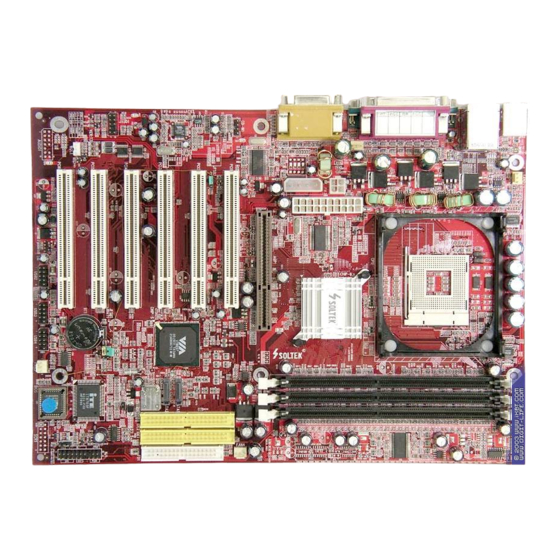
85DRV4-C 1-1 85DRV4-C Components and Options PS/2 Mouse (on top) PS/2 K/B (underside) USB0 (on top) USB1 (underside) Main Power Connector P4x266E Peripheral Power AGP 4X/2X Connector PCI 1 PCI 2 PCI 3 AC'97 Codec VT8233A Audio Codec PCI 4... -
Page 7: Mainboard Specifications
Chapter 1 Specification 1-2 Mainboard Specifications 1-2.1 CPU Socket ® CPU Socket 478B on board, supporting Intel Pentium 4 processors in 478-pin package for : -- 533/400MHz System Bus; -- Hyper-pipelined technology; -- Advanced dynamic execution; -- Advanced transfer cache; 1-2.2 System Chipsets •... -
Page 8: 1-2.6 Advanced System Power Management
85DRV4-C 1-2.6 Advanced System Power Management: • ACPI 1.0B compliant (Advanced Configuration and Power Interface) • APM V1.2 compliant (Legacy Power Management) • ACPI POS (Power On Suspend) • PS/2 Keyboard & Mouse Power On • Supporting Ring Power Up Control for Wake-on-LAN (via Connector WOL1) •... -
Page 9: 1-2.9 Ac'97 Audio Codec On Board
Chapter 1 Specification 1-2.9 AC’97 Audio Codec on board • AC’97 Audio Codec, 2-channel Audio supported • AC’97 Audio Codec Driver enclosed in Support CD for user’s install- ation. 1-2.10 Hardware Monitor on board • Hardware Monitor integrated in Super I/O IT8705F, providing moni- toring and alarm for flexible desktop management of hardware voltage, temperatures and fan speeds. -
Page 10: Mainboard Specification Table
85DRV4-C 1-3 Mainboard Specification Table SL-85DRV4-C Specifications and Features Socket 478B for Intel Pentium 4 CPUs North Bridge VIA P4X266E, supporting 533/400MHz FSB South Bridge VIA VT8233A BIOS AwardBIOS Memory Supporting DDR 266/200 SDRM, up to 3GB in 3 DDR DIMM slots... -
Page 11: Chipset System Block Diagram
Chapter 1 Specification 1-4 Chipset System Block Diagram Intel Pentium 4 478-pin package 533/400 MHz FSB P4x266E DDR 266/200 Memory Bus AGP 4X/2X Bus Single-chip Slot North Bridge SDRAMs 266MB/sec V-Link BIOS PCI Slots PCI Bus Game Port Serial / IR VT8233A Parallel Super I/O... -
Page 12: Chapter 2 Hardware Setup
85DRV4-C Chapter 2 Hardware Setup To Get things ready for hardware setup ! 1. We recommend to install your CPU before any other components. For detailed installation instructions of processor, you can also refer to the pamphlet enclosed in your CPU package. -
Page 13: Cpu Installation With Socket 478B
Chapter 2 Hardware Setup 2-1 CPU Installation with Socket 478B This series is built with CPU Socket 478B ( 478-pin) supporting the Intel Pentium 4 CPU: • Follow the steps described in this section to install the 478-pin Pen- tium 4 CPU into the on board Socket 478. •... -
Page 14: Pentium 4 Cpu Fan Installation
85DRV4-C 2-2 Pentium 4 CPU Fan Installation Pentium 4 Fanbase CPU Fan Connector Press down 4 corners to lock fan to fanbase Connect Fan Connector to CPU FAN connector... -
Page 15: Memory Installation
Chapter 2 Hardware Setup 2-3 Memory Installation How to tackle the memory Modules: • Make sure to unplug your power supply before adding or removing memory module. Failure to do so may cause severe damage to both your mainboard and the memory module. •... -
Page 16: 2-3.2 To Remove A Dimm
85DRV4-C 2-3.2 To Remove a DIMM Power off system and press down the holding latches on both sides of slot to release the module from the DIMM slot. D D R D I M M S l o t s... -
Page 17: Agp 4X/2X Slot Installation
Chapter 2 Hardware Setup 2-4 AGP 4X/2X Slot Installation The AGP slot on board supports AGP4X(1.5) / 2X(3.3V) card. An AGP 4X card will support a data transfer rate up to 1GB/sec., while an AGP 2X card will do up to 0.5GB/sec only. AGP Accelerator AGP 4X / 2X PS/2 Mouse... -
Page 18: Ide Connector Installation
85DRV4-C 2-5 IDE Connector Installation To install IDE Connector, you may connect the blue connector of IDE cable to the primary (IDE1) or secondary(IDE2) connector on board, and then connect the gray connector to your slave device and the black connector to your master device. -
Page 19: Floppy Drive Connector ( Fdc ) Installation
Chapter 2 Hardware Setup 2-6 Floppy Drive Connector ( FDC ) Installation To install FDC (Floppy Drive Connector), you should connect the end of FDC cable with single connector to the board , and connect the other end with two connectors to the floppy drives. PS/2 Mouse (on top) PS/2 K/B... -
Page 20: Atx V2.03 Power Supply Installation
85DRV4-C 2-7 ATX V2.03 Power Supply Installation +12V Power Connector Pin1 Pin11 +12V +12V +12V PWR_OK PS/2 Mouse (on top) PS/2 K/B (underside) USB0 (on top) PS_ON# USB1 (underside) -12V +3.3V +3.3V +3.3V Main Power Connector P4x266E Main Power Connector... -
Page 21: Jumper And Switch Settings
Chapter 2 Hardware Setup 2-8 Jumper and Switch Settings The following diagrams show the locations and settings of Switch and jumper blocks on the mainboard. Jp1: Overclock Select Overclock setting CPU Clock Select to Boot System Off On On On (Default) 100/103/107/111SW1 CPU clock... - Page 22 85DRV4-C How to tackle the Jumpers: A 3-pin Jumper If a pin-header (of 2 or more pins) is designed in such a way that its pins can be closed or linked together to A 2-pin Jumper cap to link set up a specific function, this header two header-pins together.
- Page 23 Chapter 2 Hardware Setup Jp1: Overclock Select Overclock setting CPU Clock Select to Boot System Off On On On (Default) CPU clock 100/103/107/111SW1 (MHz) setting for 100MHz 1-2 closed (default) CPU to boot system; (default) CPU Auto-detect 133MHz SW1 setting for 133MHz CPU to 100 / 133MHz boot system;...
- Page 24 85DRV4-C 2-8.2 JBAT1: Clear CMOS When you have problem with rebooting your system, you can clear CMOS data and restore it to default value. To clear CMOS with Jumper JBAT1, please follow the steps below: 1. Power off system. 2. Set JBAT1 to Pin 2-3 closed.
- Page 25 Chapter 2 Hardware Setup 2-9 Other Connectors Configuration This section lists out all connectors configurations for users’ reference. 2-9.1 On-board FAN Connectors Void +12V PS/2 Mouse (on top) PS/2 K/B +12V (underside) USB0 (on top) SENSOR USB1 (underside) Sensor Conn. No Sensor Main Power Connector...
- Page 26 85DRV4-C 2-9.2 Connector WOL1: Wake On LAN 1. This connector connects to a LAN card with a Ring signal output. The connector powers up the system when it receives a wake-up packet or signal through the LAN card. 2. This feature requires that Resume On Ring feature is enabled in the BIOS setting “Power Management Setup”...
- Page 27 Chapter 2 Hardware Setup 2-9.4 Chassis Panel Connectors G : COM1 Port A : PS/2 MOUSE PORT H : COM2 PORT B : USB 0 (0n top) : LINE Out C : LPT1 PORT J : LINE IN D : GAME/MIDI PORT K : MICROPHONE INPUT E : PS/2 KEYBOARD PORT F : USB 1 PORT (Bottom)
- Page 28 85DRV4-C 2-9.6 USB Ports and USB Pin-Headers This Mainboard provides two USB ports USB0 and USB1 on board supporting various USB devices. In addition, Pin-Header JUSB1 is added on board to provide expansion of 2 more optional USB ports by using one additional USB Cables.
- Page 29 Chapter 2 Hardware Setup 2-9.7 Thermal Sensor Connectors RT1 and RT2 PS/2 Mouse (on top) PS/2 K/B (underside) USB0 (on top) RT1 will be mounted USB1 (underside) with Thermal Resistor by default. Main Power Connector P4x266E Peripheral Power AGP 4X/2X Connector PCI 1 To Devices...
- Page 30 85DRV4-C 2-9.8 Complex Pin-header (Front Panel Connector) This complex Pin-header consists of the following connectors for vari- ous supports. When you have fixed the mainboard to the case, join the connectors of this Complex Pin-header to the case Front Panel.
- Page 31 Chapter 2 Hardware Setup (1) SMI Connector (Optional): Connection: Connected to the case-mounted Suspend Switch. Function: Manually selecting system into the Suspend Mode or “Green Mode” by System management interrupt. (2) Power Switch Connector: Connection: Connected to a momentary button or switch. Function: Manually switching the system between “On”...
- Page 32 85DRV4-C 2-9.9 CD-ROM Audio Connectors (CD 1) CD 1 is an audio connector connecting CD-ROM audio to mainboard. PS/2 Mouse (on top) PS/2 K/B (underside) USB0 (on top) USB1 (underside) CD-ROM Audio Connector Main Power Connector P4x266E CD 1 Pin 1...
- Page 33 Chapter 2 Hardware Setup 2-10 IRQ Description Function Description Priority IRQ 0 System Timer IRQ 1 Keyboard Controller IRQ 2 Programmable Interrupt IRQ 3 Serial Port (COM 2) IRQ 4 Serial Port (COM 1) IRQ 5 Free IRQ 6 Floppy Disk Controller IRQ 7 Parallel Port (LPT1) IRQ 8...
- Page 34 85DRV4-C Chapter 3 Software Setup Drivers, Utilities and Software Installation Support CD: This mainboard will be shipped with a Support CD which contains those necessary driver files, Application Softwares and some helpful utilities. It is a user-friendly, auto-run CD which will open itself up in a CD-ROM automatically.
- Page 35 Chapter 3 Software Setup 3-1 Open Up Support CD: 1. Please put the Support CD enclosed in your mainboard package into the CD-ROM drive. In a few seconds, the Main Menu will automatic ally appear, displaying the contents to be installed for this series: Install VIA 4-in-1 Driver Install VIA AC’97 Audio Driver...
- Page 36 85DRV4-C 3-2 Proceed to VIA 4-IN-1 Drivers Installation 1. Following the procedures of opening the Support CD, click to “ VIA 4- in-1 Drivers” to proceed. 3. “VIA Service Pack README” 2 . T h e V I A S e r v i c e P a c k...
- Page 37 Chapter 3 Software Setup 7. Click on “Click to enable DMA 6 . S e l e c t “ I n s t a l l V I A ATA P I Mode” checkbox to enable V e n d o r S u p p o r t D r i v e r ” DMA function, then click the checkbox, then click the “Next”...
- Page 38 85DRV4-C 3-3 Proceed to AC’97 AUDIO Driver Installation 1. Following the installation of VIA 4-in-1 drivers, you have to restart system so that your system can be reconfigured with VIA 4-in-1. When restarting procedures finish, please open the Support CD with your CD-ROM to enter the Main Installation Menu.
- Page 39 Chapter 3 Software Setup 3-4 Proceed to Hardware Monitor Installation 3-4.1 Installation Hardware Monitor is built in chip IT8705F of this series. Its in- stallation is programed to a fully automated mode on Windows 9X/ Me/NT4/2000/XP. User can follow the model installation below for its installation on various Windows System.
- Page 40 85DRV4-C 3-4.2 Verification 1. After restarting your computer, click “Start” and choose the path \ P r o g r a m s \ I T E S m a r t Accessories\ITE Smart Guardian to open the main window of the Hardware Doctor.
Need help?
Do you have a question about the 85DRV4-C and is the answer not in the manual?
Questions and answers