Table of Contents
Advertisement
Quick Links
85MR3 / 85MR3-L
Chapter 1 Specification ............................................. 9
1-1 Mainboard Layout ................................................................ 10
1-2 Mainboard Specifications ..................................................... 11
1-2.1 CPU Socket ................................................................................... 11
1-2.2 System Chipsets ........................................................................... 11
1-2.3 Memory ......................................................................................... 11
1-2.4 AMI BIOS ..................................................................................... 11
1-2.5 Accelerated Graphics Port (AGP) Interface ........................... 11
1-2.6 2D/3D VGA on board .................................................................. 12
1-2.7 Advanced System Power Management .................................... 12
1-2.8 Multi-I/O Functions .................................................................... 12
1-2.9 Expansion Slots ............................................................................ 12
1-2.10 LAN on board (for 85MR3-L only) ........................................ 13
1-2.11 Hardware Monitor on board ................................................... 13
1-2.12 AC'97 Audio Codec on board .................................................. 13
1-2.13 6-channel Audio-out Support (optional) ............................... 13
1-2.14 Form Factor ................................................................................ 13
1-3 Mainboard Specification Table ........................................... 14
1-4 Chipset System Block Diagram ........................................... 15
Chapter 2 Hardware Setup ..................................... 16
2-1 CPU Identification and Installation ................................... 17
2-1.1 To Identify a Pentium 4 CPU ..................................................... 17
2-1.2 CPU Installation with Socket 478B .......................................... 18
2-2 Pentium 4 CPU Fan Installation ......................................... 19
2-3 Memory Installation ............................................................. 20
2-3.1 To Install/Remove DDR DRAM Module ................................. 20
2-3.2 Indicator LED1: DIMM Powered On ...................................... 21
Contents
4
Advertisement
Table of Contents

Related Manuals for SOLTEK 85MR3


Summary of Contents for SOLTEK 85MR3
-
Page 1: Table Of Contents
1-2.7 Advanced System Power Management ........12 1-2.8 Multi-I/O Functions ..............12 1-2.9 Expansion Slots ................12 1-2.10 LAN on board (for 85MR3-L only) ........13 1-2.11 Hardware Monitor on board ........... 13 1-2.12 AC’97 Audio Codec on board ..........13 1-2.13 6-channel Audio-out Support (optional) ....... - Page 2 2-8.1 Jp4: CPU Clock Select ..............27 2-8.2 JBAT1: Clear CMOS ..............28 2-8.3 JP1: KB /Mouse / Power Button Select ........29 2-8.4 Jp10: LAN Controller Select (85MR3-L only) ....... 29 2-8.5 Jp11: VGA/AGP 4X Safeguard ..........30 2-9 Other Connectors Configuration ........31 2-9.1 On Board FAN Connectors ............
- Page 3 3-7 Install Hardware Monitor Utility ........51 3-7.1 Installation ................... 51 3-7.2 Verification .................. 52 3-8 Install LAN Drivers (for 85MR3-L only) ......53 3-8-1. RTL8100B LAN driver on Windows 9X ........ 53 3-8-2. RTL8100B LAN driver on Windows NT4.0 ......55 3-8-3.
- Page 4 Contents 4-6.11 Load Optimized Defaults ............88 4-6.12 Save & Exit Setup ..............88 4-6.13 Exit Without Saving ..............88 APPENDICES ............90 Appendix-1 Identify Mainboard Model Number ....91 Appendix-2 Technical Terms ............92...
- Page 5 85MR3 / 85MR3-L ITEM CHECKUP Mainboard Support CD Bundled Bonus Pack CD Bundled Bonus Pack Manual Temperature Sensor Cable (Optional) ATA66/100 IDE Cable FDD Cable User Manual RS232 Cable (optional)
-
Page 6: Chapter 1 Specification
Chapter 1 Specification Chapter 1 Specification Introduction This series of mainboards features an integration of the powerful pro- cessor Intel Pentium 4 and the single-chip North Bridge Intel 845GE. The Intel P4 processor is a rapid execution engine providing 533/ 400MHz system bus, while North Bridge Intel 845GE is a high perfor- mance integrated chipset providing DDR333/266 DRAM memory interface, Hub interface, AGP interface as well as another integrated... -
Page 7: Mainboard Layout
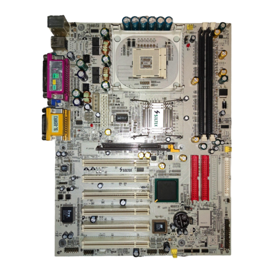
85MR3 / 85MR3-L 1-1 Mainboard Layout LAN Controller for 85MR3-L only Jp10 RJ45 PS/2 Mouse Fan1 (on top) PS/2 K/B (underside) RJ45 (on top) USB0 (middle) LED1 USB1 (underside) i845GE Clock Generator Intel LED2 Jp10 Jp11 AGP 4X RTL8100B PCI 1... -
Page 8: Mainboard Specifications
Chapter 1 Specification 1-2 Mainboard Specifications 1-2.1 CPU Socket ® CPU Socket 478B on board, supporting Intel Pentium 4 processor (including hyper-threading CPUs) in 478-pin package for : -- 533/400MHz System Bus -- Hyper-pipelined technology -- Advanced dynamic execution -- Advanced transfer cache 1-2.2 System Chipsets •... -
Page 9: 1-2.6 2D/3D Vga On Board
85MR3 / 85MR3-L 1-2.6 2D/3D VGA on board • Built-in VGA Graphics Controller in i845GE, supporting one 15-pin connector on board for CRT 2D, 3D VGA display • VGA/AGP display safeguarded by jumper setting (see Jumper Set- ting section for VGA/AGP select •... -
Page 10: 1-2.10 Lan On Board (For 85Mr3-L Only)
Chapter 1 Specification 1-2.10 LAN on board (for 85MR3-L only) PCI local bus single-chip Fast Ethernet Controller RTL8100B on board: • Supporting 10/100Mb data transfer • Supporting Wake On LAN function through the on-board RJ45 LAN Connector • LAN Driver enclosed in Support CD for user’s installation. -
Page 11: Mainboard Specification Table
85MR3 / 85MR3-L 1-3 Mainboard Specification Table 85MR3 / 85MR3-L Specifications and Features Socket 478B for Intel Pentium 4 CPU North Bridge Intel 845GE, supporting 533/400MHz FSB South Bridge Intel ICH4 BIOS AMI BIOS Memory Supporting DDR 333/266 DRAM, up to 2GB... -
Page 12: Chipset System Block Diagram
Chapter 1 Specification 1-4 Chipset System Block Diagram Intel Pentium 4 CPU System Bus 533/400MHz Interface DDR memory Connector Interface System Intel 845GE Memory DDR 333/ North Bridge AGP 4X 266 DRAM AGP Slot Bi-directional 16-bit Data Bus, 266MHz 6 PCI Slots PCI Bus Audio Codec AC’97 2.2... -
Page 13: Chapter 2 Hardware Setup
85MR3 / 85MR3-L Chapter 2 Hardware Setup To Get Things Ready for Hardware Setup ! 1. We recommend to install your CPU before any other components. For detailed installation instructions of processor, you can also refer to the pamphlet enclosed in your CPU package. -
Page 14: Cpu Identification And Installation
Chapter 2 Hardware Setup 2-1 CPU Identification and Installation 2-1.1 To Identify a Pentium 4 CPU Intel pentium 4 2.4 GHz / 512 / 533 / 1.5V (Including hyper-threading CPU) 4. CPU Voltage Vcore 3. System Clock 2. CPU L2 Cache 1. -
Page 15: 2-1.2 Cpu Installation With Socket 478B
85MR3 / 85MR3-L 2-1.2 CPU Installation with Socket 478B This mainboard is built with CPU Socket 478B ( 478-pin) supporting the Intel Pentium 4 CPU: • Follow the steps described in this section to install the 478-pin Pen- tium 4 CPU into the on board Socket 478. -
Page 16: Pentium 4 Cpu Fan Installation
Chapter 2 Hardware Setup 2-2 Pentium 4 CPU Fan Installation CPU Fan Connector Pentium 4 Fanbase Press down the spring locks to lock up the fan Connect to CPU FAN connector... -
Page 17: Memory Installation
85MR3 / 85MR3-L 2-3 Memory Installation How to tackle the memory Modules: • Make sure to unplug your power supply before adding or removing memory module. Failure to do so may cause severe damage to both your mainboard and the memory module. -
Page 18: 2-3.2 Indicator Led1: Dimm Powered On
Chapter 2 Hardware Setup 2-3.2 Indicator LED1: DIMM Powered On An indicator LED 1 is designed on board. Whenever system is started, all the DIMM slots on board will also get powered on, resulting in LED 1 lighting up. This indicator is to warn users that, whenever DIMM slot is powered, no memory module should be removed from or added onto it. -
Page 19: Install Vga / Agp4X With Led2 & Jp11 Safeguard
85MR3 / 85MR3-L 2-4 Install VGA / AGP4X with LED2 & Jp11 Safeguard 1. To install on-board VGA, please connect your monitor directly to VGA connector on board. Default Jp11 2-3 closed is to assure booting system with on-board VGA or 1.5V AGP4X add-on card yet without safeguard against 3.3V AGP2X card. -
Page 20: Ide Connector Installation
Chapter 2 Hardware Setup 2-5 IDE Connector Installation To install IDE Connector, you may connect the blue connector of IDE cable to the primary (IDE1) or secondary (IDE2) connector on board, and then connect the gray connector to your slave device and the black connector to your master device. -
Page 21: Floppy Drive Connector ( Fdc ) Installation
85MR3 / 85MR3-L 2-6 Floppy Drive Connector ( FDC ) Installation To install FDC, you should connect the end of FDC cable with single connector to the board , and connect the other end with two connectors to the floppy drives. -
Page 22: Atx V2.03 Power Supply Installation
Chapter 2 Hardware Setup 2-7 ATX V2.03 Power Supply Installation +12V Power Connector +12V PWR_OK +12V +12V PS_ON# PS/2 Mouse (on top) Fan1 PS/2 K/B (underside) -12V +3.3V RJ45 (on top) USB0 (middle) +3.3V +3.3V LED1 USB1 (underside) Pin11 Pin1 Main Power Connector i845GE (20-pin) -
Page 23: Jumper Settings
85MR3 / 85MR3-L 2-8 Jumper Settings The following diagrams show the locations and settings of jumper blocks on the mainboard. PS/2 Mouse Fan1 (on top) PS/2 K/B (underside) RJ45 CPU Clock Select (on top) USB0 (middle) LED1 USB1 (underside) (default) -
Page 24: 2-8.1 Jp4: Cpu Clock Select
Chapter 2 Hardware Setup How to tackle the Jumpers: A 2-pin Jumper A 3-pin Jumper If a pin-header (of 2 or more pins) is designed in such a way that its pins can be closed or linked together to The conductor inside the cap set up a specific function, this header links two header-pins together. -
Page 25: 2-8.2 Jbat1: Clear Cmos
85MR3 / 85MR3-L Further Notes on CPU Overclocking: 1. If you have successfully booted system with or without CPU overclock, you still can do another CPU overclock in BIOS Setup. Please enter BIOS Setup, choose “Frequency/Voltage Control” menu, and take the “Use Linear”... -
Page 26: 2-8.3 Jp1: Kb /Mouse / Power Button Select
2-3 closed To power on by keyboard / Mouse 2-8.4 Jp10: LAN Controller Select (85MR3-L only) JP10 is a 2-pin jumper for enabling or disabling the on-board LAN Controller. Users can set JP10 OPEN to enable the on-board LAN Con- troller so as to set up the LAN driver, or to set it CLOSED to disable the on-board LAN Controller. -
Page 27: 2-8.5 Jp11: Vga/Agp 4X Safeguard
85MR3 / 85MR3-L 2-8.5 Jp11: VGA/AGP 4X Safeguard 1. Default Jp11(2-3 closed) is to disable safeguard against 3.3V AGP2X card and allow booting system with either 1.5V on-board VGA or 1. 5V AGP4X add-on card. User can choose either VGA or AGP 4X as t h e i n i t i a l d i s p l a y b y c h a n g i n g B I O S S e t u p ( s e e “... -
Page 28: Other Connectors Configuration
Chapter 2 Hardware Setup 2-9 Other Connectors Configuration This section lists out all connectors configurations for users’ reference. 2-9.1 On Board FAN Connectors Void PS/2 Mouse Fan1 (on top) +12V PS/2 K/B (underside) RJ45 (on top) +12V USB0 (middle) LED1 USB1 (underside) SENSOR Sensor Conn. -
Page 29: 2-9.2 Usb Ports And Usb Pin-Headers
85MR3 / 85MR3-L 2-9.2 USB Ports and USB Pin-headers This series provides two USB ports USB0 and USB1 on board sup- porting various USB devices. In addition, two USB pin-headers are added on board to provide expansion of four more optional USB ports by using two additional USB cables. -
Page 30: 2-9.3 Chassis Panel Connectors
Chapter 2 Hardware Setup 2-9.3 Chassis Panel Connectors G : COM1 Connector A : PS/2 Mouse H : VGA Connector B : RJ45 (top) (85MR3-L) : Line Out / C : LPT1 Port Front Speaker Out D : GAME/MIDI J : Line in/... -
Page 31: 2-9.5 Cd-Rom Audio Connectors (Cd 1)
85MR3 / 85MR3-L 2-9.5 CD-ROM Audio Connectors (CD 1) CD 1 is an audio connector connecting CD-ROM audio to mainboard. PS/2 Mouse (on top) Fan1 PS/2 K/B (underside) RJ45 (on top) USB0 (middle) LED1 USB1 (underside) CD-ROM Audio Connector i845GE... -
Page 32: 2-9.7 Connector Cn19: Wake On Lan
Chapter 2 Hardware Setup 2-9.7 Connector CN19: Wake On LAN 1. This connector connects to a LAN card with a Ring signal output. The connector powers up the system when it receives a wake-up packet or signal through the LAN card. 2. -
Page 33: 2-9.9 Complex Pin-Header
85MR3 / 85MR3-L 2-9.9 Complex Pin-header This complex Pin-header consists of the following connectors for vari- ous supports. When you have fixed the mainboard to the case, join the connectors of this Complex Pin-header to the case Front Panel. PS/2 Mouse... - Page 34 Chapter 2 Hardware Setup 1. SMI Connector (System Management Interrupt): Connection: Connected to the case-mounted Suspend Switch. Function : Manually placing the DOS system into a Suspend mode or “Green” mode by System Management Interrupt. 2. Power Switch Connector: Connection: Connected to a momentary button or switch. Function : Manually switching the system between “On”...
-
Page 35: 2-9.10 Rt2 And Jp14: Thermal Connectors
85MR3 / 85MR3-L 2-9.10 RT2 and JP14: Thermal Connectors PS/2 Mouse (on top) Fan1 PS/2 K/B (underside) RJ45 (on top) USB0 (middle) LED1 USB1 (underside) RT2 is mounted with Thermal Resistor i845GE by default. Clock Generator Intel LED2 Jp10 Jp11... -
Page 36: Irq Description
Chapter 2 Hardware Setup 2-10 IRQ Description Function Description Priority IRQ 0 System Timer IRQ 1 Keyboard Controller IRQ 2 Programmable Interrupt IRQ 3 Serial Port (COM 2) IRQ 4 Serial Port (COM 1) IRQ 5 Free IRQ 6 Floppy Disk Controller IRQ 7 Parallel Port (LPT1) IRQ 8... -
Page 37: Chapter 4 Ami Bios Setup
85MR3 / 85MR3-L Chapter 4 AMI BIOS Setup THE BIOS BIOS stands for Basic Input and Output System. It was once called ROM BIOS when it was stored in a Read-Only Memory (ROM) chip Now manufacturers would like to store BIOS in EEPROM which means Electrically Erasable Programmable Memory. -
Page 38: About Bios Setup
Chapter 4 BIOS Setup 4-1 About BIOS Setup BIOS setup is an interactive BIOS program that you need to run when: 1. Changing the hardware of your system. (For example: installing a new Hard Disk etc.) 2. Modifying the behavior of your computer. (For example: changing the system time or date, or turning special features on or off etc.) 3. -
Page 39: To Update Bios
85MR3 / 85MR3-L 4-5 To Update BIOS • System BIOS is incorporated into a Flash memory component. Flash BIOS allows user to upgrade BIOS without the need to replace an EPROM component. • The Upgrade Utility can be loaded on a floppy diskette for upgrading saving, and verifying the system BIOS. - Page 40 Chapter 4 BIOS Setup Step 4. Under “ A “ prompt, type “ AMIXXX.EXE *.ROM “ and then press <Enter> to run BIOS update program. Please note that there should be a space between AMIXXX.EXE and *.ROM. (*.ROM depends on your mainboard model and version code. Instead of typing “*”, you should type the specific file name for your specific mainboard).
-
Page 41: Bios Setup
85MR3 / 85MR3-L 4-6 BIOS SETUP --- CMOS Setup Utility 4-6.1 CMOS Setup Utility This mainboard comes with the AMI BIOS from American Megatrends Inc. Enter the CMOS Setup Utility Main Menu by: 1. Turn on or reboot your system. After a series of diagnostic checks, the following message will appear: PRESS <Del>... -
Page 42: 4-6.2 Standard Cmos Setup
Chapter 4 BIOS Setup 4-6.2 Standard CMOS Setup Standard CMOS Setup records some basic system hardware configuration and sets the system clock and error handling. Modify the configuration values of this option if you want to change your system hardware configuration or after you clear CMOS data. Run the Standard CMOS Setup as follows: 1. - Page 43 85MR3 / 85MR3-L System Time The BIOS shows the time of the day in the format: hh:mm:ss. Choose the field with the Arrow keys and change the time with the Page Up/Page Down +/- keys. System Date The BIOS shows the date of the day in the format: mm:dd:yy :day of the Week.
- Page 44 Chapter 4 BIOS Setup Type This option shows the types of configuration for the IDE devices: 1-50: Predefined types USER: set Parameters by User Auto: Set parameters automatically CD-ROM: Use for ATAPI CD-ROM drives Double click [Auto] to set all HDD parameters automatically, including “Cylinders, Heads, Write Precompensation, Sectors, Maximum Capacity and 32 Bit Transfer Mode.
-
Page 45: 4-6.3 Advanced Bios Features
85MR3 / 85MR3-L 4-6.3 Advanced BIOS Features Advanced BIOS Features improves your system performance or sets up system features according to your preference. Run the Advanced BIOS Features as follows: 1. Choose “Advanced BIOS Features” from the Main Menu and a screen with a list of options will appear: AMIBIOS NEW SETUP UTILITY - VERSION 3.31a... - Page 46 Chapter 4 BIOS Setup 2. Use one of the arrow keys to move between options and modify the selected options by using PgUp / PgDn / + / - keys. An explanation of the <F> keys follows: <F1>: “Help” gives options available for each item. <F9>: Setup BIOS default values.
- Page 47 85MR3 / 85MR3-L Floppy Drive Seek Disabled (default), Floppy Drives will not be checked and diagnosed at system bootup; Enabled, Floppy Drives will be checked and diagnosed at system bootup. PS/2 Mouse Support Enabled (default), PS/2 mouse is supported. Disabled, PS/2 Mouse is not supported Primary Display Allows you to choose the primary display for the system.
-
Page 48: 4-6.4 Advanced Chipset Features
Chapter 4 BIOS Setup 4-6.4 Advanced Chipset Features Advanced Chipset Features is used to modify the values of chipset buffers. These buffers control the system options. Run the Advanced Chipset Features as follows: 1. Choose “Advanced Chipset Features” from the Main Menu and a list of option will appear: AMIBIOS NEW SETUP UTILITY - VERSION 3.31a Advanced Chipset Features... - Page 49 85MR3 / 85MR3-L (Hyper-threading If hyper-threading CPU is running on board, this item Function) appears to show the enabled status. Choices: Enabled; Disabled SDRAM Frequency Allows you to set the SDRAM frequency. Choicesfor 100MHz CPU: Auto; 200MHz; 266MHz Choices for 133MHz CPU: Auto; 200MHz;266MHz;...
- Page 50 Chapter 4 BIOS Setup Memory Hole Allows you to enabled / disabled (default) the sup- port of Memory Hole which is reserved for ISA card. APIC Interrupt Mode Allows you to enable / disable (default) the APIC function for selecting the APIC interrupt Mode. Internal Graphic Mode Allows you to set the internal graphic mode.
-
Page 51: 4-6.5 Power Management Features
85MR3 / 85MR3-L 4-6.5 Power Management Features Power Management Features allows you to set the system’s power saving functions. Run the Power Management Features as follows: 1. Choose “Power Management Features” from the Main Menu and a list of options will appear: AMIBIOS NEW SETUP UTILITY - VERSION 3.31a... - Page 52 Chapter 4 BIOS Setup ACPI Standby State This item allows you to select the ACPI Suspend type. You can select S3(STR) for suspending to DRAM if your system supports this mode. Or you can select S1 (POS) for Power on Suspend under ACPI mode.
- Page 53 85MR3 / 85MR3-L Resume on PME# Allows you to enable / disable the Resume on PME function. Resume On RTC Alarm Allows you to enable / disable the Resume On RTC Alarm function. RTC Alarm Date / Hour If resume On RTC Alarm is enabled, this field al-...
-
Page 54: 4-6.6 Pnp / Pci Configurations
Chapter 4 BIOS Setup 4-6.6 PNP / PCI Configurations PNP/PCI Configuration allows you to modify the system’s power saving functions. Run the PNP/PCI Configurations as follows: 1. Choose “PNP/PCI Configurations” from the Main Menu and a screen with a list of options will appear: AMIBIOS NEW SETUP UTILITY - VERSION 3.31a PNP/PCI Configurations Setup Help... - Page 55 85MR3 / 85MR3-L Clear NVRAM Allows BIOS to clear the NVRAM data. Choices: No (default); Yes PCI Latency Timer (PCI Allows you to set the PCI Latency Time. Clocks) Choices: 32; 64; 96; 192; 128; 160; 192; 224; 248; Init. Graphics Adapter Allows you to select the initial Graphics Adapter.
-
Page 56: 4-6.7 Integrated Peripherals
Chapter 4 BIOS Setup 4-6.7 Integrated Peripherals Integrated Peripherals option allows you to get some information inside your system when it is working. Run the Integrated Peripherals as follows: 1. Choose “Integrated Peripherals” from the Main Menu and a list of options will appear: AMIBIOS NEW SETUP UTILITY - VERSION 3.31a Integrated Peripherals... - Page 57 85MR3 / 85MR3-L Onboard IDE Allows you to choose the Onboard IDE Mode. Choices: Disabled; Primary; Secondary; Both If this option is on board, this item allows you to en- (Optional) Onboard able / disable the onboard LAN. Choices: Enabled; Disabled Onboard AC‘97 Audio Allows you to disable AC’...
- Page 58 Chapter 4 BIOS Setup OnBoard MIDI Port Allows you to configure onboard MIDI port address. The choices: Disabled; 300h; 330h MIDI Port IRQ If the onboard MIDI port is set at 300h or 330h, this item shows up to allow you to configure the MIDI Port IRQ to IRQ 5.
-
Page 59: 4-6.8 Hardware Monitor Status
85MR3 / 85MR3-L 4-6.8 Hardware Monitor Status This menu helps you to read only and get more information on the working CPU temperature, FAN speed and voltage. 1. Choose “Hardware Monitor Status” from the Main Menu and a screen with a list of current status of your working system will appear: AMIBIOS EASY SETUP UTILITY - VERSION 3.31a... - Page 60 Chapter 4 BIOS Setup Temperature 1 Shows current CPU internal temperature. Temperature 2 Shows current CPU external temperature. Temperature 3 Shows current system temperature. Fan 1 / 2 /3 Displays the current speed of CPU Fan, and other two onboard devices which user has connected to the onboard Fan Connectors.
-
Page 61: 4-6.9 Frequency/Voltage Control
85MR3 / 85MR3-L 4-6.9 Frequency/Voltage Control Run the “Frequency/Voltage Control” as following: 1. Choose “Frequency/Voltage Control” from the Main Menu and a screen with a list of options will appear: AMIBIOS EASY SETUP UTILITY - VERSION 3.31a Frequency/Voltage Control Setup Help... - Page 62 Chapter 4 BIOS Setup (Optional) Redstorm Press <Enter> to start RED STORM OVERCLOCK- Overclocking Tech ING TECH. This option gives user an easy way to overclocking. It will increase CPU external clock automatically. When CPU external clock increases to an unacceptably high value, BIOS will restart your system, then running at an acceptable CPU exter- nal clock.
-
Page 63: 4-6.10 Set Supervisor Password
85MR3 / 85MR3-L 4-6.10 Set Supervisor Password This option allows you to set a Supervisor password for the system: 1. Choose “Set Supervisor Password” in the Main Menu and press <Enter>. Then the following message appears: [ Enter new supervisor password ] 2. - Page 64 Chapter 4 BIOS Setup 8. To change or remove a current supervisor password, choose “Set Supervisor Password” and press <Enter>. An instruction box appears on the screen, prompting you to enter the current password first: [ Enter current supervisor password ] 9.
- Page 65 85MR3 / 85MR3-L 4-6.11 Load Optimized Defaults When you press <Enter> on this item, you will get a confirmation dialog box with a message similar to: [ Load Optimized Defaults ] Press [Enter] to continue or [ESC] to abort Press <Enter> now to load Optimal values for all the Setup options.
Need help?
Do you have a question about the 85MR3 and is the answer not in the manual?
Questions and answers