Table of Contents
Advertisement
Quick Links
85SD-C
Chapter 1 Specification ............................................................ 8
1-1 Mainboard Specifications ...........................................................9
1-1.1 CPU Socket .................................................................................... 9
1-1.2 Sysem Chipset Architecture ........................................................... 9
1-1.3 Memory .......................................................................................... 9
1-1.4 AMI BIOS ...................................................................................... 9
1-1.5 Hardware Monitor .......................................................................... 9
1-1.6 Sound Controller .......................................................................... 10
1-1.7 Multi-I/O Function ....................................................................... 10
1-1.8 Expansion Slots ............................................................................ 10
1-1.9 Accelerated Graphics port (AGP) Interface ................................. 10
1-1.10 FORM FACTOR ........................................................................ 10
1-1.11 Power Management .................................................................... 11
1-2 MainBoard Layout ....................................................................12
1-3 Chipset System Block Diagram ................................................13
Chapter 2 Hardware Setup .................................................... 14
2-1 Pentium 4 CPU Installation with Socket 478 ............................ 15
2-2 Pentium 4 CPU Fan Installation: ..............................................16
2-3 Memory Installation ..................................................................17
2-3.1 To Install DIMM Module ............................................................. 17
2-3.2 To Remove a DIMM: ................................................................... 18
2-3.3 LED1: DIMM Socket Powered On ............................................. 18
2-4 AGP 4X (Accelerated Graphics Port) Installation ..................19
2-5 HDD/FDD Installation .............................................................. 20
2-6 Jumper and Switch Settings ......................................................22
2-6.1 Switch 1 CPU Clock Select ......................................................... 23
2-6.2 Factory Test (By JP13/JP14) ........................................................ 24
CONTENT
4
Advertisement
Table of Contents

Related Manuals for SOLTEK SL-85SD-C


Summary of Contents for SOLTEK SL-85SD-C
-
Page 1: Table Of Contents
85SD-C CONTENT Chapter 1 Specification ............8 1-1 Mainboard Specifications ............9 1-1.1 CPU Socket ..................9 1-1.2 Sysem Chipset Architecture ............9 1-1.3 Memory ..................9 1-1.4 AMI BIOS ..................9 1-1.5 Hardware Monitor ................9 1-1.6 Sound Controller ................10 1-1.7 Multi-I/O Function ............... - Page 2 Content 2-6.3 JBAT1 Clear CMOS ..............24 2-7 Other Connectors Configuration ..........25 2-7.1 On Board FAN Connectors (FAN1,FAN2, FAN3) ...... 25 2-7.2 WOL1 Wake On LAN ..............26 2-7.3 CD-ROM Audio Connector (CD1/CD2) ........27 2-7.4 Thermal Sensor Connector (JP7) (Optional) ........ 28 2-7.5 Complex Header NJ1 ..............
- Page 3 85SD-C 4-6.1 CMOS Setup Utility ..............49 4-6.2 Standard CMOS Setup ..............50 4-6.3 Advanced BIOS Features ............. 53 4-6.4 Advanced Chipset Features ............56 4-6.5 Power Management Setup ............59 4-6.6 PNP / PCI Configuration .............. 61 4-6.7 Integrated Peripherals ..............63 4-6.8 Hardware Monitor Status .............
- Page 4 Chapter 1 Specification ITEM LIST CHECKUP Mainboard Support CD Bundled Bonus Pack CD Bundled Bonus Pack Manual Thermal Cable (optional) ATA66/100 IDE Cable RS232 Cable FDD Cable User’s Manual...
-
Page 5: Chapter 1 Specification
85SD-C Chapter Specification Introduction • This chapter introduces the characteristics of this series of mainboards. It includes the information on the chipset, CPU types, built-in functions and layout. Users will have more ideas about this powerful series after reading this chapter. The topics contained in this chapter are: 1-1 Mainboard Specifications 1-2 Mainboard Layout... -
Page 6: Mainboard Specifications
Chapter 1 Specification 1-1 Mainboard Specifications 1-1.1 CPU Socket • CPU Socket 478B on board, supporting Intel ® Pentium 4 and Northwood processors in the 478-pin package for 400MHz System Bus. 1-1.2 Sysem Chipset Architecture • INTEL 845 Chipset Memory Control Hub (MCH): To work with Intel Pentium 4 Processor for managing and arbitrating between 4 interfaces: -- the System Bus (Host Interface);... -
Page 7: 1-1.6 Sound Controller
85SD-C 1-1.6 Sound Controller • SoundBlaster Pro Hardware and Direct Sound Ready AC97 Digital Audio Controller with Codec onboard. 1-1.7 Multi-I/O Function • Integrated IDE Controller, supporting: -- 2x Ultra ATA100 / 66 / 33 Connectors -- Two UARTs for Complete Serial Ports (2x COM ). •... -
Page 8: 1-1.11 Power Management
Chapter 1 Specification 1-1.11 Power Management • ACPI 1.0B compliant (Advanced Configuration and Power Interface). • APM V1.2 compliant (Legacy power management). • Supporting ACPI suspend POS mode (Power On Suspend). • System event monitoring with two event classes. • Supporting Wake On LAN (WOL) & Wake On Modem. •... -
Page 9: Mainboard Layout
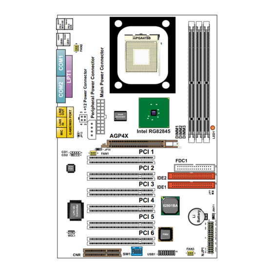
85SD-C 1-2 MainBoard Layout mPGA478B Intel RG82845 Clock Generator Intel RG82845 AGP4X JP14 PCI 1 FAN1 FDC1 PCI 2 AC'97 Codec IDE2 PCI 3 IDE1 PCI 4 82801BA PCI 5 PCI 6 WOL1 FAN3 USB1 1 2 3 4 5... -
Page 10: Chipset System Block Diagram
Chapter 1 Specification 1-3 Chipset System Block Diagram Intel Pentium 4 Processor System Bus (4x100MHz) Bandwidth 3.2GB/s Memory Interface Intel 82845 System AGP 4x Memory (1.5V) PC133 SDRAM AGP Graphics 1.06GB/s -System Bus 1.06GB/s Controller -Memory Controller -AGP Controller -Hub Interface 2 IDE Drives Ultra DMA100/66 PCI Slots... -
Page 11: Chapter 2 Hardware Setup
85SD-C Chapter Hardware Setup To Get things ready for Hardware setup !!! 1. We recommend to install your CPU before any other componentes. For detailed installalation instructions of processor, you can also refer to the pamphlet enclosed in your CPU package. 2. -
Page 12: Pentium 4 Cpu Installation With Socket 478
Chapter 2 Hardware Setup 2-1 Pentium 4 CPU Installation with Socket 478 This series of mainboards are built with CPU Socket 478 (with 478 pins) supporting the Intel Pentium 4 CPU: • Follow the steps described in this section to install the 478-pin Pentium 4 CPU into the on board Socket 478. -
Page 13: Pentium 4 Cpu Fan Installation
85SD-C 2-2 Pentium 4 CPU Fan Installation: Pentium 4 Fan Base Fan Connector Press down 4 latches to lock fan to fan socket Connect to CPU FAN connector... -
Page 14: Memory Installation
Chapter 2 Hardware Setup 2-3 Memory Installation How to tackle the memory Modules: • Make sure to unplug your power supply before adding or removing memory module. Failure to do so may cause severe damage to both your mainboard and the memory module. •... -
Page 15: 2-3.2 To Remove A Dimm
85SD-C 2-3.2 To Remove a DIMM: • Press down the holding latches on both sides of socket and the module will be released from the DIMM socket. 2-3.3 LED1: DIMM Socket Powered On Warning: An indicator LED1 is on board . Whenever system is started, all the DIMM sockets on board will also be powered on with the set voltage, resulting in LED1 lighting up. -
Page 16: Agp 4X (Accelerated Graphics Port) Installation
Chapter 2 Hardware Setup 2-4 AGP 4X (Accelerated Graphics Port) Installation Warning: • The AGP 4X slot on board supports solely 4X AGP card configuration. User should not insert 1X / 2X AGP card to this mainboard. • If an AGP 2X Graphics Card is inserted into this AGP 4X slot, the system will not be started. -
Page 17: Hdd/Fdd Installation
85SD-C 2-5 HDD/FDD Installation • To install HDD (Hard Disk Drive), you may connect the connector of IDE cable to the primary (IDE1) or secondary (IDE2) connector on board, and then connect the gray connector to your slave device and the black connector to your master device. - Page 18 Chapter 2 Hardware Setup • To install FDD (Floppy Disk Drive), you should connect the end of cable with single connector to the board , and connect the other end with two plugs to the floppy drives. mPGA478B Floppy Disk Drive Connector: Orient the red line on the floppy ribbon cable to Pin1.
-
Page 19: Jumper And Switch Settings
85SD-C 2-6 Jumper and Switch Settings • The following diagrams show the locations and settings of jumper blocks on the mainboard. mPGA478B JP13/JP14: Factory Test JP13 Only for factory test. Intel RG82845 Clock Generator JP14 Intel RG82845 AGP4X JP14 PCI 1 FAN1 JBAT1: Clear CMOS Data FDC1... -
Page 20: 2-6.1 Switch 1 Cpu Clock Select
Chapter 2 Hardware Setup How to tackle with Jumpers: • Do not remove the jumper when power is on. Always make sure the power is off before changing any jumper settings. Otherwise, mainboard could be damaged. • In the Jumper setting diagram, all jumper pins covered with black marks stand for closed pins by jumper caps. -
Page 21: 2-6.2 Factory Test (By Jp13/Jp14)
85SD-C 2-6.2 Factory Test (By JP13/JP14) JP13/JP14: Factory Test JP13 Only for factory test. JP14 2-6.3 JBAT1 Clear CMOS • When you have problem with rebooting your system, you can clear CMOS data and restore it to default value. To clear CMOS with Jumper JBAT1, please follow the steps below: (1) Power off system;... -
Page 22: Other Connectors Configuration
Chapter 2 Hardware Setup 2-7 Other Connectors Configuration • This section lists out all connectors configurations for users’ reference. 2-7.1 On Board FAN Connectors (FAN1,FAN2, FAN3) mPGA478B +12V SENSOR Intel RG82845 Clock Generator Intel RG82845 AGP4X JP14 PCI 1 FAN1 FDC1 FAN1, FAN2, FAN3: On-Board FAN Connectors PCI 2... -
Page 23: 2-7.2 Wol1 Wake On Lan
85SD-C 2-7.2 WOL1 Wake On LAN mPGA478B Standby Intel RG82845 Clock Generator Intel RG82845 AGP4X JP14 PCI 1 FAN1 FDC1 PCI 2 AC'97 WOL1: Wake On LAN Codec IDE2 PCI 3 IDE1 Connect the Wake On PCI 4 LAN signal from LAN 82801BA WOL1 card to WOL1... -
Page 24: 2-7.3 Cd-Rom Audio Connector (Cd1/Cd2)
Chapter 2 Hardware Setup 2-7.3 CD-ROM Audio Connector (CD1/CD2) mPGA478B CD1/CD2: CD ROM Audio Connector Intel RG82845 Clock Generator PIN NO. Intel RG82845 AGP4X Left JP14 PCI 1 PIN 1 FAN1 Channel FDC1 PCI 2 Left AC'97 Codec PIN 2 Channel IDE2 PCI 3... -
Page 25: 2-7.4 Thermal Sensor Connector (Jp7) (Optional)
85SD-C 2-7.4 Thermal Sensor Connector (JP7) (Optional) mPGA478B Intel RG82845 Clock Generator Intel RG82845 AGP4X JP14 PCI 1 FAN1 FDC1 PCI 2 AC'97 Codec IDE2 PCI 3 IDE1 PCI 4 82801BA PCI 5 PCI 6 WOL1 FAN3 USB1 1 2 3 4 5 We provide a thermal cable in the mainboard package. -
Page 26: 2-7.5 Complex Header Nj1
Chapter 2 Hardware Setup 2-7.5 Complex Header NJ1 • This complex Header consists of 10 connectors providing various supports: mPGA478B Intel RG82845 Clock Generator Intel RG82845 AGP4X JP14 PCI 1 FAN1 FDC1 PCI 2 AC'97 Codec IDE2 PCI 3 IDE1 PCI 4 82801BA PCI 5... - Page 27 85SD-C 1. SMI Connector (System Management Interrupt): CONNECTION: This 2-pin connector is connected to the case-mounted Suspend Switch. FUNCTION : Manually placing the system into a Suspend mode or “Green” mode. 2. Power Switch Connector: CONNECTION: Connected to a momentary button or switch. FUNCTION : Manually switching the system between “On”...
-
Page 28: 2-7.6 Atx Power Supply Connectors Version 2.03 For Pentium 4
Chapter 2 Hardware Setup 2-7.6 ATX Power Supply Connectors version 2.03 for Pentium 4 • This mainboard is compatible with both ATX Power Supply Version 2.03 (with +12V Power Connector) and the older ATX Power Supply (with Peripheral Power Connector): Important: 1. -
Page 29: 2-7.7 Communication And Networking Riser Slot (Cnr)
85SD-C 2-7.7 Communication And Networking Riser Slot (CNR) • This slot allows you to use network, modem or audio riser cards. mPGA478B Intel RG82845 Clock Generator Intel RG82845 AGP4X JP14 PCI 1 FAN1 FDC1 PCI 2 AC'97 Codec IDE2 PCI 3 IDE1 PCI 4 82801BA... -
Page 30: 2-7.8 Usb Header (Header Usb1)
Chapter 2 Hardware Setup 2-7.8 USB Header (Header USB1) • This header is for providing you two additional USB ports by using an additional USB Cable. User can order the additional USB cable from your mainboard dealers and venders. mPGA478B Additional USB Cable (Optional) Intel RG82845... -
Page 31: 2-7.10 Chassis Panel Connector
85SD-C 2-7.10 Chassis Panel Connector A : PS/2 MOUSE PORT B : USB 0 PORT C : LPT1 PORT D : GAME/MIDI PORT E : PS/2 KEYBOARD PORT F : USB 1 PORT G : COM1 PORT H : COM2 PORT : LINE/SPEAKER OUT J : LINE IN K : MICROPHONE INPUT... -
Page 32: Irq Description
Chapter 2 Hardware Setup 2-8 IRQ Description Function Description Priority IRQ 0 System Timer IRQ 1 Keyboard Controller IRQ 2 Programmable Interrupt IRQ 3 Serial Port (COM 2) IRQ 4 Serial Port (COM 1) IRQ 5 Free IRQ 6 Floppy Disk Controller IRQ 7 Parallel Port (LPT1) IRQ 8... -
Page 33: Chapter 3 Software Setup
85SD-C C hapter Software Setup Drivers, Utilities and Software Installation • Support CD: This series of mainboards will always be shipped with a Support CD which contains those necessary driver files, Application Softwares and some helpful utilities. It is a user-friendly, auto-run CD which will open itself up in a CD-ROM automatically. -
Page 34: Open Up The Support Cd And Choose Drivers And Utilities
Chapter 3 Software Setup 3-1 Open up the Support CD and choose Drivers and Utilities Please put the Support CD enclosed in your mainboard package into the CD-ROM drive. In a few seconds, the Main Menu will automatically appear, displaying the contents to be installed for this series: Intel Chipset Software Installation Utility (INF Utility) Intel Application Accelerator (IAA) -
Page 35: Install "Intel Chipset Software Installation Utility
85SD-C 3-2 Install “Intel Chipset Software Installation Utility” Following the procedures of opening the Support CD, click to “ Install Intel Chipset software installation Utility” to proceed. The Intel Service Pack InstallShield Wizard will pop up to guide you to the I n t e l S e r v i c e p a c k installation. -
Page 36: Install "Intel Application Accelerator
Chapter 3 Software Setup 3-3 Install “Intel Application Accelerator” IAA supports all Windows 98/98se/Mellennium/NT4/2000/XP with Pentium III / 4 processor. Installations of this software for these operating systems are similarly programed to an auto-run mode, and it is typically designed to improve performance of the storage sub- system and overall system performance. - Page 37 85SD-C 4 On ”Choose Destination L o c a t i o n ” screen, press “Yes” to continue. C:\Program Files\Intel\Intel Application Accelerator On ”InstallShield Wizard Com-plete” screen, choose “Yes, I want to restart my Yes, I want to restart my computer now computer now”...
-
Page 38: Ac'97 Audio Driver Installation
Chapter 3 Software Setup 3-4 AC’97 Audio Driver Installation AC’97 Codec is integrated in Chip ALC201A. You can install “ AC’97 Audio Driver” on this mainboard. Following the procedures of opening the Support CD, click to “ AC’97 Audio Driver” to proceed. Instantly, the “InstallShield Wizard”... -
Page 39: Install Hardware Monitor Utility
85SD-C 3-5 Install Hardware Monitor Utility 3-5.1 Installation Hardware Monitor is built on this mainboard. Its installation is programed to a fully automated mode on Windows 9X/Me/NT4/2000/ XP. User can follow the model installation below for its installation on various Windows System. Following the procedures of opening the Support CD, click to “... -
Page 40: 3-5.2 Verification
Chapter 3 Software Setup 3-5.2 Verification A f t e r r e s t a r t i n g y o u r computer, click “Start” and choose the path Programs \Winbond\Hwdoctor to open the main window of the Hard- ware Doctor. - Page 41 85SD-C MEMO MEMO...
-
Page 42: Chapter 4 Ami Bios Setup
Chapter 4 AMI BIOS Setup Chapter 4 AMI BIOS Setup THE BIOS BIOS stands for Basic Input and Output System. It was once called ROM BIOS when it was stored in a Read-Only Memory (ROM) chip Now manufacturers would like to store BIOS in EEPROM which means Electrically Erasable Programmable Memory. -
Page 43: About Bios Setup
85SD-C 4-1 About BIOS Setup BIOS setup is an interactive BIOS program that you need to run when: 1. Changing the hardware of your system. (For example: installing a new Hard Disk etc.) 2. Modifying the behavior of your computer. (For example: changing the system time or date, or turning special features on or off etc.) 3. -
Page 44: To Update Bios
Chapter 4 AMI BIOS Setup 4-5 To Update BIOS • System BIOS is incorporated into a Flash memory component. Flash BIOS allows user to upgrade BIOS without the need to replace an EPROM component. • The Upgrade Utility can be loaded on a floppy diskette for upgrading saving, and verifying the system BIOS. - Page 45 85SD-C Step 4. Under “ A “ prompt, type “ AMIXXX.EXE *.ROM “ and then press <Enter> to run BIOS update program. Please note that there should be a space between AMIXXX.EXE and *.ROM. (*.ROM depends on your mainboard model and version code. Instead of typing “*”, you should type the specific file name for your specific mainboard).
-
Page 46: Bios Setup
Chapter 4 AMI BIOS Setup 4-6 BIOS SETUP --- CMOS Setup Utility 4-6.1 CMOS Setup Utility This mainboard comes with the AMI BIOS from American Megatrends Inc. Enter the CMOS Setup Utility Main Menu by: 1. Turn on or reboot your system. After a series of diagnostic checks, the following message will appear: PRESS <Del>... -
Page 47: 4-6.2 Standard Cmos Setup
85SD-C 4-6.2 Standard CMOS Setup Standard CMOS Setup records some basic system hardware configuration and sets the system clock and error handling. You only need to modify the configuration values of this option if you want to change your system hardware configuration or when the data stored in the CMOS memory gets lost or damaged. - Page 48 Chapter 4 AMI BIOS Setup System Time The BIOS shows the time of the day in the format: hh:mm:ss. Choose the field with the Arrow keys and change the time with the Page Up/Page Down keys. System Date The BIOS shows the date of the day in the format: mm:dd:yy :day of the Week.
- Page 49 85SD-C Type This option shows the types of configuration for the IDE devices: 1-50: Predefined types USER: set Parameters by User Auto: Set parameters automatically CD-ROM: Use for ATAPI CD-ROM drives Double click [Auto] to set all HDD parameters automatically, including “Cylinders, Heads, Write Precompensation, Sectors, Maximum Capacity and 32 Bit Transfer Mode.
-
Page 50: 4-6.3 Advanced Bios Features
Chapter 4 AMI BIOS Setup 4-6.3 Advanced BIOS Features Advanced BIOS Features improves your system performance or sets up system features according to your preference. Run the Advanced BIOS Features as follows: 1. Choose “Advanced BIOS Features” from the Main Menu and a screen with a list of options will appear: AMIBIOS EASY SETUP UTILITY - VERSION 2.01a Setup Help... - Page 51 Choises: Yes; No Initial Display Mode If option is “Silent”, the initial display mode will be set to one with Soltek logo. If option is “BIOS”, the normal BIOS display mode will be shown. Choices: silent (default); BIOS If the item “Initial Display Mode”...
- Page 52 Chapter 4 AMI BIOS Setup BootUp Num-Lock Allows you to Toggle between On or Off to control the state of the NumLock key when the system boots. If On, the numeric keypad is in numeric mode. If off, the numeric keypad is in cursor con- trol mode.
-
Page 53: 4-6.4 Advanced Chipset Features
85SD-C 4-6.4 Advanced Chipset Features Advanced Chipset Features is used to modify the values of chipset buffers. These buffers control the system options. Run the Advanced Chipset Features as follows: 1. Choose “Advanced Chipset Features” from the Main Menu and a list of option will appear: AMIBIOS EASY SETUP UTILITY - VERSION 2.01a Advanced Chipset Features... - Page 54 Chapter 4 AMI BIOS Setup SDRAM Frequency Allows you to set the SDRAM frequency. Choices: Auto; 200MHz; 266MHz Configure SDRAM SPD (Serial presence detect) is a device in memory Timing by SPD module for storing the module information such as DRAM timing and chip parameters.
- Page 55 85SD-C AGP Aperture Size Allows you to set the AGP Aperture Size. Choices: 4MB; 8MB; 16MB; 32MB; 64MB; 128MB; 256MB; USB Controller Allows you to set the USB Controller on the USB port(s). Choices: All USB; USB Port 0&1; USB Port 2&3; disabled USB 1.1 Device Legacy Allows you to select the USB Device Legacy support.
-
Page 56: 4-6.5 Power Management Setup
Chapter 4 AMI BIOS Setup 4-6.5 Power Management Setup Power Management Setup allows you to set the system’s power saving functions. Run the Power Management Setup as follows: 1. Choose “Power Management Setup” from the Main Menu and a list of options will appear: AMIBIOS EASY SETUP UTILITY - VERSION 2.01a Power Management Features... - Page 57 85SD-C ACPI Standby State This item allows you to select the ACPI Suspend type. You can select S3(Suspend to RAM STR) for suspending to DRAM if your system supports this mode. Or you can select S1 (POS) for Power on Suspend under Windows 98 ACPI mode..
-
Page 58: 4-6.6 Pnp / Pci Configuration
Chapter 4 AMI BIOS Setup 4-6.6 PNP / PCI Configuration PNP/PCI Configuration allows you to modify the system’s power saving functions. Run the PNP/PCI Configuration as follows: 1. Choose “PNP/PCI Configuration” from the Main Menu and a screen with a list of options will appear: AMIBIOS EASY SETUP UTILITY - VERSION 2.01a PNP/PCI Configurations Setup Help... - Page 59 85SD-C Plug & Play Aware O/S Select Yes for Windows systems supporting Plug and Play function. Select No for systems not sup- porting PNP. PCI Latency Timer (PCI Allows you to set the PCI Latency Time. Clocks) Choices: 32; 64; 96; 192; 128; 160; 192; 224; 248; Primary Graphics Allows you to set the Primary Graphics Adaptor.
-
Page 60: 4-6.7 Integrated Peripherals
Chapter 4 AMI BIOS Setup 4-6.7 Integrated Peripherals Integrated Peripherals option allows you to get some information inside your system when it is working. Run the Integrated Peripherals as follows: 1. Choose “Integrated peripherals” from the Main Menu and a list of options will appear: AMIBIOS EASY SETUP UTILITY - VERSION 2.01a Integrated Peripherals... - Page 61 85SD-C Onboard IDE Allows you to choose the Onboard IDE Mode. Choices: Disabled; Primary; Secondary; Both OnBoard AC’97 Audio Allows you to enable / disable onboard AC’97 Audio. Choices: Auto; Disabled Allows you to enable / disable the Onboard MC’97 Onboard MC’97 Modem.
- Page 62 Chapter 4 AMI BIOS Setup OnBoard MIDI Port Allows you to configure onboard MIDI port address. The choices: Disabled; 300h; 330h MIDI IRQ Select If the onboard MIDI port is set at 300h or 330h, this item shows up to allow you to configure the MIDI Port IRQ to IRQ 5.
-
Page 63: 4-6.8 Hardware Monitor Status
85SD-C 4-6.8 Hardware Monitor Status This menu helps you to read only and get more information on the working CPU temperature, FAN speed and voltage. 1. Choose “Hardware Monitor Status” from the Main Menu and a screen with a list of current status of your working system will appear: AMIBIOS EASY SETUP UTILITY - VERSION 2.01a Hardware Monitor Status Setup Help... - Page 64 Chapter 4 AMI BIOS Setup CPU1Temperature Shows current temperature of the CPU body. CPU 2 Temperature Shows current temperature round the CPU. System Temperature Shows current system temperature. CPU Fan Speed Displays the current speed of CPU Fan. Case Fan Speed Shows current Case Fan Speed. Power Fan Speed Shows current Power Fan Speed.
-
Page 65: 4-6.9 Frequency/Voltage Control
85SD-C 4-6.9 Frequency/Voltage Control Run the “Frequency/Voltage Control” as following: 1. Choose “Frequency/Voltage Control” from the Main Menu and a screen with a list of options will appear: AMIBIOS EASY SETUP UTILITY - VERSION 2.01a Frequency/Voltage Control Setup Help Redstorm Overclocking Tech (optional) Press Enter CPU Linear Freq Disabled... - Page 66 Chapter 4 AMI BIOS Setup (Optional) Redstorm Press <Enter> to start RED STORM OVERCLOCK- Overclocking Tech ING TECH. This option gives user an easy way to overclocking. It will increase CPU external clock automatically. When CPU external clock increases to an unacceptable value, BIOS will restart your system, then running at an acceptable CPU exter- nal clock.
-
Page 67: 4-6.10 Set Supervisor Password
85SD-C 4-6.10 Set Supervisor Password This option allows you to set a Supervisor password for the system: 1. Choose “Set Supervisor Password” in the Main Menu and press <Enter>. Then the following message appears: [ Enter new supervisor password ] 2. - Page 68 Chapter 4 AMI BIOS Setup 8. To change or remove a current supervisor password, choose “Set Supervisor Password” and press <Enter>. An instruction box appears on the screen, prompting you to enter the current password first: [ Enter current supervisor password ] 9.
-
Page 69: 4-6.11 Load Optimized Defaults
85SD-C 4-6.11 Load Optimized Defaults When you press <Enter> on this item, you will get a confirmation dialog box with a message similar to: [ Load Optimized Defaults ] Press [Enter] to continue or [ESC] to abort Press <Enter> now to load Optimal values for all the Setup options. 4-6.12 Save &...
Need help?
Do you have a question about the SL-85SD-C and is the answer not in the manual?
Questions and answers