
Related Manuals for SOLTEK SL-85DIV


Summary of Contents for SOLTEK SL-85DIV
- Page 1 T h e S o u l C o m p u t e r T e c h n o l o g y Mainboard SL-85DIV / 85DIV-L User Manual V1.2...
- Page 2 Soltek Computer Inc. has been advised of the possibility of such damages arising from any defect or error in this manual or product.
- Page 3 85DIV / 85DIV-L SOLTEK AROUND THE WORLD SOLTEK COMPUTER INC. Address : 7F, No. 306-3, Ta-Tung Rd, Sec.1, Hsi-Chih, Taipei- Hsien, Taiwan, R.O.C. Telephone : 886-2-2642-9060 : 886-2-2642-9065 E-mail : sales@soltek.com.tw Web site : http://www.soltek.com.tw SOUL TECHNOLOGY EUROPE B.V. Address : Hongkongstraat 55, 3047 BP Rotterdam.
-
Page 4: Table Of Contents
Contents Contents Chapter 1 Specification ........... 10 1-1 Mainboard Specifications ............. 11 1-1.1 CPU Socket ................... 11 1-1.2 System Chipsets ................11 1-1.3 Memory ..................11 1-1.4 AWARD BIOS V6.0 ..............11 1-1.5 Accelerated Graphics Port (AGP) Interface ......11 1-1.6 Advanced system Power Management, supporting: .... - Page 5 Contents 2-7.1 Switch 1 System Clock Adjust ........... 26 2-7.2 JBAT1 Clear CMOS ..............27 2-7.3 Jp7 Built-in LAN Select (for 85DIV-L only) ......27 2-7.4 Jp6 CPU Clock Select: ..............28 2-8 Other Connectors Configuration ........29 2-8.1 On Board FAN Connectors ............29 2-8.2 CD-ROM Audio Connector CD_IN1 ........
- Page 6 Contents 4-5 To Upgrade BIOS ..............52 4-5.1 Before Upgrading BIOS ............. 52 4-5.2 Upgrade Process ................52 4-6 BIOS SETUP --- CMOS Setup Utility ........ 55 4-6.1 CMOS Setup Utility ..............55 4-6.2 Standard CMOS Setup ............... 56 4-6.3 Advanced BIOS Features ............59 4-6.4 Advanced Chipset Features ............
- Page 7 Contents...
- Page 8 85DIV / 85DIV-L ITEM CHECKUP Mainboard Support CD Bundled Bonus Pack CD Bundled Bonus Pack Manual Temperature Sensor Cable (Optional) ATA66/100/133 IDE Cable FDD Cable User’s Manual RS232 Cable...
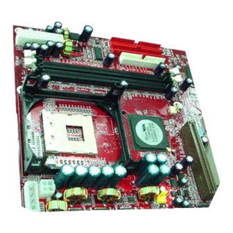
- Page 9 Chapter 1 Specification 85DIV / 85DIV-L -- Component Locations for 85DIV-L only Peripheral PS/2 (on top) Power Mouse (underside) PS/2 K/B Rj45 (on top) +12V Power mPGA478B USB0 (middle) (underside) USB1 Main Power FAN 1 P4X266A FAN 2 FAN3 AGP 4X / 2X RTL8139C PCI 1 1 2 3 4...
-
Page 10: Chapter 1 Specification
85DIV / 85DIV-L Chapter 1 Specification Introduction This mainboard features an integration of the powerful processor In- tel Pentium 4 and the single-chip North Bridge VIA P4X266A plus South Bridge VT8233A, by which the whole system performance is upgraded to 533/400 MHz system bus. The Intel P4 processor is a rapid execution engine providing 400MHz quadpumped system bus to allow 3.2GB data transfer rates possible, while VIA Apollo P4X266A North Bridge plus VT8233A South Bridge... -
Page 11: Mainboard Specifications
Chapter 1 Specification 1-1 Mainboard Specifications 1-1.1 CPU Socket ® CPU Socket 478B on board, supporting Intel Pentium 4 and North- wood processors in the 478-pin package for : • 533/400 MHz System Bus; • Hyper pipelined technology; • Advanced dynamic execution; •... -
Page 12: 1-1.6 Advanced System Power Management, Supporting
85DIV / 85DIV-L 1-1.6 Advanced system Power Management, supporting: • ACPI 1.0B compliant (Advanced Configuration and Power Interface); • APM V1.2 compliant (Legacy power management); • POS (Power On Suspend); • Wake On Modem (External) and Wake On LAN supported by Ring Power On Control;... -
Page 13: 1-1.9 Hardware Monitor On Board
Chapter 1 Specification 1-1.9 Hardware Monitor on board Programmable hardware status, to provide monitoring and alarm for flexible desktop management of hardware temperatures. Utility Soft- ware is enclosed in Support CD to help display monitoring statuses of: -- 8 voltages, 3 types of hardware temperatures, 2 Fan speeds; 1-1.10 AC’97 Audio Codec on board AC’97 Audio Codec supported by AC’97 Link on chip VT8233A;... -
Page 14: Mainboard Specification Table
85DIV / 85DIV-L 1-2 Mainboard Specification Table 85DIV / 85DIV-L Model/Series Memory North Bridge VIA P4x266 A Controller Hub South Bridge VIA VT8233A Controller Hub CPU Socket Socket PGA478B for Intel Pentium 4 478-pin package CPU Supporting 2GB unbuffered Memory DDR SDRAMs with 2 DDR DIMM Slots I/O Chip ITE IT8705F... -
Page 15: Chipset System Block Diagram
Chapter 1 Specification 1-3 Chipset System Block Diagram Intel Pentium 4 478-pin package 533/400 MHz FSB P4x266A PC2100/1600 DDR Memory Bus AGP 2X/4X Bus Single-chip Slot North Bridge SDRAMs 66MHz QDR, 8Bit V-Link (For 85DIV-L only) BIOS LAN Connector Rtl8139C PCI Slots PCI Bus Modem Codec... - Page 16 85DIV / 85DIV-L MEMO MEMO...
-
Page 17: Chapter 2 Hardware Setup
Chapter 2 Hardware Setup Chapter 2 Hardware Setup To Get things ready for Hardware setup ! 1. We recommend to install your CPU before any other components. For detailed installation instructions of processor, you can also refer to the pamphlet enclosed in your CPU package. 2. -
Page 18: Cpu Installation With Socket 478
85DIV / 85DIV-L 2-1 CPU Installation with Socket 478 This mainboard is built with CPU Socket 478 ( 47-pin) supporting the Intel Pentium 4 CPU: • Follow the steps described in this section to install the 478-pin Pen- tium 4 CPU into the on board Socket 478. •... -
Page 19: Pentium 4 Cpu Fan Installation
Chapter 2 Hardware Setup 2-2 Pentium 4 CPU Fan Installation: Pentium 4 Fanbase CPU Fan Connector Press down 4 corners to lock fan to fanbase Connect Fan Connector to CPU FAN connector... -
Page 20: Memory Installation
85DIV / 85DIV-L 2-3 Memory Installation How to tackle with the memory Modules: • Make sure to unplug your power supply before adding or removing memory module. Failure to do so may cause severe damage to both your main board and the memory module. •... -
Page 21: Agp (Accelerated Graphics Port) Configuration
Chapter 2 Hardware Setup 2-4 AGP (Accelerated Graphics Port) Configuration : The AGP 4X/2X slot on board supports 4X / 2X AGP card configuration. User can install either a 4X or 2X AGP card with its own card driver. AGP Accelerator AGP 4X / 2X Peripheral PS/2... -
Page 22: Hdd/Fdd Installation
85DIV / 85DIV-L 2-5 HDD/FDD Installation To install HDD (Hard Disk Drive), you may connect the connector of IDE cable to the primary (IDE1) or secondary (IDE2) connector on board, and then connect the gray connector to your slave device and the black connector to your master device. - Page 23 Chapter 2 Hardware Setup To install FDD (Floppy Disk Drive), you should connect the end of cable with single connector to the board , and connect the other end with two plugs to the floppy drives. (on top) Mouse Floppy Disk Drive Connector: (underside) PS/2 K/B Orient the red line on the...
-
Page 24: Atx V 2.03 Power Supply Installation
85DIV / 85DIV-L 2-6 ATX V 2.03 Power Supply Installation Peripheral PS/2 (on top) Power Mouse (underside) PS/2 K/B Rj45 (on top) +12V Power mPGA478B USB0 Main Power (middle) (underside) USB1 Main Power Connector PIN1 Pin11 +12V FAN 1 PWR_OK P4X266A FAN 2 FAN3... -
Page 25: Jumper And Switch Settings
Chapter 2 Hardware Setup 2-7 Jumper and Switch Settings The following diagrams show the locations and settings of jumper blocks on the mainboard. System Clock Adjust 1234 (Default) Off On On On CPU clock (MHz) (default) (For 85DIV-L only) Peripheral PS/2 (on top) Power... -
Page 26: 2-7.1 Switch 1 System Clock Adjust
85DIV / 85DIV-L How to tackle with Jumpers: • Do not remove the jumper when power is on. Always make sure the power is off before changing any jumper settings. Otherwise, mainboard could be damaged. • In the Jumper setting diagram, all jumper pins covered with black marks stand for closed pins by jumper caps. -
Page 27: 2-7.2 Jbat1 Clear Cmos
Chapter 2 Hardware Setup 2-7.2 JBAT1 Clear CMOS When you have problem with rebooting your system, you can clear CMOS data and restore it to default value. To clear CMOS with Jumper JBAT1, please follow the steps below: 1. Power off system; 2. -
Page 28: 2-7.4 Jp6 Cpu Clock Select
85DIV / 85DIV-L 2-7.4 Jp6 CPU Clock Select: • Jp6 is designed on board for user to select the CPU clock before booting. This mainboard supports CPU that can autodetect CPU clock itself. If you leave Jp6 at default value 1-2 closed, CPU on board will auto-detect its own CPU clock. -
Page 29: Other Connectors Configuration
Chapter 2 Hardware Setup 2-8 Other Connectors Configuration This section lists out all connectors configurations for users’ reference. 2-8.1 On Board FAN Connectors Void +12V SENSOR +12V Fan1/Fan2 Fan3 Peripheral PS/2 (on top) Power Mouse PS/2 K/B (underside) Rj45 (on top) CPU FAN Connector +12V Power mPGA478B... -
Page 30: 2-8.2 Cd-Rom Audio Connector Cd_In1
85DIV / 85DIV-L 2-8.2 CD-ROM Audio Connector CD_IN1 Peripheral PS/2 (on top) Power Mouse CD_IN1 PS/2 K/B (underside) Rj45 (on top) +12V Power mPGA478B USB0 (middle) (underside) USB1 CD-ROM Audio Main Power Pin Assignment PIN NO. CD_IN1 FAN 1 Left P4X266A PIN 1 FAN 2... -
Page 31: 2-8.4 Thermal Sensor Connector Rt1, Rt2
Chapter 2 Hardware Setup 2-8.4 Thermal Sensor Connector RT1, RT2 Peripheral PS/2 (on top) Power Mouse PS/2 K/B (underside) Rj45 (on top) +12V Power mPGA478B USB0 (middle) (underside) USB1 Main Power RT1 mounted with blue Thermal Resistor FAN 1 P4X266A FAN 2 FAN3 AGP 4X / 2X... -
Page 32: 2-8.5 Complex Header
85DIV / 85DIV-L 2-8.5 Complex Header This complex pin header consists of the following connectors to pro- vide various supports: Suspend LED SMI SIGNAL SUSPEND LED SIGNAL Power Switch ATX POWER SWITCH NO CONNECTION Power LED NO CONNECTION INFRARED TRANSMIT SIGNAL Infrared(IR) INFRARED TRANSMIT SIGNAL Reset Switch... - Page 33 Chapter 2 Hardware Setup (1) SMI Connector (System Management Interrupt): Connection: Connected to the case-mounted Suspend Switch. Function: Manually selecting system into the Suspend Mode or “Green Mode”. (2) Power Switch Connector: Connection: Connected to a momentary button or switch. Function: Manually switching the system between “On”...
-
Page 34: 2-8.6 Usb Ports And Usb Header (Header Usb 3)
85DIV / 85DIV-L 2-8.6 USB Ports and USB Header (Header USB 3) • This mainboard provides two USB ports USB0 and USB1 on board supporting various USB devices. In addition, 1 USB header is added on board to provide two additional USB ports by using one additional USB Cable. -
Page 35: 2-8.8 Rj45 Connector (For 85Div-L Only)
Chapter 2 Hardware Setup 2-8.8 Rj45 Connector (for 85DIV-L only) One Rj45 connector is on board for LAN connection which also support Wake On LAN function. Green LED blinks to indicate Yellow LED “On” to indicate that data transmission is un- Network hub is in connection dergoing in 10/100 Base T with the system. -
Page 36: Irq Description
85DIV / 85DIV-L 2-9 IRQ Description Function Description Priority IRQ 0 System Timer IRQ 1 Keyboard Controller IRQ 2 Programmable Interrupt IRQ 3 Serial Port (COM 2) IRQ 4 Serial Port (COM 1) IRQ 5 Free IRQ 6 Floppy Disk Controller IRQ 7 Parallel Port (LPT1) IRQ 8... - Page 37 Chapter 2 Hardware Setup MEMO MEMO...
-
Page 38: Chapter 3 Software Setup
85DIV / 85DIV-L Chapter 3 Software Setup Drivers, Utilities and Software Installation Support CD: This mainboard will be shipped with a Support CD which contains those necessary driver files, Application Softwares and some helpful utilities. It is a user-friendly, auto-run CD which will open itself up in a CD-ROM automatically. -
Page 39: Open Up Suport Cd
Chapter 3 Software Setup 3-1 Open up Suport CD: 1. Please put the Support CD enclosed in your mainboard package into the CD-ROM drive. In a few seconds, the Main Menu will automatically appear, displaying the contents to be installed for this series: Install VIA 4-in-1 Driver Install AC’97 Audio Driver... -
Page 40: Proceed To Via 4-In-1 Driver Installation
85DIV / 85DIV-L 3-2 Proceed to VIA 4-in-1 Driver Installation 1. Following the procedures of opening the Support CD, click to “ VIA 4- in-1 Drivers” to proceed. 3. “VIA Service Pack README” 2 . T h e V I A S e r v i c e P a c k screen will appear, please click InstallShield Wizard will pop up the “Yes”... - Page 41 Chapter 3 Software Setup 7. Click on “Click to enable DMA 6 . S e l e c t “ I n s t a l l V I A ATA P I Mode” checkbox to enable V e n d o r S u p p o r t D r i v e r ” DMA function, then click the checkbox, then click the “Next”...
-
Page 42: Proceed To Ac'97 Audio Driver Installation
85DIV / 85DIV-L 3-3 Proceed to AC’97 Audio Driver Installation 1. Following the installation of VIA 4-in-1 drivers, you have to restart system so that your system can be reconfigured with VIA 4-in-1. When restarting procedures finish, please open the Support CD with your CD-ROM to enter the Main Installation Menu. -
Page 43: Proceed To Hardware Monitor Installation
Chapter 3 Software Setup 3-4 Proceed to Hardware Monitor Installation 1. Following the installation of AC’97 Audio Driver, you have to restart system so that your system can be reconfigured with the just installed driver. When restarting procedures finish, please open the Support CD with your CD-ROM to enter the Main Installation Menu. - Page 44 85DIV / 85DIV-L 5. To display the Hardware Monitor Utility, just click on the “ITE SMARTGUARDIAM” icon in your program file, and the following screen of Smartguardian Control Panel will show up, displaying the information about system temperatures, voltages and Fan speed. Clicking to the “Option”...
-
Page 45: Install Rtl8139C Lan Driver (For 85Div-L Only)
Chapter 3 Software Setup 3-5 Install RTL8139C LAN Driver (for 85DIV-L only) 3-5-1. RTL8139C LAN driver on Windows 9X The LAN driver contained in the Support CD is not included in the Autorun Menu. To install RTL8139C LAN driver on Windows 9X, please follow the steps shown below: 1. - Page 46 85DIV / 85DIV-L 5. In the “Update device Driver Wizard” screen, click “Next” to continue until you see a dialog box asking you to “Specify a location” for the driver. You should now insert the Support CD into your CD-ROM. 6.
-
Page 47: Rtl8139C Lan Driver On Windows Nt4.0
Chapter 3 Software Setup 3-5-2. RTL8139C LAN driver on Windows NT4.0 1. When you newly install Win NT4, the Setup program will ask you whether your computer will participate on a network. please check “Do not connect this computer to a network at this time” and continue with your installation. -
Page 48: Rtl8139C Lan Driver On Win Me / 2000 / Xp
85DIV / 85DIV-L 10. To verify that the onboard RTL8139C Controller has been set up in system, please click “Start”, then “Control Panel”, then “Network”. 11. In the “Network” screen, click the “Adapter” bar. You can now see the “Realtek RTL8139(A/B/C/8130) PCI Fast Ethernet Adapter is already installed in system. - Page 49 Chapter 3 Software Setup MEMO MEMO...
-
Page 50: Chapter 4 Bios Setup
85DIV / 85DIV-L Chapter 4 BIOS Setup THE BIOS BIOS stands for Basic Input and Output System. It was once called ROM BIOS when it was stored in a Read-Only Memory(ROM) chip Now manufacturers would like to store BIOS in EEPROM which means Electrically Erasable Programmable Memory. -
Page 51: About Bios Setup
Chapter 4 BIOS Setup 4-1 About BIOS Setup BIOS setup is an interactive BIOS program that you need to run when: 1. Changing the hardware of your system. (For example: installing a new Hard Disk etc.) 2. Modifying the behavior of your computer. (For example: changing the system time or date, or turning special features on or off etc.) 3. -
Page 52: To Upgrade Bios
85DIV / 85DIV-L 4-5 To Upgrade BIOS • System BIOS is incorporated into a Flash memory component. Flash BIOS allows user to upgrade BIOS without the need to replace an EPROM component. • The Upgrade Utility can be loaded on a floppy diskette to execute saving, verifying, and updating the system BIOS. - Page 53 Chapter 4 BIOS Setup Step 4. Type awdflash *.bin /sn/py/cc and then press <Enter> to run BIOS upgrade program. (*.bin depends on your mainboard model and version code. Instead of typing “*”, you should type specific file name for your specific mainboard). Step 5.
- Page 54 85DIV / 85DIV-L Award Flash Memory Writer Start Screen Award Flash Memory Writer Complete Screen...
-
Page 55: Bios Setup
Chapter 4 BIOS Setup 4-6 BIOS SETUP --- CMOS Setup Utility Warning and Tips: If changing CMOS Configuration causes difficulty in rebooting system, you can take the following measures: 1. At pressing the power button to reboot, press the “Insert” key at the same time. -
Page 56: 4-6.2 Standard Cmos Setup
85DIV / 85DIV-L 4-6.2 Standard CMOS Setup Standard CMOS Setup records some basic system hardware configuration and sets the system clock and error handling. You only need to modify the configuration values of this option if you want to change your system hardware configuration or when the data stored in the CMOS memory gets lost or damaged. - Page 57 Chapter 4 BIOS Setup Date (mm:dd:yy) The BIOS determines the day of the week from the other date information. This field is for information only. Press the left or right arrow key to move to the desired field (date, month, year). Press the PgUp or PgDn key to increment the setting, or type the desired value into the field.
- Page 58 85DIV / 85DIV-L Drive A / Drive B Select this field to the type(s) of floppy disk drive(s) installed in your system. The choices are: 360KB, 5.25 in. 1.2MB, 5.25 in. 720KB, 3.5 in. 1.44MB, 3.5 in. 2.88MB, 3.5 in. None Video Select the type of primary video subsystem in your computer.
-
Page 59: 4-6.3 Advanced Bios Features
Chapter 4 BIOS Setup 4-6.3 Advanced BIOS Features Advanced BIOS Features improves your system performance or sets up system features according to your preference. Run the Advanced BIOS Features as follows: 1. Choose “Advanced BIOS Features” from the Main Menu and a screen with a list of options will appear: CMOS Setup Utility - Copyright (C) 1984 - 2001 Award Software Advanced BIOS Features... - Page 60 85DIV / 85DIV-L 2. Use one of the arrow keys to move between options and modify the selected options by using PgUp / PgDn / + / - keys. An explanation of the <F> keys follows: <F1>: “Help” gives options available for each item. <F5>: Get the previous values.
- Page 61 Chapter 4 BIOS Setup CPU L2 Cache ECC When you select Enabled, it will speed up memory Checking checking when the external cache contains ECC SRAMs. The choices: Enabled; Disabled Quick Power On Self Select Enabled to reduce the amount of time required to Test run the power-on self-test (POST).
- Page 62 85DIV / 85DIV-L Typematic Rate Setting When Disabled, the following two items (Typematic Rate and Typematic Delay) are irrelevant. Keystroke repeats at a rate determined by the keyboard controller in your system. When Enabled, you can select a typematic rate and typematic delay.
-
Page 63: 4-6.4 Advanced Chipset Features
Chapter 4 BIOS Setup 4-6.4 Advanced Chipset Features Advanced Chipset Features is used to modify the values of chipset buffers. These buffers control the system options. Run the Advanced Chipset Features as follows: 1. Choose “Advanced Chipset Features” from the Main Menu and a list of option will appear: CMOS Setup Utility - Copyright (C) 1984-2001 Award Software Advanced Chipset Features... - Page 64 85DIV / 85DIV-L DRAM Clock/Drive Control When this option is chosen, the following item appears for user’s configuration. CMOS Setup Utility - Copyright (C) 1984-2001 Award Software DRAM Clock/Drive Control Item Help Current FSB Frequency Menu Level Current DRAM Frequency DRAM Clock By SPD DRAM Timing...
- Page 65 Chapter 4 BIOS Setup AGP & P2P Bridge Control When this option is chosen, the following item appears for user’s configuration. CMOS Setup Utility - Copyright (C) 1984-2001 Award Software AGP & P2P Bridge Control Item Help AGP Aperture Size Menu Level AGP Mode Auto...
- Page 66 85DIV / 85DIV-L * AGP Fast Write This item will enable the AGP model into fast write mode. If your graphics card does not support this function, please do not enable this function. * AGP Master 1 ws Leave this field at default. write * AGP Master 1 ws Leave this field at default.
- Page 67 Chapter 4 BIOS Setup * PCI Master 0 WS When Enabled, writes to the PCI bus are executed Write with zero wait states. The choices: Enabled, Disabled * PCI Delay Transac- The Chipset has an embedded 32 bit posted write tion buffer to support delay transections cycles.
-
Page 68: 4-6.5 Integrated Peripherals
85DIV / 85DIV-L 4-6.5 Integrated Peripherals Integrated Peripherals option allows you to get some information inside your system when it is working. Run the Integrated Peripherals as follows: 1. Choose “Integrated peripherals” from the Main Menu and a list of options will appear: CMOS Setup Utility - Copyright (C) 1984-2001 Award Software Integrated Peripherals... -
Page 69: Via Onchip Ide Device
Chapter 4 BIOS Setup VIA Onchip IDE Device When this option is chosen, the following item appears for user’s configuration. CMOS Setup Utility - Copyright (C) 1984-2001 Award Software VIA OnChip IDE Device Item Help OnChip IDE Channel0 Enabled OnChip IDE Channel1 Menu Level Enabled IDE Prefetch Mode... -
Page 70: Via Onchip Pci Device
85DIV / 85DIV-L * Primary Choose Auto or Mode 0~4. The BIOS will detect the Master / Slave PIO HDD mode type automatically when you choose Secondary Auto. You need to set to a lower mode than Auto Master / Slave PIO when your hard disk becomes unstable. - Page 71 Chapter 4 BIOS Setup VIA Super IO Device When this option is chosen, the following item appears for user’s configuration. CMOS Setup Utility - Copyright (C) 1984-2001 Award Software VIA SuperIO Device Item Help Onboard FDC Controller Enabled Onboard Serial Port 1 Auto Menu Level Onboard Serial Port 2...
- Page 72 85DIV / 85DIV-L * UART Mode Select The second serial port on your system may offer a variety of infrared port modes. Click here for a description of various modes. (Click your browser ’s Back button, or your right mouse button, to return to this page.) The choices: Standard;...
- Page 73 Chapter 4 BIOS Setup Init Display First Initialize the AGP video display before initializing any other display device on the system. Thus the AGP display becomes the primary display. OnChip USB Control- Select Enabled if your system contains a Universal Serial Bus (USB) controller and you have USB peripherals.
-
Page 74: 4-6.6 Power Management Setup
85DIV / 85DIV-L 4-6.6 Power Management Setup Power Management Setup allows you to set the system’s power saving functions. Run the Power Management Setup as follows: 1. Choose “Power Management Setup” from the Main Menu and a list of options will appear: CMOS Setup Utility - Copyright (C) 1984-2001 Award Software Power Management Setup Item Help... - Page 75 Chapter 4 BIOS Setup ACPI Function Select Enabled only if your computer’s operating system supports the Advanced Configuration and Power Interface (ACPI) specification. Currently, Windows NT 5.0 supports ACPI. ACPI Suspend Type This item fixes the ACPI suspend type to S1 (Power On Suspend).
- Page 76 85DIV / 85DIV-L Always On Monitor will remain on during power saving modes. Monitor blanked when the systems enters the Suspend Suspend --> Off mode. Monitor blanked when the system enters either Suspend or All Modes --> Off Standby modes. Video Off Method This determines the manner by which the monitor is blanked.
- Page 77 Chapter 4 BIOS Setup IRQ/Event Activity Detect When this option is chosen, the following item appears for user’s configuration. CMOS Setup Utility - Copyright (C) 1984-2001 Award Software IRQ/Event Activity Detect Item Help LPT/COM Menu Level LPT & COM HDD & FDD PCI Master Disabled PowerOn by PCI Card...
- Page 78 85DIV / 85DIV-L * PowerOn by PCI Card This item allows system wake up by PCI Device. * Modem Ring Resume An input signal on the serial Ring Indicator (RI) Line (in other words, an incoming call on the modem) Awakens the system from a soft off state.
- Page 79 Chapter 4 BIOS Setup * IRQ Activity Monitoring When this option is chosen, the following item appears for user’s configuration. CMOS Setup Utility - Copyright (C) 1984-2001 Award Software IRQ Activity Monitoring Primary INTR Item Help IRQ-3 (COM2) Enabled Menu Level IRQ-4 (COM1) Enabled IRQ-5 (LPT2)
-
Page 80: 4-6.7 Pnp / Pci Configuration
85DIV / 85DIV-L 4-6.7 PNP / PCI Configuration PNP/PCI Configuration allows you to modify the system’s power saving functions. Run the PNP/PCI Configuration as follows: 1. Choose “PNP/PCI Configuration” from the Main Menu and a screen with a list of options will appear: CMOS Setup Utility - Copyright (C) 1984-2001 Award Software PnP/PCI Configurations Item Help... - Page 81 Chapter 4 BIOS Setup PNP OS Installed Select Yes if the system operating environment is Plug-and-Play aware (e.g., Windows95). NOTE: BIOS will automatically disable all PnP resources except the boot device card when you select Yes on Non-PnP oper- ating system. Reset Configuration Normally, you leave this Disabled.
- Page 82 85DIV / 85DIV-L PCI/VGA Palette Snoop This option allows the BIOS to preview VGA status, and to modify the information delivered from the feature Connector of the VGA card to MPEG card. This option can solve the display inversion to black after you have used MPEG card.
-
Page 83: 4-6.8 Smartdoc Anti-Burn Shield (Pc Health Status)
Chapter 4 BIOS Setup 4-6.8 SmartDoc Anti-burn Shield (PC Health status) This section helps you to get more information about your system in- cluding CPU temperature, FAN speed and voltage. It is recommended that you contact your mainboard supplier to get proper values about the setting of the CPU temperature. - Page 84 85DIV / 85DIV-L CPU Vcore Shows CPU core actual voltage value. DDR DIMM Shows DDR DIMM actual voltage value. 3.3V, +5V, +12V, -12V, Shows actual voltage value of all these default volt- -5V, 5VSB age value on board. Voltage Battery Shows voltage value of the battery on board. Temperature 1/2 Shows current system and CPU temperatures.
-
Page 85: 4-6.9 Frequency / Voltage Control
Chapter 4 BIOS Setup 4-6.9 Frequency / Voltage Control Run the “Frequency / Voltage Control” as following: 1. Choose “Frequency / Voltage Control” from the Main Menu and a screen with a list of options will appear: CMOS Setup Utility - Copyright (C) 1984-2001 Award Software Frequency / Voltage Control Item Help AGP Vcore Select... - Page 86 85DIV / 85DIV-L AGP Vcore This items allows users to adjust AGP Voltage by in Select 0.1 unit Stepping only. Choices: 1.5V~1.8V DIMM Voltage This items allows users to adjust DIMM voltage. Select Choices: 2.5V ; 2.6V CPU Clock This items allows users to adjust CPU clock ratio. Ratio Choices: 10X ~ 24X in 1 unit stepping.
-
Page 87: 4-6.10 Load Optimized Defaults
Chapter 4 BIOS Setup 4-6.10 Load Optimized Defaults When you press <Enter> on this item, you will get a confirmation dialog box with a message similar to: “ Load Optimized Defaults (Y / N) ? N ” CMOS Setup Utility - Copyright (C) 1984 - 2001 Award Software Frequency/Voltage Control Standard CMOS Features Load Optimized Defaults... -
Page 88: 4-6.11 Set Supervisor / User Password
85DIV / 85DIV-L 4-6.11 SET SUPERVISOR / USER PASSWORD These two options allow you to set your system passwords. Normally, the supervisor has a higher priority to change the CMOS setup option than the users. The way to set up the passwords for both Supervisor and Users are as follows: 1. -
Page 89: 4-6.12 Save & Exit Setup
Chapter 4 BIOS Setup 4-6.12 SAVE & EXIT SETUP SAVE & EXIT SETUP allows you to save all modifications you have specified into the CMOS memory. Highlight this option on the Main Menu and the following message appears: “SAVE to CMOS and EXIT (Y/N) ? Y “... - Page 90 85DIV / 85DIV-L MEMO MEMO...
-
Page 91: Appendices
Appendices Appendices Appendix-1 Identifying BIOS Version and BIOS Part Number Appendix-2 Identifying Mainboard Model Number Appendix-3 Technical Terms... -
Page 92: Appendix-1 Identify Bios Version & Bios Part Number
Appendices Appendix-1 Identify BIOS Version & BIOS Part Number When you boot up your computer, the first screen popping up will show you the BIOS version and BIOS part number identification as below: Picture 1 BIOS Version example: REV T2.1 BIOS ID String example: 6A69RSNCC... -
Page 93: Appendix-2 Identify Mainboard Model Number
Appendices Appendix-2 Identify Mainboard Model Number Usually the mainboard model number is labeled on the side of ISA side of slot or PCI slot. Please see Picture 2 below as an illustration: Picture 2 (The mainboard in this picture is taken as an example only, and may not be of the same model as yours.) Mainboard Model Number example: SL-65KV2... -
Page 94: Appendix-3 Technical Terms
Appendices Appendix-3 Technical Terms AC’97 AC’97 is a device designed to include a digital processor for modem and an audio CODEC for analog I/O. These two parts are linked to- gether by AC’97 link bus. Putting the digital processor into the main system chipset will reduce the cost of sound/modem onboard solution. - Page 95 Appendices ATAPI (AT Attachment Packet Interface) This is the exension of the EIDE (extended IDE) that enables the in- terface to support CD-ROM players and tape drives. BIOS (Basic Input/Output System) BIOS is a set of assembly routine/program that resides in EPROM or Flash ROM.
- Page 96 Appendices DIMM (Dual In Line Memory Module) DIMM socket is built with a 168-pin assignment and supports 64-bit data. DIMM can be single or double sided. The golden finger signals on each side of the module are different, and that is why it is called Dual In Line.
- Page 97 Appendices FC-PGA (Flip Chip-Pin Grid Array) FC means Flip Chip, while FC-PGA is a new package of Intel for Pentium III CPU. It is compatible with SKT370 socket, but requires mainboard to add some signals on socket 370. Flash ROM Flash ROM can be re-programmed by electronic signals.
- Page 98 Appendices PC-1600 or PC-2100 DDR SDRAM PC-1600 DDR SDRAM with a 64-bit data bus doubles the data trans- fer rate of PC100 SDRAM and hence provides data transfer band- width up to 100x64/8x2=1600MB/s. PC2100 DDR SDRAM doubles the data transfer rate of PC-133 and hence provides data transfer band- width up to 133x64/8x2=2100MB/s.
- Page 99 Appendices RDRAM (Rambus DRAM) Rambus DRAM is a memory technology that uses large burst mode data transfer of up to 1.6GHz. It is import to know that RDRAM tech- nology helps set up a system level improvement, not just a component upgrade.
- Page 100 Appendices Ultra DMA Ultra DMA (or, more accurately, Ultra DMA/33) is a protocol for trans- ferring data at 33.3MB/s between a hard disk drive through the computer’s data path (or bus) to the computer’s random access memory (RAM). The transfer data is twice as fast as the previous Direct Ac- cess Memory (DMA) interface.
- Page 101 Appendices MEMO MEMO...
Need help?
Do you have a question about the SL-85DIV and is the answer not in the manual?
Questions and answers