Table of Contents
Advertisement
Quick Links
SL-85ERV4-R/85ERV4-RL
Chapter 1 Specification ............................................. 8
1-1 85ERV4-R / 85ERV4-RL Components Locations ............... 9
1-2 Chipset System Block Diagram ........................................... 10
1-3 Mainboard Specifications ..................................................... 11
1-3.1 CPU Socket ................................................................................... 11
1-3.2 System Chipsets ........................................................................... 11
1-3.3 Memory ......................................................................................... 11
1-3.4 AGP (Accelerated Graphics Port) interface .......................... 11
1-3.5 BIOS ............................................................................................... 12
1-3.6 Multi-I/O Functions: ................................................................... 12
1-3.7 SATA RAID Interface ................................................................. 12
1-3.8 Hardware Monitor on board ..................................................... 13
1-3.9 AC'97 Audio Codec on board .................................................... 13
1-3.10 Advanced System Power Management .................................. 13
1-3.11 LAN on board (for 85ERV4-RL only) .................................... 13
1-3.12 Form Factor ................................................................................ 13
Chapter 2 Hardware Setup ..................................... 14
2-1 CPU Installation with Socket 478B .................................... 15
2-1.1 To Identify a Pentium 4 CPU ..................................................... 15
2-1.2 CPU Installation with Socket 478B .......................................... 16
2-2 Pentium 4 CPU Fan Installation: ....................................... 17
2-3 Memory Installation ............................................................. 18
2-3.1 How to tackle with the memory Modules ................................ 18
2-3.2 To Install DDR SDRAM Module .............................................. 18
2-3.3 To remove a DDR SDRAM Module from mainboard ........... 18
2-4 AGP slot Installation ............................................................. 19
2-5 On Board FAN Connectors .................................................. 19
Contents
4
Contents
Advertisement
Table of Contents

Subscribe to Our Youtube Channel
Related Manuals for SOLTEK SL-85ERV4-R


Summary of Contents for SOLTEK SL-85ERV4-R
-
Page 1: Table Of Contents
SL-85ERV4-R/85ERV4-RL Contents Contents Chapter 1 Specification ..........8 1-1 85ERV4-R / 85ERV4-RL Components Locations ....9 1-2 Chipset System Block Diagram ........... 10 1-3 Mainboard Specifications ............. 11 1-3.1 CPU Socket ................... 11 1-3.2 System Chipsets ................11 1-3.3 Memory ..................11 1-3.4 AGP (Accelerated Graphics Port) interface ...... - Page 2 SL-85ERV4-R/85ERV4-RL Contents 2-6 IDE Connector Installation ..........20 2-7 Floppy Drive Connector Installation ......... 21 2-8 SATA RAID Connectors Installation ......... 22 2-9 ATX V2.03 Power Supply Installation ....... 23 2-10 Jumper Settings ..............24 2-10.1 JCLK1&JCLK2: CPU Frequency Select ......25 2-10.2 JBAT1: Clear CMOS ..............
- Page 3 SL-85ERV4-R/85ERV4-RL Contents Chapter 4 BIOS Setup ..........42 4-1 About BIOS Setup ..............43 4-2 To Run BIOS Setup ............... 43 4-3 About CMOS ................43 4-4 The POST ( Power On Self Test ) ........43 4-5 To Upgrade BIOS ..............44 4-5.1 Before Upgrading BIOS .............
- Page 4 SL-85ERV4-R/85ERV4-RL Contents Chapter 5 VT8237 SATA RAID ......74 5-0 About Disk Array ..............75 5-0-1 Disk Array Interpretation ............75 5-0-2 Disk Array Member ..............75 5-0-3 Disk Array Types Supported by VT8237 ........ 75 5-1 First Step to Set Up SATA RAID System ......76 5-2 Enable SATA-RAID Interface with System BIOS ...
-
Page 5: Chapter 1 Specification
SL-85ERV4-R / 85ERV4-RL Chapter 1 Specification Chapter 1 Specification Introduction This series features an integration of the powerful processor Intel Pentium 4 and the single-chip North Bridge of VIA P4X533 plus South Bridge VT8237. The Intel P4 processor is a rapid execution engine pro-... -
Page 6: 85Erv4-R / 85Erv4-Rl Components Locations
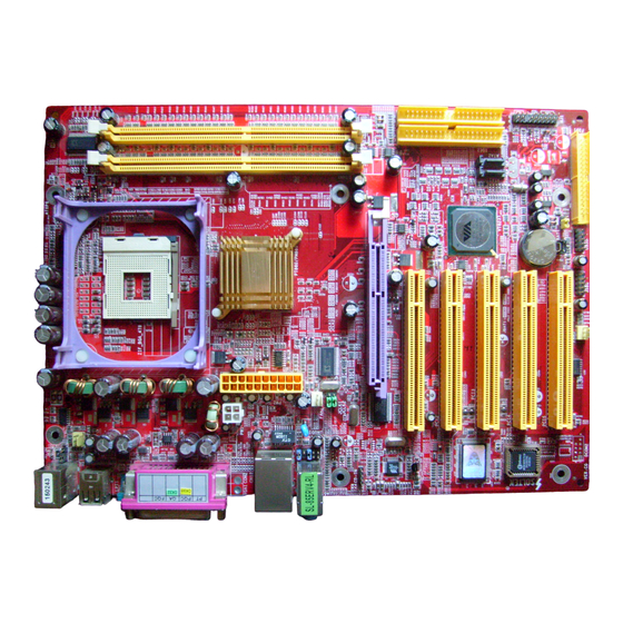
SL-85ERV4-R / 85ERV4-RL Chapter 1 Specification 1-1 85ERV4-R / 85ERV4-RL Components Locations LAN Controller for 85ERV4-RL only RJ45 LAN Connector PS/2 Mouse JKB1 (on top) Fan1 PS/2 Keyboard USB0 (underside) (on top) USB1 (2 USB ports)) +12V Power P4X533 Main Power... -
Page 7: Chipset System Block Diagram
SL-85ERV4-R / 85ERV4-RL Chapter 1 Specification 1-2 Chipset System Block Diagram Intel Pentium 4 CPU (HT & Prescott CPUs up to 3.0 GHz) System Bus 400/533/*800MHz North Bridge System Single Channel AGP 8X/4X AGP Slot Memory DDR 266/333/*400 VIA P4X533... -
Page 8: Mainboard Specifications
SL-85ERV4-R / 85ERV4-RL Chapter 1 Specification 1-3 Mainboard Specifications 1-3.1 CPU Socket CPU Socket 478B on board, supporting Intel ® Pentium 4 processors (including Intel Hyper-Threading and Prescott CPUs up to 3.0GHz) in the 478-pin package for : -- 400/533/800MHz System Bus ;... -
Page 9: 1-3.5 Bios
SL-85ERV4-R / 85ERV4-RL Chapter 1 Specification 1-3.5 BIOS Flash Memory for easy upgrade, supporting Year 2000 compliant, and sup- porting various hardware configuration during booting system (See Chapter 4 BIOS Setup): • Standard CMOS Features (Times, Date, Hard Disk Type etc,) •... -
Page 10: 1-3.8 Hardware Monitor On Board
• Hardware Monitor in IT8705F, providing monitoring and alarm for flexible desktop management of hardware voltage, temperatures and fan speeds. • Utility Software Soltek Hardware Monitor for displaying Monitoring status is enclosed in Support CD for user’s installation. 1-3.9 AC’97 Audio Codec on board AC’97 Audio Codec Version 2.2 compliant on board... -
Page 11: Chapter 2 Hardware Setup
SL-85ERV4-R / 85ERV4-RL Chapter 2 Hardware Setup Chapter 2 Hardware Setup To Get things ready for Hardware setup ! 1. We recommend to install your CPU before any other components. For detailed installation instructions of processor, you can also refer to the pamphlet enclosed in your CPU package. -
Page 12: Cpu Installation With Socket 478B
SL-85ERV4-R / 85ERV4-RL Chapter 2 Hardware Setup 2-1 CPU Installation with Socket 478B 2-1.1 To Identify a Pentium 4 CPU Intel PENTIUM 4 2.80 GHz / 512 / 800 3) System Bus 2) CPU L2 Cache 1) CPU Working Frequency On the heatsink side of a Pentium 4 CPU, there printed a line of figures to identify its specifications. -
Page 13: 2-1.2 Cpu Installation With Socket 478B
SL-85ERV4-R / 85ERV4-RL Chapter 2 Hardware Setup 2-1.2 CPU Installation with Socket 478B This mainboard is built with CPU Socket 478B (478-pin) supporting the Intel Pentium 4 CPU: • Follow the steps described in this sec- tion to install the 478-pin Pentium 4 CPU into the on board Socket 478. -
Page 14: Pentium 4 Cpu Fan Installation
SL-85ERV4-R / 85ERV4-RL Chapter 2 Hardware Setup 2-2 Pentium 4 CPU Fan Installation: Pentium 4 Fanbase CPU Fan Connector Press down 2 Spring Locks to lock fan to fanbase Connect Fan Connector to CPU FAN connector The above pictures are taken from sample mainboards as installation illustr-... -
Page 15: Memory Installation
SL-85ERV4-R / 85ERV4-RL Chapter 2 Hardware Setup 2-3 Memory Installation 2-3.1 How to tackle with the memory Modules • Make sure to unplug your Power Supply before adding or removing memory module. Failure to do so may cause severe damage to both your mainboard and the memory module. -
Page 16: Agp Slot Installation
SL-85ERV4-R / 85ERV4-RL Chapter 2 Hardware Setup 2-4 AGP slot Installation To install a VGA card into AGP 8X/4X slot on board, users can install 8X or 4X AGP card with its only card driver. An AGP 8X card will support a data transfer rate up to 2GB/sec., and an 4X card supports a date transfer rate up to 1GB/sec.. -
Page 17: Ide Connector Installation
SL-85ERV4-R / 85ERV4-RL Chapter 2 Hardware Setup 2-6 IDE Connector Installation To install IDE Connector, you may connect the blue connector of IDE cable to the primary (IDE1) or secondary (IDE2) connector on board, and then connect the gray connector to your slave device and the black connector to your master device. -
Page 18: Floppy Drive Connector Installation
SL-85ERV4-R / 85ERV4-RL Chapter 2 Hardware Setup 2-7 Floppy Drive Connector Installation To install FDD, you should connect the end of FDD cable with single connector to the board, and connect the other end with two connectors to the floppy drives. -
Page 19: Sata Raid Connectors Installation
SL-85ERV4-R / 85ERV4-RL Chapter 2 Hardware Setup 2-8 SATA RAID Connectors Installation 2 Serial ATA connectors for 2 SATA Hard Disks with RAID mode are supported by the South Bridge VIA VT8237. Please see Chapter 5 Disk Array Installation for detail RAID installaion. -
Page 20: Atx V2.03 Power Supply Installation
SL-85ERV4-R / 85ERV4-RL Chapter 2 Hardware Setup 2-9 ATX V2.03 Power Supply Installation +12V Power Connector PS/2 Mouse JKB1 (on top) Fan1 PS/2 Keyboard USB0 (underside) (on top) USB1 (2 USB ports)) +12V +12V +12V Power P4X533 Main Power Main Power... -
Page 21: Jumper Settings
SL-85ERV4-R / 85ERV4-RL Chapter 2 Hardware Setup 2-10 Jumper Settings The following diagrams show the locations and settings of jumper blocks on the mainboard. JCLK1&JCLK2: CPU Frequency Select (default) JKB1: 100MHz 133MHz *200MHz Keyboard / Mouse Wake Up Auto- (FSB400) -
Page 22: 2-10.1 Jclk1&Jclk2: Cpu Frequency Select
SL-85ERV4-R / 85ERV4-RL Chapter 2 Hardware Setup How to tackle the Jumpers: A 2-pin Jumper A 3-pin Jumper If a pin-header (of 2 or more pins) is designed in such a way that its pins can be closed or linked together to... -
Page 23: 2-10.2 Jbat1: Clear Cmos
SL-85ERV4-R / 85ERV4-RL Chapter 2 Hardware Setup Further Notes on CPU Overclocking: 1. If you have successfully booted system, with or without CPU overclock, you still can try another CPU overclock in BIOS Setup. Please enter BIOS Setup, choose “Frequency/Voltage Control” menu, and then configure the “CPU Clock”... -
Page 24: Other Connectors Configuration
SL-85ERV4-R / 85ERV4-RL Chapter 2 Hardware Setup 2-11 Other Connectors Configuration 2-11.1 Chassis Panel Connector A : PS/2 Mouse G : COM1 Connector B : LPT1 Port H : (COM2 not available) C : RJ45 (85ERV4-RL only) : 2 USB ports... -
Page 25: 2-11.3 Complex Header
SL-85ERV4-R / 85ERV4-RL Chapter 2 Hardware Setup 2-11.3 Complex Header This complex Header consists of 6 connectors providing various supports: PS/2 Mouse JKB1 (on top) Fan1 PS/2 Keyboard USB0 (underside) (on top) USB1 (2 USB ports)) +12V Power P4X533 Main Power... -
Page 26: 2-11.4 Thermal Detector
SL-85ERV4-R / 85ERV4-RL Chapter 2 Hardware Setup 2-11.4 Thermal Detector PS/2 Mouse JKB1 (on top) Fan1 PS/2 Keyboard USB0 (underside) (on top) USB1 (2 USB ports)) Thermal Detector RT2 +12V Power P4X533 Main Power RJ45 USB port USB port JAUD1... -
Page 27: 2-11.6 Usb Ports And Usb Pin-Headers
SL-85ERV4-R / 85ERV4-RL Chapter 2 Hardware Setup 2-11.6 USB Ports and USB Pin-headers This series provides four USB ports USB0 to USB3 on board sup- porting various USB devices. In addition, two USB pin-headers are added on board to provide expansion of four more optional USB ports by using two additional USB Cables. -
Page 28: 2-11.7 External Audio Connector
SL-85ERV4-R / 85ERV4-RL Chapter 2 Hardware Setup 2-11.7 External Audio Connector This Mainboard is designed with an Exter- PS/2 Mouse JKB1 (on top) Fan1 nal Audio connector “JAUD1” which pro- PS/2 Keyboard USB0 (underside) (on top) USB1 (2 USB ports)) vides connection to your chassis. -
Page 29: Chapter 3 Software Setup
SL-85ERV4-R/85ERV4-RL Chapter 3 Software Setup Chapter 3 Software Setup Drivers, Utilities and Software Installation Support CD: This mainboard will be shipped with a Support CD which contains those necessary driver files, Application Softwares and some helpful utilities. It is a user-friendly, auto-run CD which will open itself up in a CD-ROM automatically. -
Page 30: Via 4-In-1 Drivers Installation
SL-85ERV4-R/85ERV4-RL Chapter 3 Software Setup 3-2 VIA 4-IN-1 Drivers Installation 1. Following the procedures of opening the Support CD, click to “ VIA 4- in-1 Drivers” to proceed. 3. “VIA Service Pack README” 2 . T h e V I A S e r v i c e P a c k... - Page 31 SL-85ERV4-R/85ERV4-RL Chapter 3 Software Setup 6. Select “Install VIA PCI IDE 7. Select “Install VIA AGP Driver” Driver” checkbox, then click the in turbo mode and press “Next” “Next” button to continue. button to continue. Next Next 8. After all these setup procedures have finished, you should restart your computer by clicking on “OK”...
-
Page 32: To Install Ac'97 Audio Driver
SL-85ERV4-R/85ERV4-RL Chapter 3 Software Setup 3-3 To Install AC’97 Audio Driver AC97 Audio Codec VT1617 / VT1616 on board, AC’97 2.2 compatible, supporting 6 channel audio codec for PC multimedia systems. VIA AC’97 Audio Codec Driver is provided in Support CD for user’s installation. -
Page 33: 3-3.2 To Verify 6-Channel Audio
SL-85ERV4-R/85ERV4-RL Chapter 3 Software Setup 3-3.2 To verify 6-channel Audio After installation of AC’97 6-channel Codec, you must configure the 5.1 Speaker connection to enable the 6-channel audio. 1. Connect your on-board Audio Connector to your 6-channel speakers as depicted in the figure below:... - Page 34 SL-85ERV4-R/85ERV4-RL Chapter 3 Software Setup 3. Again click “Advanced“ button to enter 6 channel configuration. 4. At the “Other Controls”, pick the item “Smart 5.1 Enable” to activiate 6 channel configuration. Then click “Close” to finish configuration.
-
Page 35: Usb 2.0 Driver Installation
SL-85ERV4-R/85ERV4-RL Chapter 3 Software Setup 3-4 USB 2.0 Driver installation USB2.0 Driver is typically for Windows 98SE/ME. For Windows 2000/ XP, users can install their latest Service Pack instead of the USB2.0 driver to gain the USB2.0 support. For the Windows 98se/Me, users must install the USB2.0 driver to activate the USB2.0 support:... -
Page 36: Install Hardware Monitor Utility
SL-85ERV4-R/85ERV4-RL Chapter 3 Software Setup 3-5 Install Hardware Monitor Utility 3-5.1 Installation Hardware Monitor is built on this mainboard. Its installation is pro- grammed to a fully automated mode on Windows 9X/Me/NT4/2000/ XP. Users can follow the model installation below for its installation on various Windows System. -
Page 37: 3-5.2 Verification
SL-85ERV4-R/85ERV4-RL Chapter 3 Software Setup 3-5.2 Verification 1. After installing Soltek Hardware Monitor, double click “SoltekHM” icon on the desktop to open the main window of the Soltek Hardware Doctor. 2.Then the pop-up screen will show all information about CPU Temperature, Fan Speed and various Voltages. -
Page 38: Lan Driver Installation (For 85Erv4-Rl Only)
SL-85ERV4-R/85ERV4-RL Chapter 3 Software Setup 3-6 LAN Driver Installation (for 85ERV4-RL only) 3-6.1 Installation 1. Following the procedures of opening the Support CD, click to “ Onboard LAN Driver” to proceed. 2. Instantly, “The installation is completed” screen appears, indicating that LAN Driver setup is finished. -
Page 39: Chapter 4 Bios Setup
SL-85ERV4-R/85ERV4-RL Chapter 4 BIOS Setup Chapter 4 BIOS Setup THE BIOS BIOS stands for Basic Input and Output System. It was once called ROM BIOS when it was stored in a Read-Only Memory(ROM) chip Now manufacturers would like to store BIOS in EEPROM which means Electrically Erasable Programmable Memory. -
Page 40: About Bios Setup
SL-85ERV4-R/85ERV4-RL Chapter 4 BIOS Setup 4-1 About BIOS Setup BIOS setup is an interactive BIOS program that you need to run when: 1. Changing the hardware of your system. (For example: installing a new Hard Disk etc.) 2. Modifying the behavior of your computer. (For example: changing the system time or date, or turning special features on or off etc.) -
Page 41: To Upgrade Bios
SL-85ERV4-R/85ERV4-RL Chapter 4 BIOS Setup 4-5 To Upgrade BIOS • System BIOS is incorporated into a Flash memory component. Flash BIOS allows user to upgrade BIOS without the need to replace an EPROM component. • The Upgrade Utility can be loaded on a floppy diskette to execute saving, verifying, and updating the system BIOS. - Page 42 SL-85ERV4-R/85ERV4-RL Chapter 4 BIOS Setup Step 4. Type awdflash *.bin /sn/py/cc and then press <Enter> to run BIOS upgrade program. (*.bin depends on your mainboard model and version code. Instead of typing “*”, you should type specific file name for your specific mainboard).
- Page 43 SL-85ERV4-R/85ERV4-RL Chapter 4 BIOS Setup BIOS Update Illustration: (1) Executing the “awdflash.exe pt880.bin” in DOS system, Award Flash Memory Writer Start Screen appears: To input BIOS file name. AwardBIOS Flash Utility V8.24F (C)Phoenix Technologies Ltd. All Rights Reserved For PT880-8237-6A7L2SN9C-00 Date: 09/18/2003 File Name to Program : PT880.BIN...
- Page 44 SL-85ERV4-R/85ERV4-RL Chapter 4 BIOS Setup (4) Updating is in progress. Do not turn off power at this moment. AwardBIOS Flash Utility V8.24F (C)Phoenix Technologies Ltd. All Rights Reserved For PT880-8237-6A7L2SN9C-00 Date: 09/18/2003 Flash Type - SST 39SF020 /5V File Name to Program : pt880.bin...
-
Page 45: Bios Setup
SL-85ERV4-R/85ERV4-RL Chapter 4 BIOS Setup 4-6 BIOS SETUP --- CMOS Setup Utility Warning and Tips: If changing CMOS Configuration causes difficulty in rebooting system, you can take the following measures: 1. At pressing the power button to reboot, press the “Insert” key at the same time. - Page 46 SL-85ERV4-R/85ERV4-RL Chapter 4 BIOS Setup 3. When one main item of the Main Menu is chosen and clicked on, its submenu will appear to display the related items and options. On the other hand, a list of operation guide will appear at the end of the...
-
Page 47: 4-6.2 Standard Cmos Setup
SL-85ERV4-R/85ERV4-RL Chapter 4 BIOS Setup 4-6.2 Standard CMOS Setup Standard CMOS Setup records some basic system hardware configuration and sets the system clock and error handling. You only need to modify the configuration values of this option if you want to change your system hardware configuration or when the data stored in the CMOS memory gets lost or damaged. - Page 48 SL-85ERV4-R/85ERV4-RL Chapter 4 BIOS Setup Date (mm:dd:yy) The BIOS determines the day of the week from the other date information. This field is for information only. Press the left or right arrow key to move to the desired field (date, month, year). Press the PgUp or PgDn key to increment the setting, or type the desired value into the field.
- Page 49 SL-85ERV4-R/85ERV4-RL Chapter 4 BIOS Setup Drive A / Drive B Select this field to the type(s) of floppy disk drive(s) installed in your system. The choices are: 360KB, 5.25 in. 1.2MB, 5.25 in. 720KB, 3.5 in. 1.44MB, 3.5 in. 2.88MB, 3.5 in.
-
Page 50: 4-6.3 Advanced Bios Features
SL-85ERV4-R/85ERV4-RL Chapter 4 BIOS Setup 4-6.3 Advanced BIOS Features Advanced BIOS Features improves your system performance or sets up system features according to your preference. Run the Advanced BIOS Features as follows: Choose “Advanced BIOS Features” from the Main Menu and a screen... - Page 51 SL-85ERV4-R/85ERV4-RL Chapter 4 BIOS Setup Virus Warning When enabled, you receive a warning message if a program (specifically, a virus) attempts to write to the boot sector or the partition table of the hard disk drive. You should then run an antivirus program. Keep in mind that this feature protects only the boot sector, not the entire hard drive.
- Page 52 SL-85ERV4-R/85ERV4-RL Chapter 4 BIOS Setup Boot Up Floppy Seek When enabled, the BIOS tests (seeks) floppy drives to determine whether they have 40 or 80 tracks. Only 360-KB floppy drives have 40 tracks; drives with 270KB, 1.2MB, and 1.44MB capacity all have 80 tracks.
-
Page 53: 4-6.4 Advanced Chipset Features
SL-85ERV4-R/85ERV4-RL Chapter 4 BIOS Setup 4-6.4 Advanced Chipset Features Advanced Chipset Features is used to modify the values of chipset buffers. These buffers control the system options. Run the Advanced Chipset Features as follows: Choose “Advanced Chipset Features” from the Main Menu and a list of... - Page 54 SL-85ERV4-R/85ERV4-RL Chapter 4 BIOS Setup DRAM Clock This item allows you to set the DRAM Clock. SPD (Serial Presence Detect) is located on the memory modules, BIOS reads information coded in SPD during system boot up. Choices: By SPD; 100MHz;133MHz; 166MHz;...
-
Page 55: 4-6.4.2 Agp & P2P Bridge Control
SL-85ERV4-R/85ERV4-RL Chapter 4 BIOS Setup 4-6.4.2 AGP & P2P Bridge Control Choose “AGP & P2P Bridge Control” in “Advanced Chipset Features” and press <Enter>. The following sub-screen will appear for AGP & P2P Bridge Control configuration: AGP & P2P Bridge Control... -
Page 56: 4-6.4.3 Cpu & Pci Bus Control
SL-85ERV4-R/85ERV4-RL Chapter 4 BIOS Setup 4-6.4.3 CPU & PCI Bus Control Choose “CPU & PCI Bus Control” in “Advanced Chipset Features” and press <Enter>. The following sub-screen will appear for CPU & PCI Bus Control configuration: CPU & PCI Bus Control... -
Page 57: 4-6.5 Integrated Peripherals
SL-85ERV4-R/85ERV4-RL Chapter 4 BIOS Setup 4-6.5 Integrated Peripherals Integrated Peripherals option allows you to get some information inside your system when it is working. Run the Integrated Peripherals as follows: Choose “Integrated peripherals” from the Main Menu and a list of options... - Page 58 SL-85ERV4-R/85ERV4-RL Chapter 4 BIOS Setup IDE DMA transfer This item is to improved the whole system per- access formance with DMA mode of IDE devices enabled. On-Chip IDE Channel The chipset contains a PCI IDE interface with support from two IDE channels. Select Enabled to activate the first and/or the second IDE interface.
-
Page 59: 4-6.5.2 Via Onchip Pci Device
SL-85ERV4-R/85ERV4-RL Chapter 4 BIOS Setup 4-6.5.2 VIA OnChip PCI Device Choose “VIA OnChip PCI Device” in “Integrated Peripherals” and press <Enter>. The following sub-screen will appear for VIA OnChip PCI Device configuration: Phoenix - AwardBIOS CMOS Setup Utility VIA OnChip PCI Device... -
Page 60: 4-6.5.3 Superio Device
SL-85ERV4-R/85ERV4-RL Chapter 4 BIOS Setup 4-6.5.3 SuperIO Device Choose “SuperIO Device” in “Integrated Peripherals” and press <Enter>. The following sub-screen will appear for SuperIO Device configuration: Phoenix - AwardBIOS CMOS Setup Utility SuperIO Device Onboard FDC Controller Enabled Item Help... -
Page 61: 4-6.6 Power Management Setup
SL-85ERV4-R/85ERV4-RL Chapter 4 BIOS Setup 4-6.6 Power Management Setup Run the Power Management Setup as follows: Choose “Power Management Setup” from the Main Menu and a list of options will appear: Phoenix - AwardBIOS CMOS Setup Utility Power Management Setup... - Page 62 SL-85ERV4-R/85ERV4-RL Chapter 4 BIOS Setup Video Off Option When enabled, this feature allows the VGA adapter to operate in a power saving mode. Always On: Monitor will remain on during power saving modes. Suspend -> Off: Monitor blanked when the system enter the suspend mode.
- Page 63 SL-85ERV4-R/85ERV4-RL Chapter 4 BIOS Setup IRQ/Event Activity Detect Choose “IRQ/Event Activity Detect” in “Power Management Setup” and press <Enter>. The following sub-screen will appear for IRQ/Event Activity Detect configuration: Phoenix - AwardBIOS CMOS Setup Utility IRQ/Event Activity Detect Item Help...
- Page 64 SL-85ERV4-R/85ERV4-RL Chapter 4 BIOS Setup RTC Alarm Resume When Enabled, you can set the data and time at which the RTC (Real Time Clock) alarm awakens the system from suspend mode. Choices: Disabled; Enabled Date (of Month) Set a certain date when RTC Alarm Resume option is Enabled to awaken the system.
-
Page 65: 4-6.7 Pnp / Pci Configuration
SL-85ERV4-R/85ERV4-RL Chapter 4 BIOS Setup 4-6.7 PnP / PCI Configuration PnP/PCI Configuration allows you to modify the system’s power saving functions. Run the PnP/PCI Configuration as follows: Choose “PnP/PCI Configuration” from the Main Menu and a screen with a list of options will appear:... - Page 66 SL-85ERV4-R/85ERV4-RL Chapter 4 BIOS Setup Resource Controlled The Plug and Play Award BIOS can automatically configure all the boot and Plug and Play compatible devices. If you select Auto(default), all the interrupt request (IRQ) and DMA assignment fields will not appear, as the BIOS automatically assigns them.
-
Page 67: 4-6.8 Smartdoc Anti-Burn Shield
SL-85ERV4-R/85ERV4-RL Chapter 4 BIOS Setup 4-6.8 SmartDoc Anti-Burn Shield This section helps you to get more information about your system in- cluding CPU temperature, FAN speed and voltage. It is recommended that you contact your mainboard supplier to get proper values about the setting of the CPU temperature. -
Page 68: 4-6.9 Cpu Ratio/Voltage Control
SL-85ERV4-R/85ERV4-RL Chapter 4 BIOS Setup 4-6.9 CPU Ratio/Voltage Control Run the “CPU Ratio/Voltage Control” as following: Choose “CPU Ratio/Voltage Control” from the Main Menu and a screen with a list of options will appear: Phoenix - AwardBIOS CMOS Setup Utility... -
Page 69: 4-6.10 Load Optimized Defaults
SL-85ERV4-R/85ERV4-RL Chapter 4 BIOS Setup 4-6.10 Load Optimized Defaults When you press <Enter> on this item, you will get a confirmation dialog box with a message similar to: “ Load Optimized Defaults (Y / N) ? N ” Phoenix - AwardBIOS CMOS Setup Utility... -
Page 70: 4-6.12 Save & Exit Setup
SL-85ERV4-R/85ERV4-RL Chapter 4 BIOS Setup 3. After you enter the password, the following message appears prompt- ing you to confirm the password: “Confirm Password : “ 4. Enter the same password “exactly” the same as you have just typed to confirm the password and press <Enter>. -
Page 71: Chapter 5 Vt8237 Sata Raid
SL-85ERV4-R / 85ERV4-RL Chapter 5 VIA VT8237 RAID Chapter 5 VT8237 SATA RAID THE VIA SATA RAID Controller VT8237 & RAID Driver VIA RAID (Redundant Array of Independent Disks) Controller is built in the South Bridge VT8237. With this RAID Controller, the VIA SATA RAID BIOS is built into the system to help configure the Redundant Disk Array. -
Page 72: About Disk Array
SL-85ERV4-R / 85ERV4-RL Chapter 5 VIA VT8237 RAID 5-0 About Disk Array 5-0-1 Disk Array Interpretation A “Disk Array” is formed from a group of 2 or more disk drives with the RAID (Redundent Array of Independent Disks) technology. The aim of a Disk Array is to provide better perfornance and/or data fault tolerance. -
Page 73: First Step To Set Up Sata Raid System
SL-85ERV4-R / 85ERV4-RL Chapter 5 VIA VT8237 RAID 5-1 First Step to Set Up SATA RAID System 2 Serial ATA connectors for 2 SATA Hard Disks with RAID mode are supported by the South Bridge VIA VT8237. Please see Chapter 5 Disk Array Installation for detail RAID installaion. -
Page 74: Enable Sata-Raid Interface With System Bios
SL-85ERV4-R / 85ERV4-RL Chapter 5 VIA VT8237 RAID 5-2 Enable SATA-RAID Interface with System BIOS (1) Boot system and watch for the following initial screen to appear: VIA Technologies, Inc. VIA VT6420 RAID BIOS Setting Utility v (xxx) Copyright (C) VIA Technologies, Inc. All right reserved. -
Page 75: To Enter Via Tech. Raid Bios Setup
SL-85ERV4-R / 85ERV4-RL Chapter 5 VIA VT8237 RAID 5-3 To Enter VIA Tech. RAID BIOS Setup Reboot the system with “OnChip SATA/RAID” enabled in system BIOS Setup and watch for the following initial screen to appear: VIA Technologies, Inc. VIA VT8237 Serial RAID BIOS Setting Utility V2.10 Copyright (C) VIA Technologies, Inc. -
Page 76: Using Via Raid Bios Setup To Create Disk Array
SL-85ERV4-R / 85ERV4-RL Chapter 5 VIA VT8237 RAID 5-4 Using VIA RAID BIOS Setup to Create Disk Array (5-4-1) When you press <Enter> on the “Create Array” bar, the follow- ing screen shows up. Press <Enter>on this bar to select the RAID mode. - Page 77 SL-85ERV4-R / 85ERV4-RL Chapter 5 VIA VT8237 RAID (5-4-3) The following screen shows that RAID 0 (Striping) is selected. Now, use the “Arrow” key to mark up the “Auto Setup For Performance” bar. VIA Tech. VT8237 SATA RAID BIOS Ver 2.10...
- Page 78 SL-85ERV4-R / 85ERV4-RL Chapter 5 VIA VT8237 RAID (5-4-5) Instantly, the RAID 0 Striping mode is set up and shown on the screen. Then press <Escape> key to exit the screen. VIA Tech. VT8237 SATA RAID BIOS Ver 2.10 Set/Clear bootable array...
- Page 79 SL-85ERV4-R / 85ERV4-RL Chapter 5 VIA VT8237 RAID (5-4-7) Instantly, the Master Hard Disk is marked up. Press <Enter> on the screen to set up the “Boot Disk”. VIA Tech. VT8237 SATA RAID BIOS Ver 2.10 Set/Clear bootable array Create Array...
-
Page 80: Using Via Raid Bios Setup To Change Array Mode
SL-85ERV4-R / 85ERV4-RL Chapter 5 VIA VT8237 RAID 5-5 Using VIA RAID BIOS Setup to change Array mode (5-5-1) If you wants to change the RAID mode, say, from RAID 0 to RAID 1, you must return to the Initial RAID BIOS Setup screen. Then, press the “Arrow”... - Page 81 SL-85ERV4-R / 85ERV4-RL Chapter 5 VIA VT8237 RAID (5-5-3) When the message “The selected array will be destroied..” appears on screen, press <Y> key to continue. VIA Tech. VT8237 SATA RAID BIOS Ver 2.10 Delete a RAID array contain the...
-
Page 82: To Install Sata Raid Driver
SL-85ERV4-R / 85ERV4-RL Chapter 5 VIA VT8237 RAID 5-6 To Install SATA RAID Driver SATA-RAID Driver is incorporated in Support CD/Floppy Disk for user’s installation. The Driver Floppy Disk is needed for SATA RAID installa- tion on Windows 2K/XP. If you cannot find this Driver Floppy Disk in the mainboard package, you can make one by copying the driver from the Driver CD into a Floppy Disk. -
Page 83: To Install Sata Raid Driver On Windows 98Se/Me
SL-85ERV4-R / 85ERV4-RL Chapter 5 VIA VT8237 RAID 5-6-2 To Install SATA RAID Driver on Windows 98SE/ME (1) Get ready the Floppy Diskette holding the SATA RAID Driver. (2) Check that SATA Hard Disks are connected properly to the SATA Connectors. - Page 84 SL-85ERV4-R / 85ERV4-RL Chapter 5 VIA VT8237 RAID (11) In the “Update device Driver Wizard” screen, click “Next” to continue until you see a dialog box asking you to “Specify a location” for the driver. You should now insert the SATARAID Driver CD/Diskette into CD-ROM/Drive A.
Need help?
Do you have a question about the SL-85ERV4-R and is the answer not in the manual?
Questions and answers