Mitel 1000 Owner's Manual
Combined voice & data communications system
Hide thumbs
Also See for 1000:
- Owner's manual (88 pages) ,
- Quick reference manual (15 pages) ,
- Safety instructions (9 pages)
Table of Contents
Advertisement
Quick Links
M I T E L
3000
www.mitel.com
Owner's Manual
Global Headquarters
U.S.
Tel: +1(613) 592-2122
Tel: +1(480) 961-9000
Fax: +1(613) 592-4784
Fax: +1(480) 961-1370
For more information on our worldwide o ce locations, visit our website at www.mitel.com/o ces
THIS DOCUMENT IS PROVIDED TO YOU FOR INFORMATIONAL PURPOSES ONLY. The information furnished in this document, believed by Mitel to be accurate
as of the date of its publication, is subject to change without notice. Mitel assumes no responsibility for any errors or omissions in this document and shall
have no obligation to you as a result of having made this document available to you or based upon the information it contains.
M MITEL (design) is a registered trademark of Mitel Networks Corporation. All other products and services are the registered trademarks of their respective
holders.
© Copyright 2008, Mitel Networks Corporation. All Rights Reserved.
EMEA
CALA
Tel: +44(0)1291-430000
Tel: +1(613) 592-2122
Fax: +44(0)1291-430400
Fax: +1(613) 592-7825
Asia Paci c
Tel: +852 2508 9780
Fax: +852 2508 9232
Advertisement
Table of Contents
Troubleshooting

Related Manuals for Mitel 1000


Summary of Contents for Mitel 1000
- Page 1 THIS DOCUMENT IS PROVIDED TO YOU FOR INFORMATIONAL PURPOSES ONLY. The information furnished in this document, believed by Mitel to be accurate as of the date of its publication, is subject to change without notice. Mitel assumes no responsibility for any errors or omissions in this document and shall have no obligation to you as a result of having made this document available to you or based upon the information it contains.
-
Page 2: Table Of Contents
FCC Regulatory Information..........7 Industry Canada Regulatory Information ......9 Radio Interference ..............10 RF Radiation Exposure ............10 Basic Requirements............10 Using this Document............11 Getting to know your Mitel 1000.........12 Parts Check.................12 Front Panel................13 Connecting your Mitel 1000..........14 Digital Cordless phone range ..........14 Connecting CO lines............14 Connecting your ADSL line ..........14... - Page 3 Basic programming using the Management Application ...............22 Basic PABX Settings ............24 Date & Time Settings............30 Using Your Mitel 1000 Phone System .......31 System Description.............31 Introduction to your Mitel 1000 Phones ......31 System Featurephone ............33 Using the Cordless Telephone...........38 Featurephone– Basic Call Features ........41 Using a Standard or cordless Telephone ......49...
- Page 4 VoIP Settings ..............119 Wireless Setup / Security..........122 Firewall ................135 Diagnostics................148 Firmware Update ..............154 System Resets..............157 Configuring Your Mitel 1000 via the Featurephone..159 To enter system programming .........159 System Setup Options............159 Using Voicemail ..............171 Programming Additional System Options......176 Miscellaneous system configuration options ....177 To configure CO lines ............180...
-
Page 5: Introduction
& cordless handsets and access the latest in ‘Voice over IP’ services. This User Guide will show you how to connect Mitel 1000 and how to customize its configuration to get the most out of your new product. -
Page 6: Save These Instructions
• This product should be operated only from the type of power source indicated in the manual. If you are not sure of the type of power source to your building, consult your dealer or local Power Company. • The mains power socket outlet must be located near the product and must be easily accessible to allow plugging/unplugging. -
Page 7: Fcc Regulatory Information
FCC Regulatory Information This equipment complies with Part 68 of the FCC rules and the requirements adopted by ACTA. On the exterior of the cabinet of this equipment is a label that contains, among other information, a product identifier in the format US:LKCMF01BSIGMA If requested, this number must be provided to the telephone company. - Page 8 Toll Restriction and Least Cost Routing Equipment The software contained in Mitel 1000 to allow user access to the network must be upgraded to recognize newly established network area codes and exchange codes as they are placed into service.
-
Page 9: Industry Canada Regulatory Information
Electrical Safety Advisory It is strongly suggested that an AC surge arrestor be installed in the AC outlet to which this equipment is connected. Modifications Changes or modifications not expressly approved by the party responsible for compliance could void the user's authority to operate the equipment. -
Page 10: Radio Interference
This transmitter must not be co-located or operated in conjunction with any other antenna or transmitter. Basic Requirements In order to use all the features of the Mitel 1000 system, you must have the following: DSL service up and running on your telephone line (or an equivalent broadband Internet access). -
Page 11: Using This Document
You do not need to use a hub or switch in order to connect more than one Ethernet PC to your Mitel 1000. Instead, you can connect up to four Ethernet PCs directly to your Mitel 1000 using Note the ports labeled on the rear panel. -
Page 12: Getting To Know Your Mitel 1000
Getting to know your Mitel 1000 Parts Check In addition to this document on CD, your package should arrive containing the following: 1 Mitel 1000 Unit 1 Blue (Ethernet WAN) cable 1 Power Supply Mitel 1000 (PSU) RJ-45 1 Documentation Pack 1 Cordless handset &... -
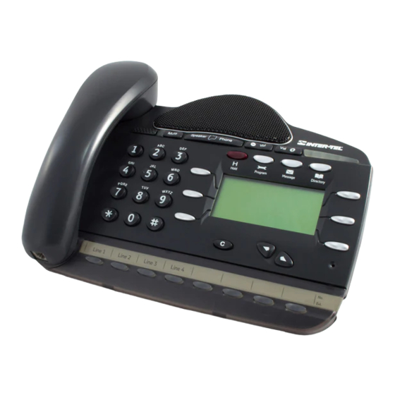
Page 13: Front Panel
Front Panel The front panel contains a ‘Page’ button and lights called Light Emitting Diodes (LEDs) that indicate the status of the Mitel 1000. Pressing the ‘Page’ button rings all the cordless handsets registered to the Mitel 1000. Label Color... -
Page 14: Connecting Your Mitel 1000
Thick stone walls will severely affect the range. symbol on your handset indicates when you are in range. If you move too far away from the Mitel 1000 during a call your phone will sound an alert tone and will flash. -
Page 15: Connecting The Power
The sets are automatically allocated a handset number (1-6) and use extension numbers (31-34). Connecting to the Internet Connect the LAN Cable (yellow) from the LAN port of your PC to any of the ETHERNET sockets of your Mitel 1000 (yellow). -
Page 16: Cabling Featurephone
The Featurephone can be connected directly to the system using the telephone cord. If you wish to locate the phone further away from the Mitel 1000 you can do so by running telephone cable and using telephone sockets. Four wires are needed to connect the Feature phones... -
Page 17: Wall Mounting The Mitel 1000
Wall Mounting the Mitel 1000 The Mitel 1000 can be wall mounted. You can print this page and use it as a template for locating the wall mounting screws supplied 1 to 1 Template (Letter size paper ) -
Page 18: Featurephone Connections (Underside Of Phone)
Featurephone connections (underside of phone) Handset connector Line cord connector Data Port Headset Port... -
Page 19: Attaching The Featurephone Desk Plinth
Attaching the Featurephone desk plinth The desk plinth allows you to mount the Featurephone at two angles. Wall mount Plinth position Plinth position 35° Plinth position 20 ° Wall-mounting a Featurephone The phone plinth is inverted on the base to wall mount the phone. Locate, drill and plug the 2 screw locations as shown below. -
Page 20: Doorphone
Line cord rails 6 inches Wall hook when the Featurephone is in a 20 degrees or 35 degrees position Wall hook when the Featurephone is wall mounted. Doorphone The doorphone is connected to extension 23. -
Page 21: Power Fail Telephone
Power Fail Telephone Connect a standard analogue telephone to the Power Fail connector. When the Mitel 1000 is switched off the CO line (Line 1) is switched through to this phone and you can make and receive calls on it until the... -
Page 22: Basic Programming Using The Management
Mitel 1000. It enables you to configure the Mitel 1000. You can access it through your web browser from any PC connected to the Mitel 1000 via the wired or wireless LAN. - Page 23 Password: admin You can change the password at any time or you can configure your Mitel 1000 so that you do not need to enter a password. See Password on page 86 Note 1. Click OK. The Welcome page is displayed: If you receive an error message or the Welcome page is not displayed, see Configuring your PCs on page 201.
-
Page 24: Basic Pabx Settings
• Basic PABX Settings. (The most common settings for the telephone system). • Router Configuration (This is only required if you are using a Cable modem or private network). • Wireless Security / Setup. (To set up a wireless connection to your PC(s). - Page 25 The Apply button must be clicked before the page is exited for the changes to take effect. The settings will be lost if this is not done. WARNING To set Night mode see page 61. Note Extension Names The settings on this page have an effect on an extension by extension basis.
- Page 26 A maximum of 10 characters per name can be entered. Voicemail Use this setting to turn ON/OFF individual voicemail boxes for each extension. The Apply button must be clicked when the names are entered and voice mail selected. Do not select any of the other options on the page until the Apply has been clicked or the settings for the names and voice mail will be lost.
- Page 27 The following restrictions can be defined on a per extension basis: • No Restrictions • Restrict International • Local Only • Emergency Calls Only • By default ALL extensions can dial ALL destinations. The Apply button, at the end of the page, must be clicked before the page is exited or any other link is selected for the changes to take effect.
- Page 28 Programming Class of Service Codes The definition of what constitutes Restricted, Allowed, National & International calls, is determined by the leading digits of the dialed number. Thus, for example, numbers beginning with ‘011xx’ are International calls. Numbers beginning one ‘1xx’ are National calls. The definition of Allowed and Restricted codes is at the user’s discretion.
- Page 29 Cordless Phone Registration The cordless extensions are shown as registered or not registered. When Register a handset is selected a prompt is displayed indicating that the ‘REG’ key on the cordless phone should be selected and that the PIN is 1234. The system is set in registration mode for 30 seconds To unregister an extension select Unregister.
-
Page 30: Date & Time Settings
Date & Time Settings Use this screen to program Time and Date settings for your system. Date Use this field to enter the system Date - the time is in the MMDDYY format, MM is the month, DD is the day, & YY is the year. For example, 3rd May 2006 =050306 Time Use this field to enter the system time - the time is in the 24- hour... -
Page 31: Using Your Mitel 1000 Phone System
The Mitel 1000 is an Integrated Communications System supporting all your voice & data needs. • The Mitel 1000 can accommodate 2 CO lines and 2 IP Trunks. • The Mitel 1000 system can accommodate 4 wired Featurephone / Standard phones, as well as 4 cordless sets. - Page 32 Getting Started This section of your Owner’s Manual is your guide to using the Mitel 1000 system and its features, with either a Featurephone or a standard telephone. It also explains how to program system settings using your Featurephone. Read the section ‘System Featurephone’ on Page 33 to understand how to operate the menus and use the other features of your Featurephone.
-
Page 33: System Featurephone
Introduction to your system Featurephone The system Featurephone are highly featured display telephones for use with your Mitel 1000 system. It features a 4-line display that contains prompts and menus with selectable options. This unique menu-driven interface makes the system simple to use, and no codes are needed to program and activate features. - Page 34 When you make an internal call, the extension number you dial is displayed. If the extension has been programmed with a name, the name is displayed. The call duration is also displayed. You can display caller numbers (or names) on your Featurephone display. The duration of external calls is displayed on the top line of the display.
- Page 35 If you are entering digits before lifting the handset, or entering text, pressing the C key deletes the last digit on the display. Using the Keypad The Keypad can be used to enter digits when dialing or text when programming names. How to enter text when programming names.
- Page 36 Using the Mute Key The Mute Key can be pressed when you are using the handset or in Speakerphone Mode. When pressed, the other person on the call cannot hear you. The Mute Key has a red light, which is lit when Mute is active. The Ringing / Message Waiting Light: There is a red light on the top right-hand corner of the Featurephone.
- Page 37 Select the required feature to be programmed onto the key. Use the Scroll Down Key ( ) to scroll down to view the list of available features. For example, to program the key with a speed dial number, select the ‘MF Digits to line’...
-
Page 38: Using The Cordless Telephone
Note Using the Cordless Telephone The cordless telephone is designed for use with the Mitel 1000. The keys are as shown. For a detailed description of the functionality see Appendix A on page184. Soft keys... - Page 39 Out of range warning: If you move too far away from the base Mitel 1000 during a call, your phone will sound an alert tone, and will flash. You need to move closer to the base Mitel 1000 or your Note call will be disconnected.
- Page 40 Answer a call When you receive a call, the phone will ring and will flash in the display. 1. Press to answer the call. Redial a number Your phone records the last 10 numbers you have dialed. The most recent call is stored at the top of the list.
-
Page 41: Featurephone- Basic Call Features
Featurephone– Basic Call Features Making and Answering Calls Making an external call. There are two basic modes of operation available for making CO Line calls. In the normal mode, which is the default, a line access digit (9 or 8) is dialed to select a Line. - Page 42 Speed Dial list Each extension can program up to 30 Individual Speed Dial numbers. You can also program 99 system speed dial numbers and names. Users of the system can access the system speed dial numbers, provided they are not restricted from dialing the number because of their Class of Service.
- Page 43 When you have selected the number or name you want a free line is automatically selected and the number is then dialed. If some numbers are entered without names they are presented at the end of the list. To answer a call When the Featurephone rings, you can do one of the following: Select ‘Answer the call’...
- Page 44 Select ‘External transfer’. Select a free line and dial the number. When the call is answered, press ‘Transfer’. Transferring an external call to an external number ties up two exchange lines. Such calls are called trunk-to-trunk calls. Note To make an external consultation call While on an external call you can contact another external number to make an enquiry, as follows: 1.
- Page 45 a) Enter an internal number if you want to Forward all your calls to another extension. b) Enter 9 followed by an external number if you want to Forward external calls to an external number. c) Forward will be ignored for internal calls. For internal calls the phone will ring (only If External forwarding is set to the 'External calls only' option).
- Page 46 Select ‘Forward when busy’. a) Enter an internal number if you want to forward all your calls to another extension. b) Enter 9 followed by an external number if you want to Forward calls to an external number. A programming option is available to allow both internal and external calls (or external calls only) to be Forwarded externally.
- Page 47 If ‘Forward On No Answer’ is enabled on an extension to forward to an external number, external incoming calls will forward, but internal calls will not. Forwarding an external call to an external number ties up two exchange lines. Such calls are called trunk- Note to-trunk calls Forwarding an external call to an external number ties up two...
- Page 48 To hold an External Conference When on a call, press the Scroll Down Key ( ) until ‘External Conference’ is displayed. Select ‘External Conference’. Select a free line and dial the external number. When the call is answered, select ‘Conference’ on the display. An external conference call ties up two exchange lines.
-
Page 49: Using A Standard Or Cordless Telephone
Using a Standard or cordless Telephone Feature Access Code List You may access the range of Mitel 1000 features with a standard or cordless telephone. To use a feature, dial the appropriate code from the list below. If your telephone is equipped with memory keys you may program feature codes onto the keys - refer to your telephone user guide for instructions. - Page 50 Making CO Line Calls There are two modes of operation available for making CO Line calls. The normal mode, which is the default, a line access digit is dialed to select a CO Line. If Automatic Line selection is programmed you do not enter the line access code.
- Page 51 To make an external consultation call While on an external call you can contact another extension to make an enquiry, as follows: While on an external call, press the Recall Key or Hookflash on your telephone. Dial the extension number. To return to the external call and place the extension on hold, press Recall or Hookflash and dial 2.
- Page 52 Cancel a Forward a call on no answer Lift handset or use Speakerphone if available Dial 734. Line Forward / Incoming Call Forwards. Forward all calls Lift handset or use Speakerphone if available. Dial 792 followed by the line number (1-4) Dial the extension number, or Dial the external phone number (including line access code 9) Followed by #.
-
Page 53: Additional Call Features
Programming and dialing speed dial numbers If you have a standard telephone, you can program up to 10 Personal Speed Dial numbers. To program a Personal Speed Dial number Lift the handset, or press the Speakerphone Key, if available. Dial the code 75. Enter the location (01 - 30) where you want to store the number. - Page 54 From a standard telephone the codes are 781 – 785 for saved numbers 2 - 6. The first saved number is the Last Number Redial code 77. Call Pick-up This feature allows the user to pick up any call, ringing at another extension. These calls include Internal calls External calls...
- Page 55 A programming option is available that disables the warning tone when barge- in is activated. See page 98 for programming from the web application and Page 164 for programming from the programming Featurephone. A further option is provided to protect extensions from “Barge-In”. See page 104 for programming from the management application and Page 163 for programming from the programming Featurephone.
- Page 56 Storing and redialing caller numbers The Caller ID service is available on CO lines. If you subscribe to this service, your network sends the telephone number of callers to the Mitel 1000 (provided the caller has not elected to restrict the network from presenting their number).
- Page 57 extension is restricted from dialing, or if there is no line available, you will hear a busy tone. If an ‘R’ is displayed on the right-hand side of a record, this indicates that the number has been redialed. If an ‘A’ is displayed on the right-hand side of a record, this indicates that the number has been answered.
- Page 58 Sending a Forward Recall while on call A Forward Recall signal may be required if you are using certain network services on standard CO lines, or if your Mitel 1000 is connected to another telephone system (PABX) via one of the line interfaces.
-
Page 59: Extension Set-Up Options
Extension Set-Up options Do Not Disturb If your extension is set to ‘Do Not Disturb’, anyone trying to call you will receive a busy (engaged) tone. If the person trying to contact you has a Featurephone, ‘Do Not Disturb Enabled’ will appear on its display. ‘Call Back’ and ‘Alarm call’... - Page 60 Dial the number you require. To change your extension Lock Password From the Idle Menu, press the Scroll Down Key ( ) until ‘Extension Lock’ is displayed. Select ‘Extension Lock’. Select ‘Change the lock code’. Dial the existing 3-digit Lock Password. The default password is 321. Dial your new 3-digit Lock Password.
-
Page 61: Incoming Call Handling
(internal dial tone). Incoming Call Handling General Calls can be presented to the Mitel 1000 on CO lines and VoIP lines. Calls can be programmed to ring any number of extensions. For configuration via the web interface, see page 94. -
Page 62: Using Voicemail
For configuration via the Featurephone interface, see page 167. Music on Hold Options When an external call is placed on hold, you can choose between supplying music, a tone, or silence to the caller. The music source can be internal, in which case it is integrated into the system and cannot be changed, or external, in which case an external source must be connected to your system. - Page 63 You are presented with the voice mail menu. The options displayed are ‘Play’, ‘Erase all messages’, ‘Greeting’, ‘Change Password’, ‘Monitor’ and ‘Cancel’. To retrieve messages left in your Voice Mailbox If new voice messages have been left in your Voice Mailbox, the Message Waiting Light, located on the top right-hand corner of your Featurephone, will be on.
- Page 64 To replay the Voice Mailbox greeting At your extension, press the MESSAGE Key. Select ‘Voice Mail’. Enter your extension number when prompted. Enter your Voicemail Password, (1111 by default), followed by #. Select ‘Greeting’. Select ‘Replay greeting’ The greeting will then be replayed for you. Transferring calls to Voice Boxes You can transfer calls to any Voice Box without calling the extension.
-
Page 65: Remote Notification Of Voice Messages
Dial 7 Go back ten seconds Dial 8 Go forward ten seconds / Skip the time stamp Dial 9 Forward the message to another extension Dial 0 Return Call. Automatically make a call to the caller who left the message (this feature is not applicable when mailbox is accessed remotely). To monitor/pick-up callers as they speak to your Voice Mailbox You can operate your voicemail in Voicemail Monitor Mode. - Page 66 The user can set up remote notification to notify them of all new messages or only those marked as priority by callers to their voice mail. Remote notification can be turned on and off as required. If the call is to a personal number the user can access their voice mail when they answer the call by entering their voice mail password and pressing #.
- Page 67 The menu updates to allow the dial string to be entered. Press “Change”. Enter the digits required by the Pager Company. Press “Confirm”. From a standard or cordless phone dial 4321 to enter the pager number and dial string. To operate voicemail from a standard telephone Standard telephones can also be allocated Voice Mailboxes.
- Page 68 You can turn the Answering Machine service on and off at any time at from any extension and its operation is independent of ’Night Service’. You can use it if you are not answering calls at lunch or at night, or simply want to record messages from callers.
-
Page 69: Programming Additional System Options
Your Mitel 1000 also features a Doorstrike relay output, which can be used to operate a Doorstrike mechanism, to allow you open the door from your extension. -
Page 70: Connecting To The Internet
Connecting to the Internet ADSL Modem configuration The Mitel 1000 is configured with all the settings that will suit your ADSL This section describes how to configure the way that your Mitel 1000 connects to the Internet. Your ISP determines what type of Internet access you should use and provides you with any information that you need in order to configure the Internet access to your Mitel 1000. - Page 71 Your ISP may also tell you to set unique path and circuit numbers (called VPI and VCI) in order to connect your Mitel 1000 to the ISP’s Internet service. In most cases, your Mitel 1000 will use default settings, so you may not need to enter these values.
- Page 72 4. Select PPPoA and Click Next>. The following page is displayed: Enter the PPP username and password provided by your ISP. Type them in the relevant boxes, and then click Next>. 5. The following page is displayed: The settings of VPI=0 and VCI=35 are the default settings.
-
Page 73: Configuring A Pppoe Adsl Connection
Your ISP may also tell you to set unique path and circuit numbers (called VPI and VCI) in order to connect your Mitel 1000 to the ISP’s Internet service. In most cases, your Mitel 1000 will use default settings, so you may not need to enter these values. - Page 74 This page displays information about your current Internet access configuration. 3. Select Change the ADSL Modem settings here. The following page is displayed 4. Select PPPoE and Click Next>. The following page is displayed: 5. Enter the PPP username and password provided by your ISP. Type them in the relevant boxes, and then click Next>.
- Page 75 You can only configure MAC spoofing if you are using PPPoE Internet access. Note If your ISP instructs you to change your Mitel 1000’s default MAC address, follow the instructions below: 1. From the Internet Access page, click Enable or disable MAC Spoofing...
-
Page 76: Configuring A Dhcp Adsl Connection - Rfc 1483
If your ISP uses a DHCP DSL connection, your ISP may tell you to set unique path and circuit numbers (called VPI and VCI) in order to connect your Mitel 1000 to the ISP’s Internet service. In most cases, your Mitel 1000 will use default settings, so you may not need to enter these values. - Page 77 From the ADSL Modem: Types of Access page select DHCP , then click Next>. The following page is displayed Select the option as indicated by your ISP. The following page is displayed Enter the VPI and VCI settings supplied by your ISP and select Next. The following page is displayed:...
- Page 78 If your ISP tells you to configure your Internet access manually, they must provide you with the following information: The WAN IP address and subnet mask for your Mitel 1000 The Internet Gateway address The primary and secondary DNS addresses You should only change the Internet Access details if your ISP asks you to, or if you are familiar with network configuration.
- Page 79 3. The following page is displayed: Select the Option provided by your ISP. The following page is displayed: 4.Enter the VPI and VCI values supplied by your ISP 5. Click Next>. The following page is displayed:...
-
Page 80: Adsl Operating Mode
This page confirms the address settings that you have manually configured (the values displayed above are for example purposes only). If you selected the Manual option at step 5, the VPI and VCI values that you entered are also displayed on this page. If you are happy with your settings, click Confirm Changes. -
Page 81: Connecting To An External Adsl Modem, Cable Modem, Lan, Wan Or Add A Host To The Dmz
Select required Mode, Click Next. The following page is displayed If you are happy with these settings, click Confirm Changes The Internet access page is displayed and your configuration is complete. Connecting to an External ADSL Modem, Cable Modem, LAN, WAN or add a host to the DMZ The WAN/DMZ port can be used to connect to an external ADSL modem, a LAN or a WAN, or to add a host to the DMZ. - Page 82 PPPoE to connect to an external ADSL modem PPPoE is used when connecting to an external ADSL modem. As the Mitel 1000 is equipped with an ADSL modem we recommend that the internal modem be used rather than an external ADSL modem.
- Page 83 3. The following screen is displayed: Select Confirm Changes. 4. The following screen is displayed: IP Gateway to connect to Cable Modem, LAN or WAN IP Gateway is typically used when connecting to a Cable Modem LAN or WAN. Select IP Gateway. Select Next. The following screen is displayed: Two options are presented: - DHCP - automatically assigns IP addresses Static - allows the IP addresses to be entered manually...
- Page 84 2. Select Confirm Changes. Static 1. Select Static. Click Next. The following screen is displayed: Enter the IP addresses and Subnet mask. Click Next. The following screen is displayed: 2. Select Confirm Changes. The following screen is displayed:...
- Page 85 A host can be connected to the WAN/DMZ Port. In default the Wan/DMZ port is configured as a DMZ. On the Router configuration page select WAN/DMZ Port. The following page is displayed: Select Change the DMZ IP address here. The following page is displayed: Enter the host IP address and subnet mask.
-
Page 86: Password
Select Confirm Changes. The following screen is displayed The DMZ setup is now complete. Password You can restrict access to your Mitel 1000’s web pages using password protection. With password protection enabled, users must enter a username and password before gaining access to the web pages. - Page 87 2. Click on Change Password settings here… The following page is displayed: 3. This page allows you to enable or disable password protection. Protection is already enabled by default. Click Next>. The following page is displayed: 4. This page displays the current username and password settings.
-
Page 88: Dhcp Server
Disabling password protection If you do not want to use password protection, follow the instructions in ‘Setting your username and password’ on page 86 and at Step 3, select Disable and then click Next>. The following page is displayed. DHCP Server A DHCP (Dynamic Host Configuration Protocol) Server is a system that assigns IP addresses to the multiple stations on the network. - Page 89 Enable/Disable The DHCP server is enabled by default. It can be disabled if required. Select ‘Disable’ to disable DHCP. DHCP Server Interfaces By default the DHCP server operates on the iplan interfaces. There is an option to delete DHCP on each interface. The DHCP Server must be disabled before an Interface can be deleted.
- Page 90 Existing DHCP Server Subnets The settings for the existing subnets on the iplan and ipdmz are displayed. All displayed parameters can be changed – change the setting to a new value and click “Apply”. To delete a subnet, check the associated box and select “Apply”. Advanced Options Select “Advanced Options”...
- Page 91 DNS Server option information The default setting is use local host as the DNS server - all DNS requests are sent to the default gateway 192.168.1.1 which then relays the request to the DNS addresses negotiated at start up. Specific DNS servers can be defined if required. Default gateway option information Use local host as default gateway is checked by default.
-
Page 92: Addressing
1. From the submenu, click on IP Addressing. The following page is displayed: This page displays the current IP address and subnet mask assigned to your Mitel 1000. The default LAN IP configuration is IP address 192.168.1.1, subnet mask 255.255.255.0. - Page 93 Your LAN PCs must remain on the same subnet as your Mitel 1000 (that is, the subnet masks must be the same) For more information about IP addresses and subnets, see IP Addresses on page 193. If necessary, reconfigure the LAN PCs so that their...
-
Page 94: Incoming Ringing
7. PABX Configuration using the web interface Your PABX (Phone System) can be completely configured via the web management system. The web management Welcome page contain a link to Basic PABX Settings, which are the configuration options that the user will most likely wish to change. - Page 95 To change the settings, select ON or OFF from the relevant drop down box for the Line/Extension configuration you require. The default is that ALL lines ring ALL wired extensions and the first four cordless phones in both Day and Night Modes.
-
Page 96: System Settings
System Settings Use this screen to program system wide settings for your system. Activate Night Service This feature allows the user to activate night service (normally out- of-hours working). Night service set-up is used to define which extension rings on incoming calls, what the Class of Service is for each extension and what type of voice greeting is played. - Page 97 System VM Capacity This setting determines the number of messages that may be stored in the answering machine. Music on Hold Source This options determines what a caller will hear when a call in placed on Hold. Select the required option below from the drop-down box. Silence Tone External –...
- Page 98 Night Service Start 2 (HHMM) The time in 24-hour clock formats (HHMM ) at which night service 2 is activated on the system. Night Service End 2 (HHMM) The time in 24-hour clock formats (HHMM ) at which night service 2 is deactivated on the system.
- Page 99 System Speed Dials You can dial your System speed dials from the relevant option on your Featurephone menu or by dialing the appropriate short code access from any analog phone. This option allows the user to enter up to 99 System speed dial numbers, which will be available to all extensions.
-
Page 100: Extension Settings
You can export files in this format using typical spreadsheet software, e.g. Microsoft Excel Extension Settings The settings on this page have an effect on an extension-by- extension basis. Individual features can be set or unset for particular extensions on the system. Basic Settings Extension Name You may assign names to extensions. - Page 101 Advanced Options Select this option to edit Advanced Options for individual extensions. Advanced Options for the cordless extensions contain only a subset of the below features, as some of the features are not Note relevant for cordless extensions.
- Page 102 Disconnect Use this option to functionally disconnect the extension from the system (this option does not physically disconnect the extension). Page Protection When selected the extension in question will not receive pages from Featurephones ‘Page-all’ calls. Individual CLI store You can program each extension to store five numbers each. Each of these extensions will have a separate record of calls that ring on CO lines programmed to ring their extensions only.
- Page 103 • External Forward Only (This setting means that ONLY incoming external calls can be Forwarded externally) It is possible that an extension may misuse the External Forward facility. The Default setting is that no extension is allowed to set the facility. WARNING Do Not Disturb If your extension is set to ‘Do Not Disturb’, anyone trying to call you...
- Page 104 Forward on No Answer The ‘Forward On No Answer’ allows you to Forward all your calls to ring at another extension if there is no answer at your extension after four rings. Alternatively, you can Forward all external calls to an external number if your extension has not answered after four rings.
- Page 105 Personal Speed Dials You can dial your personal speed dials from the relevant option on your Featurephone menu or by dialing the appropriate short code access from your analog phone. This page allows the user to enter up to 30 personal speed dial numbers for each extension.
- Page 106 In default mode, the Featurephone ‘Program Keys’ are programmed to select the external lines available on the system, the first key for Line 1 the second for Line 2 and so on. Using your mouse left click on the ‘Function’ menu option next to the Key you wish to program.
-
Page 107: Line Settings
Line Settings The settings on this page have an effect on a line-by-line basis. Individual features can be Enabled or Disabled for particular lines that are connected to the system. Equipped The system assumes that available line interfaces have external lines connected to them. -
Page 108: Line Forwarding
Advanced Options Dial Tone Detect This option requires the system to detect dial tone before calls can be made. If set to FALSE, this feature prevents the system from dropping the line when dial tone has not been detected. In this case, the line is released if no digit is dialed until the expiration of a timer. -
Page 109: Class Of Service
Because extension level forwarding only applies for calls dialed to specific extension, this feature allows you to control how to forward calls, which are received on particular lines and are not destined for a particular extension using Caller ID routing. This feature also solves the issues of which extension’s forwarding setting would take precedence in the event of an incoming call ringing multiple extensions with different Forwarding options... - Page 110 By default ALL extensions can dial ALL numbers. The Allowed and Restricted Codes The Allowed & Restricted codes can be used to add greater flexibility to how you can configure the settings. For example, if you wanted to restrict all International calls, except those to the UK (international code 01144...).
-
Page 111: Timers
Timers The timers listed below are under the control of the user and therefore can be changed from the default setting, provided the new settings is within the individual timers limits. Recall On Hold This is the time that elapses before a call, which has been placed on hold, rings back the extension that put the call on hold. -
Page 112: Lcr Programming
Ring Back Time This is the time an extension will ring when Ringback has been invoked. Answering Machine This is the time that elapses before an unanswered incoming call is presented with the System voice mailbox greeting. Voice Mail Message Length This is the maximum length of a message left in a Mailbox or a Greeting for a Mailbox, Auto Attendant or Courtesy service. -
Page 113: Cli Routes
Edit LCR Codes Using this page you may define the Least Cost Routing criteria. Up to 30 LCR rules may be defined (Index 1 – 30). In the ‘Input Code’ field you insert the relevant dialed digits (e.g. ‘00’ for International calls or ‘001’ for International calls to the USA). In the Output Code field, you insert whatever digits you want to be passed to the network. -
Page 114: Outgoing Restriction
In the number field, enter the callers number (CLI) as is delivered by the network. You may choose to associate a name with this number. Select the extension to be rung when this number is detected.. Options for Day & Night routing exist. To set the system Day & Night mode times see PABX Configuration ->... - Page 115 Local Codes The Caller ID number presented from the network is the 10 digit national number. It does not include the 1 that is required for toll calls. The system must be able to distinguish between local and toll numbers so that they can be correctly dialed from the Caller ID stores.
- Page 116 Distinctive Ringing This feature is primarily intended to support Fax. The Network Operator can provide a second number on a CO Line that rings with a different signal. The system is then programmed to ring an extension that is equipped with a Fax machine when this ringing is detected.
- Page 117 The notification type can be set to all messages or priority messages only. The user can also set this from within their voice mailbox. The notification method is whether the notification is to a normal telephone or a Pager Company. This can also be set by the extension.
- Page 118 The number of retry attempts sets the number of times the system will try to set up a call if it is not successful The line group selects the lines that will be used for the calls.
-
Page 119: Voip Settings
VoIP (or Voice over Internet Protocol) is a way to make and receive phone calls using your broadband Internet connection instead of your standard phone line. Mitel 1000 converts your phone calls into data that is sent over your high-speed Internet connection. - Page 120 Username Use this field to enter the SIP username as supplied by your VoIP service provider. The endpoint name may be any alphanumeric string of up to 50 characters. Password Use this field to enter the SIP password as supplied by your VoIP service provider.
- Page 121 The SIP registrar server expiry time interval can be any number between 1 and 86400. The timer is in seconds, and sets the frequency with which Mitel 1000 refreshes its registration with the SIP proxy server. Transport for Invite Requests...
-
Page 122: Wireless Setup / Security
This chapter assumes PCs are already equipped with a wireless card. The Wireless Network page allows you to configure the Wireless features of your Mitel 1000. From the left-hand Setup menu, click on Wireless Setup / Security. The following page is displayed:... - Page 123 The following page showing the Wireless Network name is displayed Your Mitel 1000 and all of the wireless PCs in your wireless LAN share the same wireless network name. This name (commonly known as the Service Set Identifier (SSID)) distinguishes your Wireless network from any other(s) that may be in use nearby.
- Page 124 If you want the Mitel 1000 to automatically select the best channel for your network, click on the Allow Mitel 1000 to select channel option and then click Next>. If you want to manually select a channel, click on the Select a channel manually option and then click Next>.
- Page 125 Each PC on your wireless network must be manually configured with the same key as your Mitel 1000 in order to allow wireless encrypted data transmissions. Eavesdroppers cannot access your network if they do not know your private key.
- Page 126 If you want to use WEP 128bit data encryption, click on the 128bit encryption on the wireless network radio button and then click Next>. Now follow the instructions in Configuring 64bit or 128bit encryption on page 126. If you want to use WPA, click on the Wi-Fi Protected Access (WPA) on the wireless network radio button and then click Next>.
- Page 127 Configuring WPA security Once you have selected WPA and then clicked Next>, the following page is displayed: 1. Type a unique pass phrase in the Pass phrase text box. Your pass phrase should be at least 20 characters long in order to deter potential intruders.
- Page 128 A wireless PC blacklist; PCs on this list cannot access the Mitel 1000, but all other wireless PCs can. A wireless PC whitelist; PCs on this list can access the Mitel 1000, but all other wireless PCs cannot. The Wireless PCs added to either list are identified by their unique MAC address.
- Page 129 Configuring the wireless PC blacklist 1. Once you have selected Allow all wireless PCs to connect except those I specify radio button and then clicked Next>, the following page is displayed: 2. To add a network PC to the blacklist, click Add an address here…...
- Page 130 If you are following the First Time Settings wizard, the final page in the wizard sequence is displayed, which allows you to Confirm Wireless network changes. If you have accessed this page from the General Settings section of the Wireless Network page, click on the Confirm Changes button to apply changes and return to the Wireless Network page.
- Page 131 This page confirms the configuration changes made to each page in the wizard. If you are happy with these settings, click on the Confirm Changes button. Configuration changes are applied to the Mitel 1000 and the Wireless Network page is displayed.
- Page 132 The number of valid wireless network frequencies varies from country to country and you need to identify which country you are operating the Mitel 1000 in to ensure that your network will transmit on the correct frequency. The setting for the USA is the default setting so you do not need to change it.
- Page 133 Wireless Network General Settings The General Settings section of the Wireless Network page displays details of the Mitel 1000’s current wireless configuration. For example: The hyperlinks in this section allow you to: Enable/disable wireless networking; see page 122. Change the channel currently in use; click Change your wireless channel here…...
- Page 134 (RF) energy detected by the Mitel 1000 on a specific channel. Signal strength may vary depending on the position of the PC(s) in relation to the Mitel 1000. To return to Wireless Network page, click on Return to the wireless...
-
Page 135: Firewall
Firewall The Mitel 1000 is equipped with a stateful inspection firewall. The firewall resides on the interfaces between - WAN and LAN (External and Internal) - WAN and DMZ (External and DMZ) - DMZ and LAN (DMZ and Internal) From the left-hand Setup menu, click on Network security. The following page is displayed: Select Firewall. - Page 136 Security State The Firewall is disabled by default Intrusion Detection is disabled by default. To enable the Firewall 1. Select “Enabled” 2. Select “Change State” To enable Intrusion Detection 3. Select “Enabled” 4. Select “Change State” Security Level There are three pre-defined security levels (high, medium, and low) that contain different security filters for each interface (WAN/LAN, WAN/DMZ, DMZ/LAN).
- Page 137 5060 - 6000 Medium Security Level <> <> <> Service Destination Port 0 - 65535 0 - 65535 HTTP Telnet SMTP POP3 ICMP 5060 - 6000 Low Security Level <> <> <> Service Destination Port 0 - 65535 0 -65535 HTTP Telnet SMTP...
- Page 138 Select “Disable NAT to … (Interface)” Restart the Mitel 1000 for the change to take effect Global Address Pools A range of external IP addresses can be assigned to a specific interface. Select “Advanced NAT Configuration …” The following screen is displayed Select “Add Global Address Pool …”...
- Page 139 Select an interface from the drop down list Enter an IP address and subnet mask, or enter the first and last IP addresses in the range Select “Add Global Address Pool” Reserved Mappings Static routes can be defined between an external IP address and internal IP addresses.
- Page 140 Policies, Triggers, Intrusion Detection, Logging The security policy settings, stateful inspection triggers, intrusion policy detection and logging settings can be displayed and changed. Security Policy This is used to add or delete filters Select “Security Policy Configuration …” The following screen is displayed. Select “Port Filters …...
- Page 141 - Direction, Inbound or Outbound Select “Apply” Save the new configuration Restart the Mitel 1000 Adding Raw IP Filters Filters based on IP address and protocol only can be added to the security level displayed. Select “Add Raw Filter”...
- Page 142 - IP Protocol - Direction, Inbound or Outbound Select “Apply” Save the new configuration Restart the Mitel 1000 Host Validators Traffic to or from specific hosts can be blocked by the firewall. Select “Host Validators …” for a particular interface The following screen is displayed Select “Add Host Validator …...
- Page 143 Application Level Gateways There are certain applications that NAT and Firewall configurations cannot manage. In many cases, ALGs (Application Level Gateways) are needed to translate and transport packets correctly. An ALG provides a service for a specific application such as FTP (File Transfer Protocol).
- Page 144 Select “Security Trigger Configuration …” The following screen is displayed Current security triggers are displayed. There is an option to delete each entry. Select “New Trigger” The following screen is displayed Enter the following parameters Transport Type Adds a trigger for a TCP or UDP application Port Number Start Sets the start of the trigger port range for the control session...
- Page 145 Allow Multiple Hosts Allow or Block sets whether or not a secondary session can be initiated to/from different remote hosts or the same remote host on an existing trigger Max Activity Interval The max interval time in milliseconds between the use of the secondary port sessions.
- Page 146 Enter the following parameters Use Blacklist Enables or disables blacklisting of an external host if the firewall has detected an intrusion from that host. Access is denied to that host for 10 minutes. Use Victim Protection Enables or disables the blocking of incoming broadcast Ping commands for the period specified in Victim Protection Block duration.
- Page 147 Select “Clear Blacklist” if you wish to clear all external hosts from the blacklist. Select “Apply” Save Configuration Restart the Mitel 1000 Security Logging Select “Configure Security Logging …” The following page is displayed Logging is enabled by default for Session Logging, Blocking Logging and Intrusion Logging.
-
Page 148: Diagnostics
The ADSL Test is only applicable when you are using the internal ADSL Modem to connect Mitel 1000 to the Internet. When should I run an ADSL Test? Run an ADSL Test if you cannot access the Internet. If you are... - Page 149 Logging If your system is having some problems, which are not, easily diagnosed you may be requested to enable logging. When enabled the system automatically sends detailed information to a server where specialist staff can analyze it. Select Logging on the left-hand side menu.
- Page 150 Status You can examine the settings of the WAN, DMZ, LAN, VoIP, Routing table and hardware and software. Select Status on the left-hand side menu. The following screen is displayed: - If an IP Trunk is configured but not registered an will be displayed after the Password.
- Page 151 Event Log This primarily displays recent security events e.g. blocking incoming attempts to penetrate the firewall. Ping You can Ping to defined or user defined addresses Remote Access If requested to do so you can enable Remote access to allow maintenance personnel to access the system remotely.
- Page 152 Your external IP address is shown. You provide this address to the maintenance engineer, as this is the address they use to access your system. In order to make the access secure and prevent unwanted access you also define a Password that you supply to the maintenance engineer.
- Page 153 Date : The Date the call was made Start Time : The time the call started Duration: The call duration Line : The line the call was made on Start phone : The phone that started the call Finish phone : The phone that finished the call Telephone number: The number dialed or received.
-
Page 154: Firmware Update
If there is a firmware update available you are strongly advised to install it on your Mitel 1000 to ensure that you take full advantage Note of any new feature developments. - Page 155 To restore the configuration select Browse in the restore configuration window. Select the saved file and press Restore. You will be prompted to Restart the Mitel 1000 once the file is uploaded. Firmware update Before proceeding to update the system firmware, you must have...
- Page 156 Mitel 1000. Once installation is complete, the following page is displayed: 7. You must restart your Mitel 1000 in order to make the Mitel 1000 aware that a new firmware version has been installed. To do this, click Restart.
-
Page 157: System Resets
System Resets This page allows you to reset your Mitel 1000 to its default factory settings. The configuration settings of your Mitel 1000 are stored in a configuration file. When you set up your Mitel 1000 and access the web pages for the very first time, the configuration file contains a default factory configuration. - Page 158 If you are happy with this, click in the Confirm box to tick it, then click Reset to Defaults. The following page is displayed: This page confirms that the Mitel 1000 is currently resetting to factory defaults. Once the reset is complete, Restart page is displayed.
-
Page 159: A Configuring Your Mitel 1000 Via The Featurephone
The Caller ID service is available on CO lines. If you subscribe to this service, your network sends the telephone number of callers to the Mitel 1000 (provided the caller has not elected to restrict the network from presenting their number). The telephone number (or associated name) is displayed on the ringing Featurephone. - Page 160 To set up your system to display caller numbers received on CO lines (Caller ID service) If you subscribe to the Caller Number display service from your Network Provider then you can program the system to display the callers number. From the Programming Extension, press the PROGRAM Key Press the Scroll Down Key ( ) until ‘System programming’...
- Page 161 Enter the System Programming Password and select ‘System’. Press the Scroll Down Key ( ) until ‘Caller ID List’ is displayed. Select ‘Caller ID List’. Select ‘Store All Calls’ or ‘Store Unanswered Calls’. Press the Speakerphone Key to finish programming. To set up extensions with an individual Caller ID List You can program up to twelve extensions to store five numbers each.
- Page 162 Least Cost Routing To set up codes to allow calls to be routed on specific lines or networks From the Programming Extension, press the PROGRAM Key Press the Scroll Down Key ( ) until ‘System programming’ is displayed. Select ‘System programming’. Enter the System Programming Password and select ‘Lines’.
- Page 163 Enter the System Programming Password and select ‘Extensions’. Select ‘Examine passwords’ Select ‘Ext. lock password’. Select the extension. The Lock Password is briefly displayed on the top line of the display. Press the Speakerphone Key to finish programming. Call Waiting Tone Protection Extensions may present a busy extension with a Call Waiting tone, provided the busy extension is not protected against receiving Call Waiting tones.
- Page 164 Select “System Programming”. Enter the System Programming Password and select “Extensions”. Press the Scroll Down key ( ) until “Barge-In” is displayed. Select “Barge-In Protection”. Select the extensions that are to be protected from barge-in. The extensions you select will have a “♦” displayed beside them. The default is that no extensions are protected.
- Page 165 Select the Line Select Day or Night Mode Select those extensions that are not to ring. In default all extensions are programmed to ring. A solid diamond, ♦, indicates the extensions that will ring. Restricting Outgoing Calls This feature lets you decide which lines each extension can access for outgoing calls.
- Page 166 Local Codes The Caller ID number presented from the network is the 10 digit national number. It does not include the 1 that is required for toll calls. The system must be able to distinguish between local and toll numbers so that they can be correctly dialed from the Caller ID stores.
- Page 167 Select 'On time 2' to set the second time the ‘Night Service’ turns on automatically. Select the Automatic Off times and set the two times that ‘Night Service’ is to turn off To manually turn on Night Service The Manual ‘Night Service’ feature enables you to turn ‘Night Service’...
- Page 168 Hold Options When an external call is placed on hold, you can choose between supplying music, a tone, or silence to the caller. The music source can be internal, in which case it is integrated into the system and cannot be changed, or external, in which case an external source must be connected to your system.
- Page 169 Assigning Extension Names You may assign names to extensions. When an extension receives an internal call, its display will show the calling extension name in the place of the calling extension number. To assign a name to an extension From the Programming Extension, press the PROGRAM Key Press the Scroll Down Key ( ) until ‘System programming’...
- Page 170 The emergency codes are ( 911, 060, 066, 080, 100, 101, 105, 106, 107, 110, 112, 115, 116, 118, 119, 123, 127, 128, 131, 132, 133, 156, 171, 190, 191, 192, 193, 194, 197, 198, 199, 211, 311, 511, 912, 913, 990, 999). They cannot be barred. Both Classes 5 and 6 can be associated with the same extension.
-
Page 171: Using Voicemail
Select ‘Restriction classes’. Select ‘Night Class of Service’. Select the Class you want to assign to the extensions, (Class 1 – Class 6). Enter the extensions to be entered in this Class. Press the Speakerphone Key to finish programming. To allow extensions use System Speed Dials overriding call restrictions You may wish to allow extensions to dial numbers entered in the System Speed Dial list, which they are restricted from dialing... - Page 172 Press the Scroll Down Key ( ) until ‘System programming’ is displayed. Select ‘System programming’. Enter the System Programming Password and select ‘Extensions’. Press the Scroll Down Key ( ) until ‘Voice Mail Boxes’ is displayed. Select ‘Voice Mail Boxes’ Enter the extensions to be allocated a Voice Mailbox.
- Page 173 From the Programming extension, press the PROGRAM key. Press the Scroll Down key ( ) until “System Programming” is displayed. Select “System Programming”. Enter the System Programming Password and select “System”. Select “Remote Notification”. Select “Outgoing group”. Select the group. Notification delay timer The time interval between receiving a message and making the first remote notification attempt is programmable.
- Page 174 Press the Scroll Down Key ( ) until ‘Mail box capacity’ is displayed. Select ‘VM capacity’ Enter the maximum number of messages to be stored per Mailbox. Press the Speakerphone Key to finish programming. Voice Mail capacity % used This feature tells the Administrator when the Voice Module capacity is approaching it's limit.
- Page 175 Press the Speakerphone Key to finish programming. Answering Machine This feature allows you to set up an Answering Machine to answer incoming calls. You can select which lines are to be answered by the Answering Machine when it is turned on. It can be used on both CO lines and IP Trunks.
-
Page 176: Programming Additional System Options
Press the Scroll Down Key ( ) until ‘Timers’ is displayed. Select ‘Timers’. Select ‘Answering Machine Delay ’ Enter the time. The default is 010 seconds. Press the Speakerphone Key to finish programming. Programming Additional System Options Doorphone To set up a Doorphone on your System From the Programming Extension, press the PROGRAM Key Press the Scroll Down Key ( ) until ‘System programming’... -
Page 177: Miscellaneous System Configuration Options
Select the extensions that are not allowed to activate an external forwarding or set up trunk to trunk calls. If both internal and external calls are to be Forwarded select 'All calls'. If external calls only are to be Forwarded select 'External calls only' Miscellaneous system configuration options To change the system Language The text prompts can be presented in English, French or Spanish. - Page 178 To configure disconnected extensions The system assumes that all available extension interfaces have Mitel 1000s connected to them. If an extension interface does not have a Mitel 1000 connected, ensure correct system operation by disconnecting the extension interface in system programming, as...
- Page 179 1. If you selected ‘Extension lock password’, the extension menu will appear. Select an extension and its Extension Lock Password will appear on the display. 2. If you selected ‘Voicemail password’, the extension menu will appear. Select an extension and its Voicemail Password will appear on the display.
-
Page 180: To Configure Co Lines
Inverting ringing cadences The external and Internal ringing cadences can be interchanged on an extension by extension basis. From the Programming Extension, press the PROGRAM Key Select ‘System programming’. Enter the System Programming Password and select 'Extensions'. Press the Scroll Down Key ( ) until ‘Reverse Cadence ' is displayed. - Page 181 Programming Caller ID Detection On standard CO lines on the Mitel 1000 the 'Caller ID Detection' option is programmed. The system can then detect when Caller ID information is being sent from the network and display the number. From the Programming Extension, press the PROGRAM Key Press the Scroll Down Key ( ) until ‘System programming’...
-
Page 182: To Set System Timers
Button Hopping When Button hopping is enabled if you press a second line key while on a call on another line the first call is disconnected. With button hopping off the first call is placed on hold when the second line key is pressed. -
Page 183: To Reset Your System
Forward on no answer This is the time that elapses before a call ringing at an extension, with ’Forward On No Answer’ set, is Forwarded. Open the door This is the time that the Doorstrike relay will remain open following activation. -
Page 184: B Cordless Phone Detailed Instructions
TV and radio sets, clock radios and computers if placed too close. It is recommended that you position the Mitel 1000 at least one meter from such appliance Use only the mains adapter supplied with this telephone. Incorrect adapter polarity or voltage can seriously damage the telephone. - Page 185 The information in your shared phonebook is stored in System Speed dial list in the Mitel 1000. The information is shared by all the handsets cordless and wired. See system speed dial on page 42 on the programming of the list from a Featurephone.
- Page 186 To store a name and number in the private phonebook Press NAMES. Select the private phonebook and press OK. Select ADD ENTRY, and then press OK. Enter the name for the record. You must enter a name. Enter the number. In the Private phone book the line access code 9 or 8 must be entered.
- Page 187 Delete a quick dial key Press NAMES. Select PRIVATE, and then press OK. Select QUICK DIAL, and then press OK. The first quick dial key is displayed. Scroll to the quick dial key you wish to delete. Press OPTIONS. and select DELETE. Press OK. CONFIRM? is displayed.
- Page 188 3. Press OK. A list of call records is displayed. Scroll through the list. 4. Press OPTIONS. Select DETAILS. Press OK. Transfer the call records to your private phonebook You can transfer the call records to your private phonebook 1. Press the CALLS Key 2.
- Page 189 Press SAVE. Duplicate name You cannot enter an identical name for different records in your services directory. If so, DUPLICATE NAME is displayed. Press OK to replace the existing record with the new entry or press CANCEL to return to the previous display and make changes to the name. Delete all of the services directory 1.
- Page 190 2. Select DISPLAY. Press OK. 3. Select WALLPAPER. Press OK. 4. Select the wallpaper. Press OK to confirm. Change the display color Change the color of the menus, highlight, and background of your phone to your color. 1. Press MENU. 2.
- Page 191 To set the alarm clock on, press OK and continue to step 5. To set the alarm clock off, press OK to confirm. 5. Press to set the hour. Press . Press to set the minute. If your phone’s time format is set to 12 hours, go to step 7.
- Page 192 Press PAUSE. The stopwatch pauses counting. Press RESUME to start the stopwatch again from the paused time. Press CANCEL. The stopwatch is deactivated. Using touch & dial Touch & dial allows you to call a number by pressing any key (except CANCEL) on your handset.
-
Page 193: Cip Addresses, Network Masks & Subnets
IP Addresses, Network Masks & Subnets IP Addresses This section refers only to IP addresses for IPv4 (version 4 of the Internet Protocol). IPv6 addresses are not covered. This section assumes basic knowledge of binary numbers, bits, Note and bytes. IP addresses, the Internet's version of telephone numbers, are used to identify individual nodes (computers or systems) on the Internet. -
Page 194: Subnet Masks
Class B networks are smaller but still quite large, each able to hold over 65,000 hosts. There can be up to 16,384 class B networks in existence. A class B network might be appropriate for a large organization such as a business or government agency. Class C networks are the smallest, only able to hold 254 hosts at most, but the total possible number of class C networks exceeds 2 million (2,097,152 to be exact). -
Page 195: D Glossary
A DHCP relay is a computer that forwards DHCP data between computers that request IP addresses and the DHCP server that assigns the addresses. Each of the Mitel 1000’s interfaces can be configured as a DHCP relay. See DHCP. Dynamic Host Configuration Protocol server... - Page 196 server looks up the requested domain name to find its corresponding IP address. If the DNS server cannot find the IP address, it communicates with higher-level DNS servers to determine the IP address. See domain name. A domain name is a user-friendly name used in place of its domain name associated IP address.
- Page 197 A network limited to a small geographic area, such as a home or small office. Light Emitting Diode An electronic light-emitting device. The indicator lights on the front of the Mitel 1000 unit are LEDs. Media Access Control address MAC address The permanent hardware address of a device, assigned by its manufacturer.
- Page 198 A protocol for serial data transmission that is used to carry IP (and other protocol) data between your ISP and your computer. The WAN interface on the Mitel 1000 uses two forms of PPP called PPPoA and PPPoE. See PPPoA, PPPoE.
- Page 199 IP address of another interface. For example, the WAN unnumbered interface of your Mitel 1000 uses the same IP address of the LAN interface (192.168.1.1). The unnumbered interface is temporary – PPP or DHCP will assign a ‘real’...
- Page 200 The encrypted data can only be sent and received by users with access to a private network key. Each PC on your wireless network must be manually configured with the same key as your Mitel 1000 in order to allow wireless encrypted data transmissions.
-
Page 201: E Configuring Your Pcs
If you have connected your LAN PCs via Ethernet to Mitel 1000, follow the instructions that correspond to the operating system installed on your PC: If you want to allow Wireless PCs to access your Mitel 1000, see section on Wireless Setup / Security on page 122. Windows® XP PCs 1. - Page 202 CD or other media. Follow the instructions to install the files. 8. If prompted, click OK to restart your computer with the new settings. Next, configure the PCs to accept IP information assigned by Mitel 1000: 9. In the Control Panel, double-click the Network and Dial-up Connections icon.
- Page 203 CD. Follow the instructions to install the files. 9. Click OK to restart the PC and complete the TCP/IP installation. Next, configure the PCs to accept IP information assigned by Mitel 1000: 10. Open the Control Panel window, and then click the Network icon.
- Page 204 The IP address and subnet mask of each PC The IP address of the default gateway for your LAN. In most cases, this is the address assigned to the LAN port on Mitel 1000. By default, the LAN port is assigned the IP address 192.168.1.1.
- Page 205 computer, DNS server and default gateway, click the radio buttons that enable you to enter the information manually. Your PCs must have IP addresses that place them in the same subnet as the LAN port. Note Setting up your browser not to use a proxy server 1.
-
Page 206: F Troubleshooting
Go to (d) Is the Ethernet LED on? Verify that your PC is connected to LAN port 1, 2, 3 or 4 on the Mitel 1000 using a Cat 5 patch cord or cable. (c) For a Wireless Go to (d) - Page 207 (2) Check your ADSL settings (a) Enter the Mitel 1000 Main menu • Select Router Configuration • Select ADSL Modem click Change the ADSL Modem settings here … • Select PPPoA click Next • Enter PPP Username, PPP Password, retype password click Next •...
- Page 208 The following procedure assumes that the WLAN has been set up with WPA security. If a different security configuration has been set up, refer back to Section 10 Wireless Setup/Security (a) Enter the Mitel 1000 Main menu • Select Wireless Settings/Security In General Settings...
- Page 209 (5) Check your Wireless PC settings The following procedure is for a PC with an Intel (PRO) Wireless Network adapter that has been set up for WPA security. For other Wireless Network adapters, consult the manufacturer’s user manual. Note that some older wireless adapters do not support WPA. •...
-
Page 210: Troubleshooting Your Cordless Phone
- Try plugging the base (crackles, echo, electrical appliance. unit to a different etc.) - Mitel 1000 unit is installed in a location. room with thick walls. - Install the base unit in - The handset is too far from a different room. -
Page 211: Troubleshooting The Pabx
Power Fail socket found on the back of the Mitel 1000. There will be no internal service, no Broadband connection, Wireless LAN access or Cordless telephone service until the power is restored. - Page 212 Noise from the Featurephone speaker. There is an option on the Mitel 1000 to play the music you provide for music on hold through the Featurephone speakers when the Featurephone is not being used. This feature can only be used when you provide an external music source.
- Page 213 THIS DOCUMENT IS PROVIDED TO YOU FOR INFORMATIONAL PURPOSES ONLY. The information furnished in this document, believed by Mitel to be accurate as of the date of its publication, is subject to change without notice. Mitel assumes no responsibility for any errors or omissions in this document and shall have no obligation to you as a result of having made this document available to you or based upon the information it contains.
Need help?
Do you have a question about the 1000 and is the answer not in the manual?
Questions and answers
I would like to know how to clear voicemails on all the phone extensions used with this console.
Enter your Voicemail Password (default is 1111) followed by #. In the Voice Messaging Control Menu, select "Erase all messages" to clear voicemails on all Mitel 1000 phone extensions.
This answer is automatically generated