Table of Contents
Advertisement
Advertisement
Table of Contents

Related Manuals for Mitel TA7102


Summary of Contents for Mitel TA7102
- Page 1 Mitel TA7102 INSTALLATION GUIDE...
- Page 2 Mitel or any of its affiliates or subsidiaries. Mitel and its affiliates and subsidiaries assume no responsibility for any errors or omissions in this document. Revisions of this document or new editions of it may be issued to incorporate such changes.
-
Page 3: Table Of Contents
SAFETY RECOMMENDATIONS REQUIRED MOUNTING TOOLS AND EQUIPMENT UNPACKING AND INSPECTION LOCATION AND MOUNTING REQUIREMENTS HARDWARE INSTALLATION POWERING ON THE TA7102 ........................... 21 IP ADDRESS DISCOVERY OR CONFIGURATION INDICATORS (LEDS) RESET/DEFAULT BUTTON MANAGEMENT CHOICES APPENDIX A – STANDARD COMPLIANCE AND SAFETY INFORMATION ..........32... -
Page 4: About This Manual
IP Telephony offering to residential or SME markets. DOCUMENT OBJECTIVES The TA7102 Hardware Installation Guide provides technical information on how to physically install the TA7102. It also describes the cabling required for the TA7102 device. The information included in this guide consists of: ... -
Page 5: Document Structure
Lists the various standards compliance of the Safety TA7102. Information” “Appendix B - Cabling Considerations” Describes the pin-to-pin connections for cables used with the TA7102. “Appendix C - Standard Hardware Lists the technical hardware information of the Information” TA7102. 153/1531-ANF 901 14 B 2017-03-08... -
Page 6: Document Conventions
TA7102 Hardware Installation DOCUMENT CONVENTIONS The following information provides an explanation of the symbols that appear on the TA7102 and in the documentation for the product. Warning Definition Warning: Means danger. You are in a situation that could cause bodily injury. Before you work on any equipment, you must be aware of the hazards involved with electrical circuitry and be familiar with standard practices for preventing accidents. - Page 7 TA7102 Hardware Installation For more information on and a list of RFCs and Internet-Drafts, refer to the IETF web site at http://www.ietf.org. 153/1531-ANF 901 14 B 2017-03-08...
-
Page 8: Overview
This chapter describes the TA7102 connectors and indicators. Provider-specific profiles ensure that the TA7102 is a genuine plug and play solution. It offers a low total cost of ownership as it reduces installation and maintenance costs. Moreover, the TA7102 integrates features such as TLS, SRTP, and HTTPS designed to bring enhanced security for network management, SIP signaling and media transmission aspects. -
Page 9: Connectors And Indicators
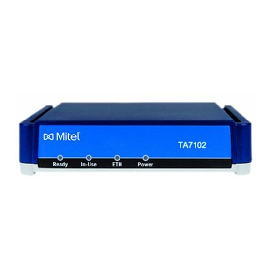
The serial number label for the TA7102 device is located on the bottom of the unit. Front Indicators and Connectors See “Indicators (LEDs)” for a description of the LED patterns the TA7102 may have and the states they represent. Figure 1 shows the four visual indicators located on the front of the TA7102. - Page 10 In Use When lit, at least one of the FXS lines is in use. Provides the state of the network connected to the WAN and LAN connectors. Power When lit, power is applied to the TA7102. 153/1531-ANF 901 14 B 2017-03-08...
- Page 11 TA7102 Hardware Installation Rear Connectors The TA7102 has several connections that must be properly set. Figure 2 shows the rear panel of the TA7102. Standards Supported - ITU-T I.430 Basic user-network interface - Layer 1 specification (section 9). Figure 2: TA7102 Rear Panel Connectors Table 3 describes the rear panel connections (from left to right).
- Page 12 TA7102 Hardware Installation Power connector External 12 Vdc power supply. 153/1531-ANF 901 14 B 2017-03-08...
-
Page 13: Installation
Install the hardware and software needed to configure the TA7102 (see section“Network Information”). Installation Checklist The installation checklist lists the tasks for installing the TA7102. Print a copy of this checklist and mark the entries as you complete each task. Include the completed checklist in your site log. - Page 14 Initial configuration performed Initial operation verified Site Log Mitel recommends that you maintain a site log to record all actions relevant to the TA7102, such as: Installation: Print a copy of the installation checklist and insert it into the site log.
-
Page 15: Safety Recommendations
The following are safety recommendations and best practices to follow when working with the TA7102. Maintaining Safety with Electricity Warning: Do not work on the TA7102, connect or disconnect cables during periods of lightning activity. Warning: Disconnect all power before servicing the TA7102. -
Page 16: Required Mounting Tools And Equipment
Warning: To prevent fire or shock hazard do not expose the unit to rain or moisture. The TA7102 is suited for use in an office or residential environment where it can be wall-mounted or free standing. - Page 17 Water or moisture that could enter the casing of the TA7102. The airflow is not restricted around the TA7102 or through the vents of the unit. The unit requires a minimum of 25 mm (1 in.) clearance. ...
- Page 18 6. Proceed to Hardware Installation. Free Standing Unit When installing the TA7102 on a desk or table, it should be located at least 20 cm from your monitor, computer casing or other peripherals, including speakers. Never put books or paper on the TA7102.
- Page 19 If this occurs, allow the unit to acclimatize for an hour before powering it on. Cleaning To clean the TA7102, wipe with a soft dry cloth. Do not use volatile liquids such as gas and thinner that are harmful to the unit casing.
-
Page 20: Hardware Installation
MDI / MDIX detection. See RJ-45 Cable for more details. Connect the power cord to the TA7102. Do not yet connect the other end of the power cord to an electrical outlet. You are now ready to start the TA7102. -
Page 21: Powering On The Ta7102
Note that the TA7102 IPv6 interface is disabled by default. Once the physical connection is complete and the TA7102 is powered up, you must first find out the IP address the TA7102 is using. The TA7102's IP address can be set either dynamically or statically. The default behavior of the TA7102 is to try to obtain a dynamic IP address through a DHCP server. - Page 22 TA7102 so that it is easily accessible. Note: If the Power LED is always blinking and never turns on, this means that the TA7102 cannot find either an IPv4 DHCP server or an IPv6 address automatically. Check that you have a DHCP server properly configured on your network.
- Page 23 TA7102 so that it is easily accessible. Insert a small, unbent paper clip into the Reset / Default hole located at the rear of the TA7102. The Power LED will start blinking, and after a few seconds, all the LEDS will start blinking. Release the paper clip after all the LEDs start blinking and before they all stop blinking (between 7-11 seconds).
- Page 24 Current IP address of the TA7102 (static or DHCP). *#*1 MAC address of the TA7102. Verifying the Installation There are a few ways to verify that the TA7102 is properly connected to the IP network and is working: By contacting it with a SNMP browser ...
-
Page 25: Indicators (Leds)
INDICATORS (LEDS) The indicators (LEDs) of the TA7102 are described in TA7102 Connectors and Indicators. LED Patterns – Specific Conditions Table 5 describes the different states a Mitel unit can have and their associated LED patterns. Table 5: LED Patterns CondiCondition... - Page 26 TA7102 Hardware Installation UpdateFailed Triggered after a failure of a firmware All LEDs: pack download operation. After 4 • blinking at 3Hz, seconds, the unit restarts. • 50% duty. One LED out of two has a 180 degree phase. This pattern lasts for 8 seconds.
-
Page 27: Reset/Default Button
The RESET/DEFAULT button allows you to: Cancel an action that was started. Revert to known factory settings if the TA7102 refuses to work properly for any reason or the connection to the network is lost. Reconfigure a unit. - Page 28 You can use the RESET/DEFAULT button at start-time – you power the unit off, and then depress the button until the LEDs stop blinking and remain ON. This applies the “Factory Reset” procedure (see Factory Reset). This feature reverts the TA7102 back to its default factory settings. 153/1531-ANF 901 14 B 2017-03-08...
- Page 29 TA7102 Hardware Installation Partial Reset The Partial reset provides a way to contact the TA7102 in a known and static state while keeping most of the configuration unchanged. Following a partial reset, the TA7102 management interface is set to the Rescue interface. The default address for this interface is 192.168.0.1/24 and has its corresponding link-local IPv6 available and printed...
- Page 30 The Factory reset creates a new configuration file with the default factory values. It should be performed with the TA7102 connected to a network with access to a DHCP server. If the unit cannot find a DHCP server, it sends requests indefinitely.
-
Page 31: Management Choices
1. Power the TA7102 off. 2. Insert a small, unbent paper clip into the Reset / Default hole located at the rear of the TA7102. While pressing the Reset / Default button, restart the unit. Do not depress before the LEDs stop blinking and are steadily ON. -
Page 32: Appendix A - Standard Compliance And Safety Information
Connect the equipment into an outlet on a circuit different from that to which the receiver is connected. Consult the dealer or an experienced radio/TV technician for help Note: Any changes or modifications not expressly approved Mitel could void the user’s authority to operate the equipment. - Page 33 TA7102 Hardware Installation DECLARATION OF CONFORMITY Please contact your Mitel office or Sales partner. 153/1531-ANF 901 14 B 2017-03-08...
-
Page 34: Translated Warning Definition
TA7102 Hardware Installation TRANSLATED WARNING DEFINITION The following information provides an explanation of the symbols which appear on the TA7102 and in the documentation for the product. Warning: Means danger. You are in a situation that could cause bodily injury. Before you work on any equipment, you must be aware of the hazards involved with electrical circuitry and familiar with standard practices for preventing accidents. -
Page 35: Safety Warnings
TA7102 Hardware Installation SAFETY WARNINGS This section lists the following safety warnings: Circuit Breaker (20A) Warning TN Power Warning Product Disposal Warning No. 26 AWG Warning WAN, LAN, Phone-Fax 1 and Phone-Fax 2 Connectors Warning ... -
Page 36: Safety Recommendations
TA7102 Hardware Installation Socket Outlet Warning Warning: The socket outlet, if used, shall be located near the equipment and shall be easily accessible by the user. The AC adaptor inlet is considered as disconnection device. The device must be readily operational. -
Page 37: Appendix B - Cabling Considerations
For example, a straight cable is required to connect the TA7102 to a hub or a switch, while a crossover cable is required to connect the TA7102 to a PC. - Page 38 TA7102 Hardware Installation Table 10: RJ-45 Pinout Information Colour Coding EIA/TIA 568B AT&T 258A Pin # Function EIA/TIA 568A Transmit + White with green stripe White with orange stripe Green with white stripe or solid Orange with white stripe or solid...
- Page 39 TA7102 Hardware Installation Table 11: Pin Name and Function Pin # Name Function Transmit Data Positive signal for the TD differential pair. This signal Plus contains the serial output data stream transmitted onto the network. Transmit Data Negative signal for the TD differential pair. This contains the Minus same output as pin 1.
-
Page 40: Telephone) Cable
TA7102 Hardware Installation RJ-11 (TELEPHONE) CABLE The RJ-11 cable is commonly used for telephone connection. Caution: Do not plug a phone jack connector into an RJ-45 port. Wiring Conventions For telephone connections, a cable requires one pair of wires. Each wire is identified by different colours. - Page 41 TA7102 Hardware Installation EIA/TIA-IS 968 CS-03 Issue 8, Part III requirements. Warning: The RJ-11 cable should comply with UL 1863 and CSA C22.2 No 233 standards. 153/1531-ANF 901 14 B 2017-03-08...
-
Page 42: Appendix - C Standard Hardware Information
Mitel sales representative to obtain the latest version of the technical specifications. INDUSTRY STANDARD PROTOCOLS The TA7102 has been designed to support all major industry standards used today, as well as those that will eventually be implemented at a later date. Because of this specific design characteristic, the TA7102 can be integrated with existing telephone, fax and data equipment such as PCs and routers. - Page 43 TA7102 Hardware Installation • • DiffServ • 802.1p • 802.1Q 153/1531-ANF 901 14 B 2017-03-08...
-
Page 44: Hardware Features
TA7102 Hardware Installation HARDWARE FEATURES Interfaces 2 x RJ-11 connectors, analog phone/fax (FXS) interface 2 x RJ-45 connectors, 10/100 BaseT Ethernet access (autosense: up to 100 Mbits) Power External 12 Vdc power supply (wall plug or desktop, based on country/area model). -
Page 45: Analog Line Interface (Fxs)
TA7102 Hardware Installation Protocols Group 3 Fax Clear channel (G.711), G.726 or T.38 Real Time Fax Over IP protocol Stack Fax Data Compression Fax Transmission Up to 14.4 kbps ANALOG LINE INTERFACE (FXS) RJ-11 connectors Direct connection to a fax machine or telephone (Internal installation and internal cabling) ... -
Page 46: Audio Specifications
TA7102 Hardware Installation AUDIO SPECIFICATIONS Software-adjustable dynamic and static jitter buffer protection. Programmable by country: Call progress tone generation including dial tone, busy tone, ringback and error tones. DSP-based echo control device. Silence detection/suppression level software adjustable. -
Page 47: Power Consumption
7.10 MTBF VALUE The Mean Time Before Failure (MTBF) value of the TA7102 models is 750,000 hours. These values are at 25 degrees Celsius ambient temperature. It has been defined using RelCalc v5.0, Bellcore method (LimitedStress - Method I, Case 3), Desktop unit excluding the power adaptor. -
Page 48: Dimensions And Weight
TA7102 Hardware Installation 7.12 DIMENSIONS AND WEIGHT Table 20: Dimensions and Weight Parameter Description Dimensions 3.1 cm x 12.7 cm x 9.9 cm - 1.2 in. x 5 in. x 3.9 in. (approx.) Weight 170 g (0.37 lb) 153/1531-ANF 901 14 B 2017-03-08... -
Page 49: Appendix D - Glossary
TA7102 Hardware Installation APPENDIX D - GLOSSARY 10 BaseT An Ethernet local area network that works on twisted pair wiring. 100 BaseT A newer version of Ethernet that operates at 10 times the speed of a 10 BaseT Ethernet. Domain Name Server (DNS) Internet service that translates domain names into IP addresses. - Page 50 TA7102 Hardware Installation A standard describing software that keeps track of the Internet’s addresses for different nodes, routes outgoing messages, and recognizes incoming messages. Light Emitting Diode (LED) A semiconductor diode that emits light when a current is passed through it.
- Page 51 TA7102 Hardware Installation Server A computer or device on a network that works in conjunction with a client to perform some operation. Session Initiation Protocol (SIP) A protocol for transporting call setup, routing, authentication, and other feature messages to endpoints within the IP domain, whether those messages originate from outside the IP cloud over SCN resources or within the cloud.
-
Page 52: Appendix E - List Of Acronyms
TA7102 Hardware Installation APPENDIX E – LIST OF ACRONYMS American Wire Gauge Cummunauté européenne (French) DHCP Dynamic Host Configuration Protocol Domain Name Server IETF Internet Engineering Task Force Internet Protocol Local Area Network ma milliampere Media Access Control Media Dependent Interface... - Page 53 TA7102 Hardware Installation 153/1531-ANF 901 14 B 2017-03-08...
Need help?
Do you have a question about the TA7102 and is the answer not in the manual?
Questions and answers