Table of Contents
Advertisement
Quick Links
Advertisement
Chapters
Table of Contents

Related Manuals for Icom IC-GM651


Summary of Contents for Icom IC-GM651
- Page 1 INSTRUCTION MANUAL VHF MARINE TRANSCEIVER iGM651 Ver. 1.004...
-
Page 2: Important
IC-GM651. We want to take a couple of moments of your time to thank you for making the IC-GM651 your radio of choice, and hope you agree with Icom’s philosophy of “technology first.” Many EXPLICIT DEFINITIONS hours of research and development went into the design of your IC-GM651. -
Page 3: Precautions
Icom optional equipment is designed for optimal perfor- mance when used with this transceiver. We are not respon- KEEP the transceiver at least 1 m away from the ship’s sible for the transceiver being damaged or any accident navigation compass. -
Page 4: In Case Of Emergency
IN CASE OF EMERGENCY INSTALLATION NOTE If your vessel requires assistance, contact other vessels and The installation of this equipment should be made in such a the Coast Guard by sending a Distress call on Channel 16. manner as to respect the EC recommended electromagnetic field exposure limits (1999/519/EC). -
Page 5: Firmware Version Number
The firmware version number is displayed in the opening screen as below. The version number is also displayed when MMSI code check screen is selected. (see p. 18) Firmware version number indication (This illustration describes ‘Version 1.000’.) IC-GM651 <MMSI> 123456789 Ver1.000... -
Page 6: Table Of Contents
TABLE OF CONTENTS 4 DUALWATCH/TRI-WATCH ............14 FOREWORD ..................i IMPORTANT ..................i n Description ................14 EXPLICIT DEFINITIONS ..............i n Operation ................14 PRECAUTIONS ................ii 5 SCAN OPERATION ............15–17 IN CASE OF EMERGENCY ............iii n Scan types ................15 INSTALLATION NOTE ..............iii n Setting TAG channels ............16 FIRMWARE VERSION NUMBER ............ - Page 7 n Transmitting DSC calls ............50 n Received messages ..............92 D Transmitting an All Ships call ..........50 D Distress message ..............92 D Transmitting an Individual call ..........52 D Other messages ..............95 D Transmitting an Individual Acknowledgement call ....54 n DSC Set mode ...............99 D Transmitting a Group call ...........60 D Printing out the DSC memory contents ......99 D Transmitting a Position Request call ........62...
-
Page 8: Table Of Contents
TABLE OF CONTENTS (Continued) 8 CONNECTIONS AND MAINTENANCE......109–117 n Connections .................109 n Antenna ................110 n Fuse replacement ..............110 n Supplied accessories ............111 D Accessory connectors set up ...........111 n Power supply connections ...........112 D Connecting to the DC power supply through the PS-250 ...112 D Connecting to the AC outlet through the PS-250 and optional PS-240 ............113 n Mounting the transceiver .............114... -
Page 9: Operating Rules
OPERATING RULES D PRIORITIES (2) OPERATOR’S LICENSE A Restricted Radiotelephone Operator Permit is the license • Read all rules and regulations pertaining to priorities and most often held by small vessel radio operators when a radio keep an up-to-date copy handy. Safety and Distress calls is not required for safety purposes. -
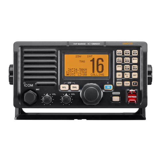
Page 10: Panel Description
PANEL DESCRIPTION n Panel description Function display (p. 5) !1 SELECTOR !2 CHANNEL 16/ DIAL CALL CHANNEL KEY VHF MARINE iGM651 Speaker !3 KEYPAD !0 TRANSMIT POWER KEY o VOLUME CONTROL q CLEAR KEY MMSI w FUNCTION KEY DIAL i MIC CONNECTOR e DISTRESS KEY r DSC MENU KEY u SQUELCH CONTROL... - Page 11 PANEL DESCRIPTION t POWER KEY [POWER] (p. 8) o VOLUME CONTROL [VOL] (p. 8) ➥ Push to turn power ON and OFF. Rotate to adjust the audio level. • The transceiver does not turn power ON when the connected !0 TRANSMIT POWER KEY [H/L] PC-250 is turned OFF.
- Page 12 PANEL DESCRIPTION ➥ Number input: ‘1’ ➥ Number input: ‘7’ ➥ Comment input: ‘Q,’ ‘Z,’ ‘q,’ ‘z’ or space ➥ Comment input: ‘P,’ ‘R,’ ‘S,’ ‘p,’ ‘r’ or ‘s’ ➥ After pushing [F], push to turn the Dualwatch function ON or OFF. (p. 14) ➥...
-
Page 13: Function Display
PANEL DESCRIPTION n Function display !0 POWER !1 DUPLEX INDICATOR INDICATOR !2 CHANNEL GROUP INDICATOR o BUSY/TRANSMIT q CALL CHANNEL INDICATOR INDICATOR BUSY 25W CALL i TAG CHANNEL INDICATOR w MESSAGE INDICATOR u SCAN INDICATOR NORMAL SCAN e CHANNEL NUMBER 34°34.506N y POSITION READOUT... -
Page 14: Panel Description
PANEL DESCRIPTION t TIME ZONE INDICATOR i TAG CHANNEL INDICATOR (p. 16) ➥ Shows the current time data when a GPS receiver is Appears when a TAG channel is selected. connected. o BUSY/TRANSMIT INDICATOR • “??” and the last received time data may blink alternately ➥... -
Page 15: Basic Operation
BASIC OPERATION n Channel selection D Call channel D Channel 16 Each regular channel group has a separate leisure-use call Channel 16 is the distress and safety channel. It is used for channel. The call channel is monitored during Tri-watch. The establishing initial contact with a station and for emergency call channels can be programmed (p. -
Page 16: D International Channels (Depends On Version)
BASIC OPERATION n Receiving and transmitting D International channels (Depends on version) There are pre-programmed 57 international channels for the IC-GM651. CAUTION: Transmitting without an antenna will dam- age the transceiver. q Push [DIAL] to select a regular channel. w While pushing and holding [H/L], push [DIAL] to change q Push [POWER] to turn power ON. - Page 17 BASIC OPERATION y Push and hold [PTT] to transmit, then speak into the mi- t Select the e Change the r Select a crophone. output power channel group channel • “TX” appears. • Channel 70 cannot be used for transmission other than DSC. u Release [PTT] to receive.
-
Page 18: Call Channel Programming
BASIC OPERATION n Call channel programming e Push and hold [⁄6 • C] again for 3 sec. (until a long beep You can program the call channel with your most often-used channels in each channel group for quick recall. changes to 2 short beeps) to enter call channel program- ming condition. -
Page 19: Channel Comments
BASIC OPERATION n Channel comments Memory channels can be labeled with a unique alphanu- Push meric ID of up to 10 characters each. Capital letters, small letters, 0 to 9, some symbols (- . /) and space can be used. Input the channel 34°34.506N 123°23.236W... -
Page 20: Microphone Lock Function
BASIC OPERATION n Microphone lock function r Push [ENT] to input and set the comment. • The cursor and the character stop blinking. The microphone lock function elec- trically locks [Y]/[Z] and [HI/LO] keys on the optional microphone. 34°34.506N This prevents accidental channel 123°23.236W changes and function access. -
Page 21: Backlight Function
Without this function, water may muf- ness can be adjusted as follows. fle the sound coming from the speaker. The IC-GM651 emits a low beep tone when this function is ➥ After pushing [F], push [3• ] then rotate [SELECTOR] activated. -
Page 22: Dualwatch/Tri-Watch
DUALWATCH/TRI-WATCH n Description n Operation Dualwatch monitors Channel 16 while you are receiving q Select the desired channel. on another channel; Tri-watch monitors Channel 16 and the w Push [F], then push [1• ] to start Dualwatch or DUAL call channel while receiving another channel. Dualwatch/Tri- [2•... -
Page 23: Scan Operation
SCAN OPERATION n Scan types Set the TAG channels (scanned channel) before scanning. Scanning is an efficient way to locate signals quickly over a wide frequency range. The transceiver has Priority scan and Clear the TAG for unwanted channels which inconveniently stop scanning, such as those for digital communication use. -
Page 24: Setting Tag Channels
SCAN OPERATION n Setting TAG channels n Starting a scan For more efficient scanning, add the desired channels as Set scan type (Priority or Normal scan) and scan resume TAG channels or clear the TAG for unwanted channels. timer in advance using Set mode. (p. 107) Channels that are not tagged will be skipped during scan- q While pushing and holding [H/L], push [DIAL] several ning. -
Page 25: Scan Operation
SCAN OPERATION [Example]: Starting a normal scan. 34°34.506N 123°23.236W UTC 12:00 INTL Push then push Scan starts. NORMAL SCAN 34°34.506N 123°23.236W UTC 12:00 Appears When a signal is received BUSY 25W NORMAL SCAN 34°34.506N 123°23.236W UTC 12:00 SAFETY... -
Page 26: Dsc Operation
DSC menu screen appears after pushing [MENU•MMSI]. MMSI Input Rotate Firmware version number indication 123______ Cursor moves (This illustration describes ‘Version 1.000’.) SELECTOR MMSI Push IC-GM651 MMSI Input <MMSI> 123456789 No MMSI Ver1.000 After 2 sec. MMSI Input _________ 1st digit blinks... -
Page 27: Dsc Address Id
DSC OPERATION n DSC address ID e After inputting the MMSI code, push [ENT]. A total of 100 DSC address IDs can be programmed and • ‘Confirmation’ line appears. named with up to 10 characters. NOTE: The transceiver automatically returns to the nor- MMSI Input mal operation condition when no operation is performed 123456789... - Page 28 DSC OPERATION r Input the 9-digit individual ID directly with the keypad. t Input the 10-character of the individual ID name directly • Rotate [SELECTOR] to move the cursor backward or forward. with the keypad. • Push [CE] to clear the ID and name. •...
- Page 29 DSC OPERATION y Push [ENT] to program and return to the DSC set up menu. i Rotate [SELECTOR] to select “Exit,” push [ENT] to re- turn to the normal operation condition. --DSC Menu-- • Pushing [CLR] also returns to the normal operation condition. Add:Individual ID Input 9 Digits --DSC Menu--...
-
Page 30: D Deleting Individual Id
DSC OPERATION D Deleting Individual ID r Rotate [SELECTOR] to select the desired ID name for q Push [MENU] to enter the DSC menu. deleting, push [ENT]. w Rotate [SELECTOR] to select “Set up,” push [ENT]. • Push [CLR] to cancel and back to the previous screen. --DSC Menu-- Select Item --DSC Menu--... -
Page 31: D Programming Group Id
DSC OPERATION D Programming Group ID y Push [CLR] to return to the DSC Set up menu. q Push [MENU] to enter the DSC menu. • Push [ENT] to delete the selected individual ID. (see step t) w Rotate [SELECTOR] to select “Set up,” push [ENT]. •... - Page 32 DSC OPERATION r Input the 8-digit group ID directly with the keypad. t Input the 10-character of the group ID name directly with • Rotate [SELECTOR] to move the cursor backward or forward. the keypad. • Push [CE] to clear the ID and name. •...
- Page 33 DSC OPERATION y Push [ENT] to program and return to the DSC Set up i Rotate [SELECTOR] to select “Exit,” push [ENT] to re- menu. turn to the normal operation condition. • Pushing [CLR] also returns to the normal operation condition. --DSC Menu-- Add:Group ID --DSC Menu--...
-
Page 34: D Deleting Group Id
• Push [CLR] to cancel and back to the previous screen. --DSC Menu-- --DSC Menu-- Select Item Rotate Select ID Distress Call ≤ Rotate Icom Received Call Log Group A Position Request SELECTOR ˘Group B Test Call SELECTOR Group C ˘Set up... -
Page 35: Position And Time Programming
DSC OPERATION n Position and Time programming y Push [CLR] to return to the DSC Set up menu. • Push [ENT] to delete the selected group ID. (see step t) A Distress call should include the ship’s position and time •... - Page 36 DSC OPERATION e Input your latitude data directly with the keypad. After in- r Input your longitude data directly with the keypad. After putting, push [ENT] to set. inputting, push [ENT] to set. • Push [6• ] to input N; North latitude or [7• ] to input •...
- Page 37 DSC OPERATION NOTE: When no position and time data are input, the fol- t Input the current UTC time with the keypad. After input- lowing screen appears. Push [ENT] to set. ting, push [ENT] to set. • Rotate [SELECTOR] to move the cursor backward or forward. •...
-
Page 38: Position And Time Indication
: 12:00 MNL 12:00 CALLING A GPS receiver appropriate for the IC-GM651 is not supplied from Icom. A GPS receiver with IEC61162-1: 2000 format When no position and time data are set. is required for position and time indication. Ask your dealer about suitable GPS receivers. -
Page 39: Gps Information Indication
DSC OPERATION n GPS information indication ➥ When the connecting GPS receiver is compatible with When a GPS receiver (IEC61162-1: 2000 format) is con- several sentence formatters, the order of input prece- nected, the transceiver displays the GPS information after pushing and holding [ENT] for 1 sec. -
Page 40: Distress Call
DSC OPERATION n Distress call D Simple call A Distress call should be transmitted, if in the opinion of the Master, the ship or a person is in distress and requires im- q Confirm no Distress call is being received. mediate assistance. - Page 41 DSC OPERATION e After transmitting the call, the transceiver waits for an ac- ➥ A distress alert contains (default); knowledgment call. • Nature of distress : Undesignated distress • Position data : GPS or manual input position data held • The Distress call is automatically transmitted every 3.5 to 4.5 for 23.5 hrs.
-
Page 42: D Regular Call
DSC OPERATION D Regular call When the transceiver receives the GPS data from the The nature of the distress should be included in the Distress call. connected GPS receiver, the following screens (steps e q Push [MENU] to enter the DSC menu, then rotate [SE- to t) do not appear. - Page 43 DSC OPERATION r Input your longitude data directly with the keypad (if you want to t Input the current UTC time data directly with the keypad change the displayed data). After inputting, push [ENT] to set. (if you want to change the displayed data). After inputting, •...
- Page 44 DSC OPERATION NOTE: When no position and time data are input, the fol- y Push and hold [DISTRESS] for 3 sec. to transmit the Dis- lowing screen appears. Push [ENT] to set. tress call. • Emergency channel (Channel 70) is automatically selected and •...
- Page 45 DSC OPERATION ➥ The Distress call is repeated every 3.5–4.5 min., until re- u After transmitting the Distress call, the transceiver waits for an acknowledgment call. ceiving an ‘acknowledgement.’ (‘Distress Call Repeat’ • The Distress call is automatically transmitted every 3.5 to 4.5 mode;...
-
Page 46: D Transmitting A Distress Cancel
DSC OPERATION • About the ‘Distress Call Repeat’ mode D Transmitting a Distress Cancel The Distress call is automatically repeated every 3.5–4.5 Distress Cancel call operation is available only when the min., until receiving an ‘acknowledgement.’ transceiver is waiting for an ‘acknowledgement’ call after To cancel the ‘Distress Call Repeat’... -
Page 47: D Transmitting A Distress Acknowledgement Call
DSC OPERATION D Transmitting a Distress Acknowledgement call Distress call reception should stop after one sequence since the coast station should send back an ‘acknowledgement’ to Distress Cancel the ship. If the distress call continues even the coast station Are You Sure? send back an ‘acknowledgement,’... -
Page 48: Dsc Operation
DSC OPERATION e The distress information appears. Push [ENT]. t After transmitting the Distress Acknowledgement call, the transceiver selects the Channel 16 automatically. --DSC Menu-- Distress Information Rotate Distress ID 121111113 Undesignated SELECTOR LAT: 12°23.111N LON:123°23.123E 34°34.506N UTC:10:25 ≥ 123°23.236W UTC 12:00 CALLING Telephony... -
Page 49: D Transmitting A Distress Relay Call
DSC OPERATION D Transmitting a Distress Relay call q Push [MENU] to enter the DSC menu, then rotate There are two ways to transmit the distress relay call— “DROBOSE ( )” and [SELECTOR] to select “Distress Relay,” push Distress Relay On Behalf Of Someone Else [ENT]. - Page 50 DSC OPERATION e Rotate [SELECTOR] to select the desired pre-pro- r Distress ID of the ship in distress selection screen grammed coast station address or “Manual Input” appears. Rotate [SELECTOR] to select “Manual for transmitting a distress relay call, push [ENT]. Input,”...
- Page 51 DSC OPERATION y Rotate [SELECTOR] to select the nature of the distress, t Input the 9-digit Distress ID (MMSI ID) code of the ship in distress that you wish to help with the keypad. push [ENT]. • Rotate [SELECTOR] to move the cursor backward or forward. •...
-
Page 52: 34°34.506N
DSC OPERATION u Your position data is displayed. Input the ship in distress i Input the ship in distress longitude data directly with the latitude data directly with the keypad. After inputting, push keypad. After inputting, push [ENT] to set. [ENT] to set. - Page 53 DSC OPERATION NOTE: When no position and time data are input, the fol- o Input the current UTC time with the keypad. After input- ting, push [ENT] to set. lowing screen appears. Push [ENT] to set. • If the data is not necessary to be changed, push [ENT] to skip •...
- Page 54 DSC OPERATION !0 Push [ENT] to transmit the distress relay call. To transmit the distress relay call with “Distress Call Log”: • Emergency channel (Channel 70) is automatically selected. You can relay a distress call after receiving the distress call. Distress Relay --DSC Menu-- Transmission...
-
Page 55: Rotate Select Address
DSC OPERATION r Distress ID of the ship in distress selection screen ap- When “All Ships” is selected, step e does not ap- pears. Rotate [SELECTOR] to select the desired distress pear. Go to step r. ID from the distress call log, push [ENT]. e Rotate [SELECTOR] to select the desired pre-pro- --DSC Menu-- grammed coast station address or “Manual Input”... -
Page 56: D Transmitting A Distress Relay Acknowledgement Call
DSC OPERATION y Push [ENT] to transmit the distress relay call. D Transmitting a Distress Relay Acknowledgement call • Emergency channel (Channel 70) is automatically selected. Distress relay acknowledgement call operation is available only when the distress relay call is received. --DSC Menu-- Distress Relay q Push [MENU] to enter the DSC menu, then rotate... - Page 57 DSC OPERATION e The distress information appears. Push [ENT]. t After transmitting the Distress Relay Acknowledgement call, the transceiver selects the Channel 16 automatically. --DSC Menu-- Rotate Distress Relay Info From Station 1 Distress ID SELECTOR 121212121 Undesignated LAT: 12°23.111N 34°34.506N LON:123°23.123E ≥...
-
Page 58: Transmitting Dsc Calls
DSC OPERATION n Transmitting DSC calls To ensure correct operation of the DSC function, please w Rotate [SELECTOR] to select the desired category, push make sure you set the squelch correctly. (p. 102) [ENT]. Rotate --DSC Menu-- D Transmitting an All Ships call Select Category Large ships use Channel 70 as their ‘listening channel.’... - Page 59 DSC OPERATION r Push [ENT] to transmit the All ships call. t After the All ships call has been transmitted, the trans- • Emergency channel (Channel 70) is automatically selected. ceiver selects the traffic channel (specified in step e) • If Channel 70 is busy, the transceiver stands by until the chan- automatically.
-
Page 60: D Transmitting An Individual Call
DSC OPERATION D Transmitting an Individual call q Push [MENU] to enter the DSC menu, then rotate The Individual call function allows you to transmit a DSC sig- [SELECTOR] to select “Individual Call,” push nal to a specific coast station or ship only. After transmission, [ENT]. - Page 61 DSC OPERATION When “Manual Input” is selected, set the 9-digit indi- r Rotate [SELECTOR] to select the desired intership chan- vidual ID you wish to call with the keypad, push [ENT]. nel or “Manual Input,” push [ENT]. • Intership channels are already preset into the transceiver in Push --DSC Menu-- recommended order.
-
Page 62: D Transmitting An Individual Acknowledgement Call
DSC OPERATION t Push [ENT] to transmit the Individual call. D Transmitting an Individual Acknowledgement call • Emergency channel (Channel 70) is automatically selected. When receiving an Individual call, you can transmit an ac- • If Channel 70 is busy, the transceiver stands by until the chan- knowledgement call (‘Able to comply’, ‘Propose New Chan- nel becomes clear. - Page 63 DSC OPERATION To transmit “Able to Comply”— Manual ACK: q Push [MENU] to enter the DSC menu, then rotate e The call information appears, push [ENT]. [SELECTOR] to select “Individual ACK,” push [ENT]. --DSC Menu-- • “Individual ACK” is added to the DSC menu after receiv- Individual Call Info ing an Individual call.
- Page 64 DSC OPERATION t Push [ENT] to transmit the Individual acknowledgement To transmit “Propose New Channel”— Quick ACK: call to the calling station. ➥ After an Individual call is received, push [CLR] to stop the alarm, then rotate [SELECTOR] to indicate the received •...
- Page 65 DSC OPERATION w Rotate [SELECTOR] to select the desired individual ad- t Rotate [SELECTOR] to select a desired intership channel dress or ID code, push [ENT]. or “Manual Input,” push [ENT]. • Intership channels are already preset into the transceiver in --DSC Menu-- recommended order.
- Page 66 DSC OPERATION y Push [ENT] to transmit the Individual acknowledgement To transmit “Unable to Comply”— Quick ACK: call to the calling station. ➥ After an Individual call is received, push [CLR] to stop the alarm, then rotate [SELECTOR] to indicate the received •...
-
Page 67: Rotate [Selector] To Select The Desired Individual Ad
DSC OPERATION w Rotate [SELECTOR] to select the desired individual ad- r Rotate [SELECTOR] to select “Unable to Comply,” dress or ID code, push [ENT]. push [ENT]. --DSC Menu-- --DSC Menu-- Rotate Select Address Select Action Rotate ˘Station 1 Able to Comply Station 2 Propose New Channel SELECTOR... -
Page 68: D Transmitting A Group Call
DSC OPERATION y Push [ENT] to transmit the Individual acknowledgement D Transmitting a Group call call to the calling station. The Group call function allows you to transmit a DSC signal • Emergency channel (Channel 70) is automatically selected. to a specific group only. •... -
Page 69: Rotate [Selector] To Select A Desired Intership Channel
DSC OPERATION w Rotate [SELECTOR] to select the desired pre-pro- e Rotate [SELECTOR] to select a desired intership channel grammed group address or “Manual Input,” push or “Manual Input,” push [ENT]. [ENT]. • Intership channels are already preset into the transceiver in recommending order. -
Page 70: D Transmitting A Position Request Call
DSC OPERATION D Transmitting a Position Request call r Push [ENT] to transmit the Group call. Transmit a Position Request call when you want to know a • Emergency channel (Channel 70) is automatically selected. specific ship’s current position, etc. •... -
Page 71: Manual Input
DSC OPERATION w Rotate [SELECTOR] to select the desired pre-programmed e Push [ENT] to transmit the Position Request call. individual address or “Manual Input,” push [ENT]. • Emergency channel (Channel 70) is automatically selected. • If Channel 70 is busy, the transceiver stands by until the chan- •... -
Page 72: D Transmitting A Position Reply Call
DSC OPERATION D Transmitting a Position Reply call w Rotate [SELECTOR] to select the desired individual ad- Transmit a Position Reply call when a Position Request is dress or ID code, push [ENT]. received. (p. 87) --DSC Menu-- To transmit a “Position Reply”— Quick ACK: Rotate Select Address ➥... -
Page 73: Continue To The Next Page
DSC OPERATION r Input your latitude data directly with the keypad. After in- t Input your longitude data directly with the keypad. After putting, push [ENT] to set. inputting, push [ENT] to set. • If the data is not necessary to be changed, push [ENT] to skip •... - Page 74 DSC OPERATION NOTE: When no position and time data are input, the fol- y Input the current UTC time with the keypad. After input- ting, push [ENT] to set. lowing screen appears. Push [ENT] to set. • If the data is not necessary to be changed, push [ENT] to skip •...
-
Page 75: D Transmitting A Polling Reply Call
DSC OPERATION u Push [ENT] to transmit the Position Reply call to the call- D Transmitting a Polling Reply call ing station. Transmit a Polling Reply call when a Polling Request is re- • Your position data is transmitted, when [ENT] is pushed. ceived (p. -
Page 76: Dsc Operation
DSC OPERATION To transmit “Polling Reply”— Manual ACK: q Push [MENU] to enter the DSC menu, then rotate r Push [ENT] to transmit the Polling Reply call to the calling [SELECTOR] to select “Polling Reply,” push [ENT]. station. • “Polling Reply” is added to the DSC menu after receiving •... -
Page 77: D Transmitting A Medical Transports Call
DSC OPERATION D Transmitting a Medical Transports call q Push [MENU] to enter the DSC menu, then rotate The medical transports call informs all ships, by urgency pri- [SELECTOR] to select “Medical Transports,” ority, that your ship is carrying a patient in need of a medical push [ENT]. -
Page 78: D Transmitting A Neutral Ship Call
DSC OPERATION e Push [ENT] to transmit the Medical Transport call. D Transmitting a Neutral Ship call • Emergency channel (Channel 70) is automatically selected. The Neutral Ship call informs all ships that your ship is a • If Channel 70 is busy, the transceiver stands by until the chan- neutral (not a participant) in armed conflict. - Page 79 DSC OPERATION e Push [ENT] to transmit the Neutral Ship call. q Push [MENU] to enter the DSC menu, then rotate [SE- • Emergency channel (Channel 70) is automatically selected. LECTOR] to select “Neutral Ship,” push [ENT]. • If Channel 70 is busy, the transceiver stands by until the chan- •...
-
Page 80: D Transmitting A Test Call
DSC OPERATION D Transmitting a Test call w Rotate [SELECTOR] to select the desired pre-programmed Testing on the exclusive DSC distress and safety calling individual address or “Manual Input,” push [ENT]. channels should be avoided as much as possible by using •... - Page 81 DSC OPERATION e Push [ENT] to transmit the Test call. t When receiving the acknowledgement call, “Received • Emergency channel (Channel 70) is automatically selected. Test ACK” appears in the display. See p. 91 for details. • If Channel 70 is busy, the transceiver stands by until the chan- nel becomes clear.
-
Page 82: D Transmitting A Test Acknowledgement Call
DSC OPERATION D Transmitting a Test Acknowledgement call w Rotate [SELECTOR] to select the desired individual ad- Transmit a Test Acknowledgement call when a Test call is dress or ID code, push [ENT]. received (p. 90). Rotate --DSC Menu-- To transmit a “Test Acknowledgement”— Quick ACK: Select Address ➥... -
Page 83: Receiving Dsc Calls
DSC OPERATION n Receiving DSC calls r Push [ENT] to transmit the Test Acknowledgement call to the calling station. D Receiving a Distress call • Emergency channel (Channel 70) is automatically selected. q While monitoring Channel 70 and a distress call is received: •... - Page 84 DSC OPERATION IMPORTANT! Distress call reception should stop after w Rotate [SELECTOR] to indicate the received message one sequence since the coast station should send back log information. an ‘acknowledgement’ to the ship. • Push [CLR] to ignore the call and exit the condition. e Rotate [SELECTOR] to scroll.
-
Page 85: D Receiving A Distress Acknowledgement Call
DSC OPERATION D Receiving a Distress Acknowledgement call e Rotate [SELECTOR] to scroll. q While monitoring Channel 70 and a Distress acknowl- • Push [CLR] to cancel and back to the previous screen. edgement call to other ship is received: •... -
Page 86: D Receiving A Distress Cancel
DSC OPERATION D Receiving a Distress Cancel e Rotate [SELECTOR] to scroll. q While monitoring Channel 70 and a Distress Cancel is received: • Push [CLR] to cancel and back to the previous screen. • Push [F], then push [8• ] to print out the received mes- •... -
Page 87: D Receiving A Distress Relay Call
DSC OPERATION D Receiving a Distress Relay call e Rotate [SELECTOR] to indicate the received message q While monitoring Channel 70 and a Distress Relay call is log information. received: • Push [CLR] to cancel and back to the previous screen. •... -
Page 88: D Receiving A Distress Relay Acknowledgement Call
DSC OPERATION D Receiving a Distress Relay Acknowledgement call e Rotate [SELECTOR] to indicate the received message q While monitoring Channel 70 and a Distress Relay ac- log information. knowledgement call is received: • Push [CLR] to cancel and back to the previous screen. •... -
Page 89: D Receiving An All Ships Call
DSC OPERATION D Receiving an All Ships call e The received message log is displayed. q While monitoring Channel 70 and an All Ships call is re- • Push [CLR] to cancel and back to the previous screen. ceived: • Push [F], then push [8• ] to print out the received mes- •... -
Page 90: D Receiving An Individual Call
DSC OPERATION D Receiving an Individual call e The received message log is displayed. q While monitoring Channel 70 and an Individual call is re- • Push [CLR] to cancel and back to the previous screen. ceived: • Push [F], then push [8• ] to print out the received mes- •... -
Page 91: D Receiving An Individual Acknowledgement Call
DSC OPERATION D Receiving an Individual Acknowledgement call When receiving “Able to Comply”: e The received message log is displayed. q While monitoring Channel 70 and an Individual acknowl- • Push [CLR] to cancel and back to the previous screen. edgement call “Able to comply”... - Page 92 DSC OPERATION When receiving “Propose New Channel”: q While monitoring Channel 70 and an Individual acknowl- e The received message log is displayed. • Push [CLR] to cancel and back to the previous screen. edgement call “Able to comply” is received: •...
- Page 93 DSC OPERATION When receiving “Unable to Comply”: q While monitoring Channel 70 and an Individual acknowl- e The received message log is displayed. • Push [CLR] to cancel and back to the previous screen. edgement call “Unable to comply” is received: •...
-
Page 94: D Receiving A Group Call
DSC OPERATION D Receiving a Group call e The received message log is displayed. q While monitoring Channel 70 and a Group call is re- • Push [CLR] to cancel and back to the previous screen. ceived: • Push [F], then push [8• ] to print out the received mes- •... -
Page 95: D Receiving A Position Request Call
DSC OPERATION D Receiving a Position Request call e The received message log is displayed. q While monitoring Channel 70 and a Position Request call • Push [CLR] to cancel and back to the previous screen. is received: • Push [F], then push [8• ] to print out the received mes- •... -
Page 96: D Receiving A Position Reply Call
DSC OPERATION D Receiving a Position Reply call e Rotate [SELECTOR] to scroll the indicated information. q While monitoring Channel 70 and a Position Reply call is • Push [CLR] to cancel and back to the previous screen. received: • Push [F], then push [8• ] to print out the received mes- •... -
Page 97: D Receiving A Polling Request Call
DSC OPERATION D Receiving a Polling Request call e The received message log is displayed. q While monitoring Channel 70 and a Polling Request call • Push [CLR] to cancel and back to the previous screen. is received: • Push [F], then push [8• ] to print out the received mes- •... -
Page 98: D Receiving A Test Call
DSC OPERATION D Receiving a Test call e The received message log is displayed. q While monitoring Channel 70 and a Test call is received: • Push [CLR] to cancel and back to the previous screen. • The alarm sounds depending on the received category. •... -
Page 99: D Receiving A Test Acknowledgement Call
DSC OPERATION D Receiving a Test Acknowledgement call e The received message log is displayed. q While monitoring Channel 70 and a Test Acknowledge- • Push [CLR] to cancel and back to the previous screen. ment call is received: • Push [F], then push [8• ] to print out the received mes- •... -
Page 100: Received Messages
DSC OPERATION n Received messages w Rotate [SELECTOR] to select “Distress.” The transceiver automatically stores up to 20 distress mes- sages and 20 other messages. • The received messages are stored in “Distress” in DSC menu if its category or format specifier is ‘Distress.’ The stored messages are automatically deleted after 48 hours has passed from storing. - Page 101 DSC OPERATION r Rotate [SELECTOR] to scroll the selected message. In case of the Distress Acknowledgement call • The stored message has various information depending on the --DSC MENU-- type of Distress call. Rotate • Push [ENT] to select the channel 16. Distress ACK ≤...
- Page 102 DSC OPERATION In case of the Distress Cancel In case of the Distress Relay Acknowledgement call --DSC MENU-- --DSC MENU-- Rotate Rotate Distress Cancel ≤ Distress Relay ACK ≤ From 121111113 To Individual SELECTOR SELECTOR Distress ID From Station 2 121111113 Distress ID Undesignated...
-
Page 103: D Other Messages
DSC OPERATION D Other messages q Push [MENU] to enter the DSC menu, then rotate e Rotate [SELECTOR] to scroll to the desired message, [SELECTOR] to select “Received Call Log,” push push [ENT]. [ENT]. • Messages which are blinking have not read yet. •... -
Page 104: All Ships Call ≤ From Station
DSC OPERATION In case of the Individual Acknowledgement call In case of the All Ships call ‘Able to Comply’ --DSC MENU-- Rotate --DSC MENU-- All Ships Call ≤ Rotate From Station 1 Individual ACK ≤ SELECTOR Safety From Station 1 Telephony SELECTOR Routine... - Page 105 DSC OPERATION In case of the Position Request call In case of the Polling Request call --DSC MENU-- --DSC MENU-- Position Request Polling Request From Station 1 From Station 1 Safety Routine • Push [ENT] to reply the call. (p. 64) •...
- Page 106 DSC OPERATION In case of the Test Acknowledgement call --DSC MENU-- Test ACK From Station 1 Safety Push to Exit • Push [ENT] to exit the condition. When [CE] is pushed, the following screen appears. Push [ENT] to delete the selected log data. --DSC Menu-- Log Deletion Are You Sure?
-
Page 107: Dsc Set Mode
DSC OPERATION n DSC Set mode D Programming Individual ID/Group ID w Rotate [SELECTOR] to select “Auto Print,” push [ENT]. (See pgs. 19, 23) D Deleting Individual ID/Group ID --DSC Menu-- (See pgs. 22, 26) Set Up Add:Group ID ≤ Rotate DEL:Individual ID D Printing out the DSC memory contents... -
Page 108: D Position Automatic Acknowledgement
DSC OPERATION D Position Automatic Acknowledgement e Rotate [SELECTOR] to select the position automatic ac- This item sets the position automatic acknowledgement function to ON or OFF. knowledgement function ON or OFF. When a position request, polling request or test call is re- --DSC Menu-- ceived, the transceiver automatically transmits a position Position Auto ACK... -
Page 109: D Dsc Data Output
DSC OPERATION D DSC Data Output e Rotate [SELECTOR] to select the DSC Data Output func- Select a DSC Data Output function from List Station, All Sta- tion or OFF. tion from List Station, All Station or OFF. • List Station : Outputs the position data from the specified sta- When receiving position acknowledgment or DSC call in- tions listed in the DSC individual ID screen. -
Page 110: D Squelch Level Setting For Channel 70 Receiver
DSC OPERATION D Squelch Level Setting for Channel 70 Receiver e Rotate [SELECTOR] to set the desired squelch level on Set the desired squelch level independently for the channel 70 receiver. channel 70 from Very High Noise, High Noise or Normal Condition. -
Page 111: D Medical Transports Item Appearance In Dsc Set Up Menu
DSC OPERATION D Medical Transports item Appearance in DSC Set up menu e Rotate [SELECTOR] to select the item appearance in The “Medical Transports” item can be set to appear or disap- pear in DSC Set up menu. DSC Set up menu. --DSC Menu-- q Push [MENU] to enter the DSC menu, then rotate Medical Transports... -
Page 112: D Neutral Ship Call Item Appearance In Dsc Set Up Menu
DSC OPERATION D Neutral Ship Call item Appearance in DSC Set up menu The “Neutral Ship Call” item can be set to appear or disap- e Rotate [SELECTOR] to select each item appearance in pear in DSC Set up menu. DSC Set up menu. -
Page 113: D Self Check Testing
D Self Check Testing e Push [ENT] to start the Self Check Testing. According to regulations, the IC-GM651 has a self testing capability to check the internal AFSK encoder and decoder r The result of the Self Check Testing is indicated. -
Page 114: Set Mode
SET MODE n Set mode programming q While pushing and holding [⁄ 6 • C], push [POWER] to Set mode is used to change the conditions of the trans- ceiver’s functions: Scan type, Scan resume timer, Beep tone, enter Set mode. •... -
Page 115: Set Mode Items
SET MODE n Set mode items D Beep tone D Scan type You can select silent operation by turning beep tones OFF, The transceiver has 2 scan types: normal scan and priority or you can have confirmation beeps sound at the push of a scan. -
Page 116: D Display Contrast
SET MODE D Display contrast D Cursor movement (Downward) You can select the direction of [SELECTOR] rotation from This item adjusts the contrast of the LCD in 8 steps. CW (clockwise) or CCW (counter-clockwise) to move the --Set Mode-- Rotate cursor downward. -
Page 117: Connections And Maintenance
CONNECTIONS AND MAINTENANCE n Connections t VDR/CLONE CONNECTORS Connects a voice recorder. VDR (+) VDR (–) Transceiver’s rear panel view y GPS RECEIVER/EXTERNAL SPEAKER CONNECTOR ➥ Connects a GPS receiver to DSC Data IN (−)/(+) for q ANTENNA CONNECTOR position and time indications. Connects a marine VHF antenna with a PL-259 connec- •... -
Page 118: Antenna
A key element in the performance of any communication CAUTION: system is an antenna. Ask your dealer about antennas and • IC-GM651 should be connected to the DC power the best place to mount them. supply through the PS-250, sold by the set with the IC-GM651, when it is operated. -
Page 119: Supplied Accessories
CONNECTIONS AND MAINTENANCE n Supplied accessories D Accessory connectors set up The following accessories are supplied. The accessory connectors are used for the accessory cable Mounting bracket For mounting bracket connection to the connectors t and y as at left. Knob bolts Flat washers (M5) 6-pin �... -
Page 120: Power Supply Connections
PS-250 PS-250 dc power supply sold by the set with the IC-GM651, when it is operated. IC-GM651 Before connecting the DC power cable, make sure the power is OFF, and the DC power cable polarity is correct. -
Page 121: D Connecting To The Ac Outlet Through The
PS-250 (Purchase separately) PS-240 DC power cable (Supplied with DC power cable the PS-250) (Supplied with the IC-GM651) 12 V or 24 V battery AC power cable Terminal guard (Supplied with the PS-240) Keep the terminal guard attached after connect- To AC outlet ing cables. -
Page 122: Mounting The Transceiver
CONNECTIONS AND MAINTENANCE n Mounting the transceiver • OVERHEAD MOUNTING D Using the supplied mounting bracket The universal mounting bracket supplied with your trans- ceiver allows overhead or onboard mounting. Sponge* • Mount the transceiver securely with the 4 supplied screws (M5 ×... -
Page 123: Mb-75 Installation
• Make sure that the clamps align parallel to the IC-GM651’s body. CAUTION: KEEP the transceiver and microphone at least 1 meter away from your vessel’s magnetic navigation compass. -
Page 124: Microphone (Hm-126Rb)
CONNECTIONS AND MAINTENANCE n Microphone (HM-126RB) D Connection Insert the connector cable into the mic connector ([MIC]) on Microphone the front panel, and tighten the cable nut as shown below. Speaker CAUTION: NEVER connect the optional handset (HS-98) here. [MIC] q PTT SWITCH [PTT] Push and hold to transmit;... -
Page 125: Handset (Hs-98)
CONNECTIONS AND MAINTENANCE n Handset (HS-98) w HANDSET CONNECTOR Cradle Insert the connector cable into the handset connector ([HAND SET]) on the rear panel, and tighten the cable nut as shown below. e PTT SWITCH [PTT] Push and hold to transmit; release to receive. D Connection Insert the connector cable into the handset connector ([HAND SET]) on the rear panel, and tighten the cable nut... -
Page 126: Troubleshooting
TROUBLESHOOTING PROBLEM POSSIBLE CAUSE SOLUTION REF. The transceiver does • Bad connection to the power supply. • Check the connection to the transceiver. pgs. not turn ON. 110, 112 No sound from speaker. • Squelch level is too high. • Set [SQL] to the threshold point. p. -
Page 127: Specifications And Options
SPECIFICATIONS AND OPTIONS n Specifications D Transmitter * This specification is described when the IC-GM651 is used with the PS-250. • RF output power : 25 W and 1 W • Modulation system : Variable reactance frequency D General modulation •... -
Page 128: D Dimensions
SPECIFICATIONS AND OPTIONS n Options D Dimensions • PS-240 dc power supply Provides stable 14.5 V DC output converted from 85 to 264 V AC power source. • HS-98 handset Provides clear audio reception during offshore conditions and comes in handy for listening privacy on board. •... -
Page 129: Channel List
CHANNEL LIST • International channels Frequency (MHz) Frequency (MHz) Frequency (MHz) Frequency (MHz) Frequency (MHz) Frequency (MHz) Transmit Receive Transmit Receive Transmit Receive Transmit Receive Transmit Receive Transmit Receive 156.050 160.650 156.550 156.550 157.050 161.650 156.125 160.725 156.625 156.625 157.125 161.725 156.100 160.700... - Page 130 MEMO...
- Page 131 MEMO...
- Page 132 A-6630H-1EX-0a Printed in Japan 2008–2010 Icom Inc. © 1-1-32 Kamiminami, Hirano-ku, Osaka 547-0003, Japan Printed on recycled paper with soy ink.
Need help?
Do you have a question about the IC-GM651 and is the answer not in the manual?
Questions and answers