Table of Contents
Advertisement
Advertisement
Table of Contents

Subscribe to Our Youtube Channel
Related Manuals for Icom IC-G80


Summary of Contents for Icom IC-G80
- Page 1 INSTRUCTION MANUAL VHF TRANSCEIVER iG80...
-
Page 2: Foreword
FOREWORD EXPLICIT DEFINITIONS Thank you for purchasing this fine Icom product. The WORD DEFINITION IC-G80 is designed and build with Icom’s vhf transceiver Personal death, serious injury or an ex- R DANGER! superior technology and craftsmanship. With proper care, this plosion may occur. -
Page 3: Precautions
Icom radios or Icom chargers. Only Icom battery RWARNING! NEVER packs are tested and approved for use with Icom radios or operate or touch the trans- charged with Icom chargers. Using third-party or counterfeit ceiver with wet hands. -
Page 4: Supplied Accessories
* Not supplied, or the shape is different, depending on the version. Icom, Icom Inc. and the Icom logo are registered trademarks of Icom Incorporated (Japan) in Japan, the United States, the United King-... -
Page 5: Table Of Contents
TABLE OF CONTENTS 5 REPEATER OPERATION ........19–21 FOREWORD ..................i FEATURES ..................i ■ About Repeater..............19 EXPLICIT DEFINITIONS ..............i ■ Subaudible tone encoder ............20 IMPORTANT ..................i ■ Lockout function ..............21 PRECAUTIONS ................ii–iii 6 SCAN OPERATION ..........22–23 SUPPLIED ACCESSORIES ............iii ■... -
Page 6: Accessories
ACCESSORIES ■ Accessory attachment D Belt clip To attach the belt clip: D Antenna Slide the belt clip in the direction of the arrow until the belt clip locks in place, and makes a ‘click’ sound. Insert the antenna into the antenna connector and twist the antenna base to lock it in place. -
Page 7: Accessories
ACCESSORIES D Battery pack or case NEVER remove or attach the battery pack or case when the transceiver is wet or soiled. This may result in water or To attach the battery pack or case: dust getting into the transceiver or the battery pack/case, q Fit the battery pack or case in the direction of the arrow, and may result in them being damaged. -
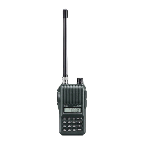
Page 8: Panel Description
PANEL DESCRIPTION ■ Front, top and side panels q PTT SWITCH [PTT] Hold down to transmit, release to receive. (p. 16) w ANTENNA CONNECTOR Connect an antenna here. (p. 1) e CONTROL DIAL [VOL] ➥ Adjust the volume level. (p. 14) ➥... - Page 9 PANEL DESCRIPTION D KEYPAD u UP/DOWN KEYS []/[] ➥ Push to change the operating channel. (p. 15) ➥ In the DTMF memory mode, push to select a DTMF memory channel. (p. 25) ➥ While scanning, push to change the scanning direction. (pp.
-
Page 10: Front, Top And Side Panels
PANEL DESCRIPTION ■ Front, top and side panels D KEYPAD (Continued) [3] • [T.SCAN](3) [9] • [H/M/L](9) ➥ Numeric input and DTMF code: ‘3’ ➥ Numeric input and DTMF code: ‘9’ ➥ After pushing [FUNC](M), starts a tone scan. ➥ After pushing [FUNC](M), selects the output (p. -
Page 11: Function Display
PANEL DESCRIPTION ■ Function display t ALPHANUMERIC DISPLAY ➥ Displays the operating channel, channel name, Set modes’ contents and a variety of other information. • The decimal point blinks during a scan. ➥ Displays the selected DTMF memory channel number. (p. 27) y BATTERY ICONS (p. -
Page 12: Battery Charging
BATTERY CHARGING ■ Caution Clean the battery terminals to avoid rust or misscontact. (for the BP-264 Ni-MH battery) Keep battery terminals clean. It’s a good idea to clean bat- R DANGER! NEVER short terminals (or charging terminals) tery terminals once a week. of the battery pack. -
Page 13: Caution (For The Bp-265 Li-Ion Battery)
If any of or dropped, or if the battery has been subjected to heavy these conditions occur, contact your Icom dealer or distributor. pressure. Battery damage may not be visible on the outside R WARNING! Immediately wash, using clean water, any part of the case. -
Page 14: D Charging Caution
CAUTION: DO NOT charge the battery outside of the speci- –20˚C to +50˚C (up to a month) fied temperature range: BC-193 (+10˚C to +40˚C). Icom rec- ommends charging the battery at +20˚C. The battery may –20˚C to +35˚C (up to three months) –20˚C to +20˚C (up to a year) -
Page 15: Battery Chargers
BATTERY CHARGING ■ Battery chargers D Using the BC-192 to regular charge the BP-264 The BC-192 regularly charges only the BP-264 Ni-MH bat- D Using the BC-191 to rapid charge the BP-264 tery pack. Never use it to charge any other battery pack. Charging time (with the 147S): Approximately 16 hours The BC-191 rapidly charges only the BP-264 Ni-MH battery pack. -
Page 16: Battery Chargers (Continued)
BATTERY CHARGING ■ Battery chargers (continued) IMPORTANT: Battery charging caution D Using the BC-193 to rapid charge the BP-265 Ensure the tabs on the battery pack are correctly aligned The BC-193 rapidly charges only the BP-265 Li-Ion battery with the guide rails inside the charger. pack. - Page 17 (OPC-656) Charger adapters* installed in each slot. There are two types of BC-197 chargers for the IC-G80; one is for Ni-MH batteries, and the other is for Li-Ion batteries. AC adapter Before you purchase a BC-197, check the type of battery you (An AC adapter is are using, and then be sure to choose the suitable charger.
-
Page 18: Battery Case (Bp-263)
BATTERY CHARGING ■ Battery case (BP-263) ■ Battery information D Battery life When using the battery case (BP-263), install 6 × AA (LR6) size alkaline batteries, as described below. Battery pack/case Voltage Capacity Battery life* q Remove the battery case, if it is attached. (p. 2) Battery case for BP-263 —*... -
Page 19: Basic Operation
BASIC OPERATION ■ Power ON/OFF ■ Adjusting the squelch level ➥ Hold down [ ] for 1 second to turn the power ON or OFF. ➥ While holding down [MONI], push [] or [] one or more times to adjust the squelch level. •... -
Page 20: Selecting An Operating Channel
BASIC OPERATION ■ Selecting an operating channel ■ Receiving D Channel selection using [] [] Make sure the BP-264 or BP-265 battery pack is fully charged, or the BP-263 battery case has brand new alkaline ➥ Push [] or [] to select a channel. batteries (pp. -
Page 21: Transmitting
BASIC OPERATION ■ Transmitting When the channel’s TX Inhibit function is pre-programmed to ON, you cannot transmit. Ask your dealer for details. CAUTION: Transmitting without an antenna will damage R WARNING! When using the BP-263 battery case, fre- the transceiver. quent or continuous transmissions can cause the batteries NOTE: To prevent interference, hold down [MONI] to listen to overheat, and may cause a burn. -
Page 22: [Vol] Function Assignment
BASIC OPERATION ■ [VOL] function assignment [VOL] and []/[] function as described below, depend- [VOL] can be used as a channel selector instead of [] and [], to suit your preference. However, when [VOL] functions as ing on the option. a channel selector, [] and [] function as volume controls. -
Page 23: Programming A Channel Name
BASIC OPERATION ■ Programming a channel name An alphanumeric name can be programmed into each chan- r Repeat step e until the channel name is programmed. nel for easy recognition. The programmed channel name is displayed instead of the channel number. Up to five charac- ters can be used for a channel name. -
Page 24: Repeater Operation
REPEATER OPERATION ■ About Repeater D Talk Around function The Talk Around function equalizes the transmit frequency To communicate with another station in a area where radio to the receive frequency for transceiver-to-transceiver com- waves cannot be directly received, you can use a repeater munication, Duplex operation temporarily changes to simplex as the relay. -
Page 25: Subaudible Tone Encoder
REPEATER OPERATION ■ Subaudible tone encoder D Tone information Some repeaters require a different tone system to be ac- Some repeaters require subaudible tones to be accessed. cessed. Subaudible tones are superimposed over your transmitted DTMF TONES signal and must be set first. While pushing [PTT], push the desired DTMF keys, [0] to [9], q Push [FUNC](M) then [SET](8) to enter the Set mode. -
Page 26: Lockout Function
REPEATER OPERATION ■ Lockout function The Lockout function helps prevent interference to other sta- tions by inhibiting transmitting when the channel is busy. The function is set in the Initial Set mode. q While holding down [] and [], turn ON the power to enter the Initial Set mode. -
Page 27: Scan Operation
SCAN OPERATION ■ Scan types ■ Channel Scan A scan automatically searches for signals, and makes it easier A channel scan repeatedly scans the operating channels, to locate new stations for contact or listening purposes. except those set as the skip channels. q Push [FUNC](M), then [SCAN](5) to start the scan. -
Page 28: Scan Resume Setting
SCAN OPERATION ■ Scan resume setting ■ Priority watch When a signal is received during a scan, the scan resume The priority watch checks for signals on the selected chan- setting determines what action the transceiver takes. The nel (Priority channel) every 5 seconds. transceiver has two scan resume settings, as described The priority channel is pre-programmed by your dealer, and below. -
Page 29: Tone Squelch And Pocket Beep
TONE SQUELCH AND POCKET BEEP ■ Tone/DTCS squelch and pocket beep D Tone squelch and DTCS squelch D Setting CTCSS tone or DTCS code q Push [FUNC](M), and then [SET](8) to enter the Set mode. The tone squelch (CTCSS) or DTCS squelch opens only when receiving a signal that includes a matching CTCSS tone or w Push [] or [] to select the CTCSS tone item (Ct) or the DTCS code, respectively. -
Page 30: Setting Dtcs Polarity
TONE SQUELCH AND POCKET BEEP D Operation ■ Tone/DTCS squelch and pocket beep (Continued) q Select an operating channel (p. 15), and then set a CTCSS D Setting DTCS polarity tone or a DTCS code (p. 24). For DTCS operation, the polarity setting is configurable, as w Push [FUNC](M), and then [TONE](1). -
Page 31: Tone Scan
TONE SQUELCH AND POCKET BEEP ■ Tone scan r When receiving a signal that includes a matching tone or By monitoring a signal from a repeater, scanning a Pocket code, the squelch opens and the signal is heard. Beep or Squelch function operation, you can determine the •... -
Page 32: Dtmf Memory
DTMF MEMORY ■ Programming a DTMF code sequence The DTMF codes are used for autopatching, controlling other r Push keys to input a DTMF code sequence of up to 24 equipment, and other operations. The transceiver has 16 digits. DTMF memory channels (d0–d9, dA, db, dC, dd, dE and dF) ... -
Page 33: Transmitting A Dtmf Code Sequence
DTMF MEMORY ■ Transmitting a DTMF code sequence D Using a DTMF memory channel The transceiver has two methods of transmitting a DTMF code sequence. Select an option in the Set mode. First, set the DTMF TX key to “dmt.m” in the Set mode. q Push [FUNC](M), and then [SET](8) to enter the Set mode. -
Page 34: Confirming A Dtmf Memory
DTMF MEMORY ■ Confirming a DTMF memory ■ Setting DTMF transfer speed The DTMF tones in a memory channel can be confirmed. When slow DTMF transmission speeds are required, the transceiver’s DTMF transmission speed can be adjusted in q Push [FUNC](M), and then [DTMF.M](0) to enter the DTMF the Initial Set mode. -
Page 35: Set Modes
SET MODES ■ Set mode programming D Set mode operation The Set mode is used to change the settings of the trans- ceiver s functions. ’ q Push [FUNC](M), and then [SET](8) to enter the Set mode. w Push [] or [] to select the item. e Rotate [VOL] to select the option or value. -
Page 36: Set Mode Items
SET MODES ■ Set mode items D DTCS Code Selects one of 104 DTCS codes for DTCS encoder and squelch. D Repeater tone frequency (Encoder) • 023–754 Selects one of 50 subaudible tone frequencies used only to access the repeaters. •... -
Page 37: Lcd Backlight
SET MODES D Scan resume setting D LCD backlight Selects the scan resume setting between SCt. 5, SCt. 10, Selects the LCD Backlight function. SCt. 15, and SCP. 2. • LIG.OF : Turns OFF the Backlight function. When a signal is received during a scan, the scan pauses •... -
Page 38: Microphone Gain
SET MODES D Microphone gain Sets the microphone gain to between 1 and 4 to suit your needs. Higher values make the microphone more sensitive to your voice. The VOX Time-out Timer must be set shorter than the Time-out Timer, otherwise this timer will not function. D DTMF TX key Selects the method to transmit a DTMF code sequence. -
Page 39: Initial Set Mode Programming
SET MODES ■ Initial Set mode programming D Initial Set mode operation The Initial Set mode can be accessed at power ON and al- lows you to set seldom-changed settings, to suit your prefer- q While holding down [] and [], turn ON the power to ence and operating style. -
Page 40: Initial Set Mode Items
SET MODES ■ Initial Set mode items D Key-touch beep D Auto power-OFF Turns the key-touch beep ON (the beep level 1 to 3) or OFF. The transceiver can automatically turn itself OFF after a • When changing the beep level, beeps sound at the level. specified time. -
Page 41: Squelch Delay
SET MODES D Squelch delay D [VOL] function assignment Sets the squelch delay between short and long. The delay Selects whether or not to use [VOL] as the selector channel instead of [] and []. When [VOL] functions as the prevents the squelch from repeatedly opening and closing channel while continuously receiving a weak signal. -
Page 42: Lcd Contrast
SET MODES D LCD Contrast D Dial Acceleration Selects the LCD contrast. Selects whether or not to accelerate the changing speed when rotating [VOL] rapidly. • Lcd.LO : Sets the contrast to low. • Lcd.At : Sets the contrast to high. However, if the transceiver is •... - Page 43 SET MODES • User remote control unit D Battery protection The circuit illustrated below is for reference only. When the battery voltage decreases, the Battery Protection to the [SP] jack function automatically turns OFF the transceiver. REMOTE Select the function option according to your battery type. 3.5(d) mm 2.7 kΩ...
-
Page 44: Trouble Shooting
TROUBLE SHOOTING If your transceiver seems to be malfunctioning, please check the following points before sending it to a service center. PROBLEM POSSIBLE CAUSE SOLUTION REF. The transceiver does not turn • The battery is exhausted. • Charge the battery pack, or replace the batteries. pp. -
Page 45: Options
After connecting, the VOX function AC adapter may be supplied with the charger, depending on the can be used. version. There are two types of BC-197 chargers for the IC-G80. Approved Icom optional equipment is designed for optimal BC-197 Charger Type... -
Page 46: Vox Function
OPTIONS ■ VOX function D Turning the VOX function ON or OFF The transceiver has a VOX function, which allows hands-free operation. q Connect an optional headset and plug adapter cable to An optional HS-94, HS-95 or HS-97 headset and the OPC- the transceiver, and then turn ON the power. - Page 47 OPTIONS D VOX-related settings “On” is intermittent, be sure the VOX delay is set long enough to allow normal pauses in speech, but keep the The VOX gain, the VOX delay, and the VOX Time-out Timer VOX ON until you finish speaking. is set in the Set mode.
- Page 48 A-6867D-1EX Printed in Japan 1-1-32 Kamiminami, Hirano-ku, Osaka 547-0003, Japan © 2010 Icom Inc. Printed on recycled paper with soy ink.
Need help?
Do you have a question about the IC-G80 and is the answer not in the manual?
Questions and answers