Table of Contents
Advertisement
Quick Links
Advertisement
Table of Contents

Subscribe to Our Youtube Channel
Related Manuals for Icom IC-GM800


Summary of Contents for Icom IC-GM800
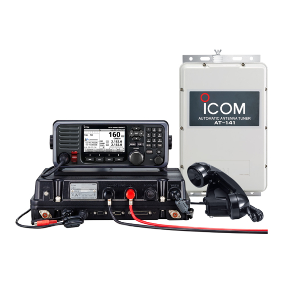
- Page 1 INSTRUCTION MANUAL MF/HF MARINE TRANSCEIVER GM800...
- Page 2 The GM800 is designed hf marine transceiver and built with Icom’s state of the art technology and craftsmanship. With proper care, this product should provide you with years of trouble-free operation. The GM800 has Class A DSC functions for Distress...
- Page 3 L The connectors on the rear panel do not meet IPX7. been dropped. Contact your Icom distributor or your dealer for advice.
- Page 4 2.0 meters of the antenna, nor operated at all if any person is touching the antenna. It is recommended that antenna of a maximum gain of 0 dBd is used. If higher gain antenna are required then please contact your Icom distributor for revised installation recommendations. Operation: The exposure to RF electromagnetic field is only applicable when this device is transmitting.
-
Page 5: Table Of Contents
TABLE OF CONTENTS 1. OPERATING RULES ....1 D Assigning a Software Key D Receiving a Ships and Aircraft call . 68 function to [P] on the HM-214H ■ Received Call log ......69 2. PANEL DESCRIPTION ..2–7 ������������������������������� 22 D Distress message ...... 69 microphone ■... -
Page 6: Operating Rules
OPERATING RULES NOTE: Before transmitting, monitor the channel you want to use to avoid interrupting communications already in progress. • CALL PROCEDURE • RADIO LICENSES Calls must be properly identified and the time limit (1) SHIP RADIO STATION LICENSE must be respected. You need a current ship radio station license before using the transceiver. -
Page 7: Panel Description
PANEL DESCRIPTION ■ Matn unta FERRITE EMI FILTER FERRITE EMI FILTER q GROUND TERMINAL [GND] y MODEM SOCKET [AF/MOD] (p. 87) Connect to the ship’s ground. (p. 81) Connect to an external terminal unit for SSB mode operation through an RS-232C cable w DSC ANTENNA CONNECTER (D-sub 15-pin). -
Page 8: Remote Controller Front Panel
PANEL DESCRIPTION ■ Remote Controller front panel SPEAKER FUNCTION DISPLAY (p. 6) MIC CONNECTOR SOFTWARE KEYS (p. 4) q DISTRESS KEY [DISTRESS] VOLUME DIAL [VOL] Hold down for 3 seconds to transmit a Distress Rotate to adjust the speaker volume level. ... -
Page 9: Handset
PANEL DESCRIPTION ■ Handsea ■ Software Key function The transceiver has Software Keys for various D About the Speaker Switch functions. The key's function is displayed above When the switch is set to the “ ” position: them, as shown below. You can hear the receive audio from the remote controller's speaker. -
Page 10: D Functions
PANEL DESCRIPTION ■ Software Key function D Functions SP × You can use various Software Key functions that are assigned to the Software Keys, as described below. Push to turn the speaker output ON or OFF. Compose Distress AGC × Push to compose a Distress call. -
Page 11: Function Display (Main Screen)
PANEL DESCRIPTION ■ Function display (Matn scoeen) r Channel and q Status area Display area Description Frequency area w Task area e Information area q Saaaus aoea Displays the current status. w Task aoea Displays up to 7 task icons. e Innooraaton Displays various icons and the aoea... -
Page 12: D Position Date And Time Area
PANEL DESCRIPTION ■ Function display (Main screen) D Position Date and Time area POSITION AREA DATE AND TIME AREA The current position is displayed when valid GPS • The current time is displayed when valid GPS data data is received, or when you manually enter your is received, or manually enter the time. -
Page 13: Preparation
PREPARATION ■ Entering the MMSI code First, you must enter your 9 digit MMSI (Maritime 5. Reenter your MMSI code to confirm. Mobile Service Identity: DSC self ID) code at power Push You can perform this initial code entry ONLY ONCE. -
Page 14: Menu Screen
MENU SCREEN You can use the Menu screen to set infrequently changed values or function settings. ■ Menu Construction The Menu screen is constructed in a tree structure. To select an item, rotate [CH/GRP]. You can go to the next tree level by pushing [ENT], or go back a level by pushing [CLR]. -
Page 15: Selecting The Item
MENU SCREEN ■ Selecting the item Follow the procedures described below to select a Innooraaton Menu item. You can use the following key functions in the MENU screen. Example: Turning ON the Voice Squelch function. FUNCTION ACTION Select Rotate [CH/GRP], or 1. -
Page 16: Basic Operation
BASIC OPERATION ■ Selecting a Channel oo Group D Using the channel and gooup selectoo [ENT] 1. Push [CH/GRP] to toggle the Channel Select mode or the Group Select mode. • “ ” or “ ” is displayed. KEY PAD 2. -
Page 17: Receiving And Transmitting
BASIC OPERATION ■ Receiving and toansmitting D Receiving [Ω]/[≈] 1. Select a channel by rotating [CH/GRP], or pushing the keypad keys. (p. 11) KEY PAD 2. When receiving a call, rotate [VOL] to adjust the audio output level. TIP: When a call is received: •... -
Page 18: Other Functions And Operations
OTHER FUNCTIONS AND OPERATIONS ■ Backlight function The function display and keys can be backlit for better visibility under low light conditions. You can set the Backlight mode to Day mode or Night mode. The Day mode is for the daytime operation, and the screen items are in color. -
Page 19: Scan
OTHER FUNCTIONS AND OPERATIONS ■ Scan The transceiver has automatic channel or frequency Select a scan type in the Menu screen. scan capabilities (Scan function). There are 3 types See page 76 for details. of scan functions. • Channel scan •... -
Page 20: Other Functions
OTHER FUNCTIONS AND OPERATIONS ■ Otheo functions D Toansmit Foequency Monitoo function When selecting a duplex channel, the transmit 1. Push [Ω] or [≈] until “TX FREQ Monitor” is frequency differs from the receive frequency. displayed in the Software Key area. To prevent from interference to other stations, the 2. -
Page 21: D Automatic Gain Control Off
OTHER FUNCTIONS AND OPERATIONS D Automatic Gain Control OFF The Automatic Gain Control (AGC) function 1. Push [Ω] or [≈] until “AGC ×” is displayed in the prevents distortion from strong signals and Software Key area. maintains a constant output level. 2. -
Page 22: Setting A Temporary Operating Frequency
OTHER FUNCTIONS AND OPERATIONS ■ Setting a tempooaoy opeoating foequency You can temporarily change the operating frequency 5. Enter a TX frequency, then push [ENT]. of the selected channel. The frequency returns to the Push preset value after you select another channel, or turn OFF the transceiver. -
Page 23: Setting A User Channel Or An Itu Simplex Channel
OTHER FUNCTIONS AND OPERATIONS ■ Setting a Useo channel oo an ITU Simplex channel Your dealer has already preset User channels and NOTE: ITU Simplex channels. • If you edit the preset channels, you may not be able to Follow the instructions as described below, only when communicate with other ships. - Page 24 OTHER FUNCTIONS AND OPERATIONS ■ Setting a User channel or an ITU Simplex channel 4. Setting a channel name 2. Setting an RX and TX operating frequencies (continued) You can set a channel name of up to 10 characters 8. Enter a TX frequency. for each User and ITU channel.
-
Page 25: Assigning A Function
OTHER FUNCTIONS AND OPERATIONS ■ Assigning a function You can assign some different Software Key functions to a key between Soft Key 5 and Soft Key 20. (p. 5) You can also assign some Software Key functions to [VOL] on the controller and [P] on the optional HM-214H �... -
Page 26: D Assigning A Software Key Function To [Vol]
OTHER FUNCTIONS AND OPERATIONS ■ Assigning a function D Assigning a Softwaoe Key function to [VOL] Example: Assigning “Backlight” to “Push ×3.” 6. Select a Software Key function. 1. Push [MENU]. (Example: Backlight) 2. Select “Configuration.” Rotate Rotate CH/GRP CH/GRP Push Push •... -
Page 27: Microphone
OTHER FUNCTIONS AND OPERATIONS D Assigning a Softwaoe Key function to [P] on the HM-214H MICROPHONE Example: Assigning “Mode” to [P]. 5. Select a Software Key function. (Example: Mode) 1. Push [MENU]. 2. Select “Configuration.” Rotate Rotate CH/GRP CH/GRP Push Push •... -
Page 28: Dsc Operation
DSC OPERATION ■ DSC mdress ID You can enter a total of 100 DSC address IDs, and TIP: You can use the following key operations in the assign a name of up to 10 characters to each ID. Menu screen. Inffrrmaifn ACTION OPERATION... - Page 29 DSC OPERATION 8. Enter an RX frequency. 12. Push [Save] After entering, push [▲], [▼], [◄], or [►] to select “Done” and push [ENT]. Push Rotate CH/GRP Push to select a character 13. Push [OK] to save the ID. 9. Enter a TX frequency. After entering, push [▲], [▼], [◄], or [►] to select “Done”...
-
Page 30: Dsc Adress Id
DSC OPERATION ■ DSC adress ID D Enaering m Grfup ID 1. Push [MENU]. 6. Enter a 9 digit Group ID. 2. Select “DSC Settings.” After entering, push [▲], [▼], [◄], or [►] to select “Done” and push [ENT]. Rotate Push CH/GRP Push... -
Page 31: D Deleting An Entered Id
DSC OPERATION 10. Select “Name.” D Deleaing mn enaered ID 1. Push [MENU]. Rotate • “MENU” screen is displayed. 2. Rotate [CH/GRP] to select “DSC Settings.” CH/GRP • “DSC SETTING” screen is displayed. 3. Select “Individual ID” or “Group ID.” Push •... -
Page 32: Entering Position Data And Time
DSC OPERATION ■ Enaering pfsiaifn dmam mnd aire A Distress call should include the ship’s position data and time. If a GPS receiver compatible with the IEC61162-1 Ed.4 (2010-11) format is connected, Push position and UTC time are automatically included. If no GPS is connected, you should manually enter your Set ‘N’... - Page 33 DSC OPERATION 8. Enter your UTC time. TIP: When position data and time are set, Latitude, Push Longitude and UTC Time are displayed. Enter Rotate CH/GRP to select a character Rotate • Latitude: 34°37.1093N • Longitude: 135°34.2913E Cursor moves CH/GRP •...
-
Page 34: Dsc Task Mode
DSC OPERATION ■ DSC Tmsk rfde • Hold window After sending or receiving the DSC call, the transceiver enters the DSC Task mode. L To view the contents, push [Ù] or [Ú]. (Example: After receiving a Geographical call) D Software Key functions While in the DSC Task mode, the following functions In the DSC Task mode, you can resend the call, or are displayed first. -
Page 35: Sending A Distress Call
DSC OPERATION ■ Sending a Distress call NOTE: NEVER make a Distress call if your ship or a person is not in an emergency. A Distress call should be made only when immediate help is needed. You should send a Distress call if, in the opinion of the Master, the ship or a person is in distress and requires immediate assistance. -
Page 36: D Regular Call
DSC OPERATION ■ Sending a Distress call D Regular call Step 3. Setting a communication frequency 1. Push [Compose Distress] to display the COMPOSE DISTRESS screen. 6. Select “Attempt.” Rotate CH/GRP Push Push 7. Select an option. (Example: Multi Frequency) Step.1 Setting a “Nature of Distress”... - Page 37 DSC OPERATION NOTE: To cancel a Distress call while NOTE: transmitting see page 34. Transmitting: • A Distress call default contains: 9. After sending, the following screen is displayed. - Nature of distress: Undesignated distress - Position data: The latest GPS or manual input position data is retained for 23.5 hours, unless you turn OFF the transceiver.
-
Page 38: D Resending A Distress Call
DSC OPERATION ■ Sending a Distress call D Resending a Distress call While waiting for an acknowledgement, you can 3. When receiving the acknowledgement: resend the call (Repeat call). • Alarms sound. • The following screen is displayed. Push any [Alarm Off] 1. -
Page 39: D Sending A Distress Cancel Call
DSC OPERATION D Sending a Distress Cancel call 3. After sending, the following screen is displayed. You can send the Distress Cancel call while Push [Select FREQ] transmitting a Distress call or while waiting for a Distress Acknowledgement. While transmitting a Distress call: 1. - Page 40 DSC OPERATION ■ Sending a Distress call D Sending a Distress Cancel call (continued) 4. Select a frequency to send a voice cancel message and push [ENT]. While waiting for a Distress Acknowledgement: The check mark shows that the Distress call on the selected frequency is canceled by sending voice 1.
-
Page 41: D Sending A Distress Acknowledgement
DSC OPERATION D Sending a Distress acknowledgement Distress call reception should stop after one 4. Push [ACK (Distress)] sequence because the coast station should send back an ‘acknowledgement’ to the ship. If the distress call continues even the coast station send back an ‘acknowledgement,’... -
Page 42: D Sending A Distress Relay Call
DSC OPERATION ■ Sending a Distress call D Sending a Distress Relay call D Sending a Distress acknowledgement (continued) 7. After sending, the following screen is displayed. There are 2 ways to transmit the distress relay call— “DROBOSE (Distress Relay On Behalf Of Someone Else)”... - Page 43 DSC OPERATION 3. Select a message type. 7. Select “Manual Input.” (Example: Individual) Rotate Rotate CH/GRP CH/GRP Push Push NOTE: Distress Call Log is displayed after receiving 4. Select “Address.” DO NOT the Distress call. select displayed Individual IDs for DROBOSE. Rotate 8.
- Page 44 DSC OPERATION ■ Sending a Distress call D Sending a Distress Relay call (continued) 15. Push [Call] to send the Distress Relay call. 11. Select “Position.” Rotate CH/GRP Push Push • The Latitude Position Entry screen is displayed. • Your position data and time are displayed. 12.
- Page 45 DSC OPERATION To transmit the Distress Relay call with 4. Select “Address.” “Distress Call Log”: Rotate You can relay a distress call after receiving the distress call. CH/GRP Push Distress Relay Transmission Coast Station 5. Select a coast station address or “Manual Input.” Your ship (Example: COAST A) Distress Transmission...
- Page 46 DSC OPERATION ■ Sending a Distress call D Sending a Distress Relay call (continued) 11. After sending, the following screen is displayed. 8. Select “Call Frequency.” Rotate CH/GRP Push See page 29 for details of the software key function in the DSC Task mode.
-
Page 47: D Sending A Distress Relay Acknowledgement
DSC OPERATION D Sending a Distress Relay acknowledgement Only when the Distress Relay call is received, you 5. Push [Call] to send the Distress Relay can send the Distress Relay acknowledgement. acknowledgement. Quick ACK: 1. When a Distress Relay call is received: •... -
Page 48: Sending A Non-Distress Calls
DSC OPERATION ■ Sending a Non-Distress calls D Sending an Individual call The Individual call function enables you to transmit 4. Select “Category.” a DSC signal to only a specifi c coast station or ship. Rotate After transmission, wait for an acknowledgement from the receiving station. - Page 49 DSC OPERATION 6. Select “Comm Frequency.” 10. When receiving the acknowledgement: • Alarm sounds. Rotate • The following window is displayed. (Example: ACK (Able)) CH/GRP Push any [Alarm Off] Push 7. Select a communication frequency, or “Manual Input.” (Example: SHIP 2M) Rotate 11.
-
Page 50: D Sending An Individual Acknowledgement
DSC OPERATION ■ Sending a Non-Distress calls D Sending an Individual acknowledgement When receiving an Individual call, you can send an 5. Rotate [CH/GRP] to confirm the contents. acknowledgement (‘Able,’ ‘Unable,’ or ‘New CH’) by 6. Push [Call] to send the Individual using the on-screen prompts. - Page 51 DSC OPERATION 5. Select a Group ID, or “Manual Input.” 7. Select a communication frequency, or “Manual (Example: GROUP 1) Input.” (Example: SHIP 2M) Rotate Rotate CH/GRP CH/GRP Push Push NOTE: When you select “Manual Input” in this step, NOTE: When you select “Manual Input” in this push the keypad to manually enter a Group ID.
-
Page 52: D Sending A Geographical Call
DSC OPERATION ■ Sending a Non-Distress calls D Sending a Geographical call Send a Geographical call when urgency or safety 5. Select “Circle” or “Quadrant.” message announcement is necessary to the ships in Rotate the particular area. CH/GRP 1. Push [Compose Non-Distress] Push 6. - Page 53 DSC OPERATION Enter the radius of the Geographical call area. Enter the height of the Geographical call area. After entering, select “Done” and push [ENT]. After entering, select “Done” and push [ENT]. (Example: 500 nm) Push Push Rotate Rotate CH/GRP CH/GRP to select a character...
- Page 54 DSC OPERATION ■ Sending a Non-Distress calls D Sending a Geographical call (continued) 9. Select “Call Frequency.” 13. Push [Call] to send the Geographical call. Rotate CH/GRP Push Push 10. Select an option. (Example: 8414.5 kHz) 14. After sending, the following screen is displayed. Rotate ...
-
Page 55: D Sending A Position Request Call
DSC OPERATION D Sending a Position Request call Send a Position Request call when you want to know 5. Select an Individual ID, or “Manual Input.” a specifi c ship’s current position, and so on. (Example: STATION A) Rotate 1. Push [Compose Non-Distress] CH/GRP Push NOTE:... -
Page 56: D Sending A Position Request Acknowledgement
DSC OPERATION ■ Sending a Non-Distress calls D Sending a Position Request call (continued) 9. After sending, the following screen is displayed. 4. Push a key to select an acknowledgement option. • See page 29 for details of the software key function (Example: ACK (Able)) in the DSC Task mode. -
Page 57: D Sending A Polling Request Acknowledgement
DSC OPERATION D Sending a Polling Request acknowledgement When a Polling Request is received, you can send an 5. Push [Call] to send the Polling Request acknowledgement. acknowledgement. 1. When a Polling Request call is received: • Alarm sounds. • The following screen is displayed. Push any [Alarm Off] Push •... -
Page 58: D Sending A Test Call Acknowledgement
DSC OPERATION ■ Sending a Non-Distress calls D Sending a Test call (continued) 8. Push [Call] to send the Test call. 3. Select “Test.” Rotate CH/GRP Push Push 4. Select “Address.” 9. After sending, the following screen is displayed. See page 29 for details of the software key function Rotate in the DSC Task mode. -
Page 59: D Sending A Medical Transports Call Or Ships And Aircraft Call
DSC OPERATION D Sending a Medical Transports call or 2. Push [Accept] Ships and Aircraft call The Medical Transports call informs all ships, by urgency priority, that your ship is carrying a patient in need of medical treatment. The Ships and Aircraft call informs all ships that your ship is a neutral (not a participant) in armed confl... - Page 60 DSC OPERATION ■ Sending a Non-Distress calls D Sending a Medical Transports call or Ships and 2 Enter the longitude of your position. Aircraft call (continued) After entering, select “Done” and push [ENT]. Displays your ship's position as default. 4.
- Page 61 DSC OPERATION 9. Select “Comm Frequency.” Enter the longitude of your position. After entering, select “Done” and push [ENT]. Rotate Push CH/GRP Push Rotate CH/GRP to select a character 10. Select a communication frequency, or “Manual Enter the height of the Medical Transports call Input.”...
-
Page 62: Receiving Dsc Calls
DSC OPERATION ■ Receiving DSC calls NOTE: After receiving a DSC call • “ ” is continuously displayed when the transceiver has DSC calls. • “ ” continuously blinks when the transceiver has an unread DSC message in the Received Call Log. -
Page 63: D Receiving A Distress Acknowledgement
DSC OPERATION D Receiving a Distress acknfwledgerent 8. Select your desired Individual ID, or “Manual Input.” (Example: STATION A) 1. When a Distress Acknowledgement is received: • Alarm sounds. Rotate • The following screen is displayed and the backlight blinks. CH/GRP •... -
Page 64: D Receiving A Distress Cancel Call
DSC OPERATION ■ Receiving DSC calls D Receiving a Distress Cancel call TIP: When you push [Pause] in step 2, the countdown will be paused. Push [Resume] 1. When a Distress Cancel call is received: restart the countdown. • Alarm sounds. •... -
Page 65: D Receiving A Distress Relay
DSC OPERATION D Receiving a Distress Relay acknfwledgerent 1. When a Distress Relay Acknowledgement is received: • Alarm sounds. • “ ” is displayed. • The following screen is displayed and the backlight blinks. Push [Alarm Off] Inffrratifn • The communication frequency is automatically selected. -
Page 66: D Receiving An Individual Call
DSC OPERATION ■ Receiving DSC calls D Receiving an Individual call NOTE: When the “Individual ACK” item is set to Auto, the transceiver automatically sends an acknowledgement. In that case, both the TX and RX calls are stored in the Transmitted and Received Call Logs. - Page 67 DSC OPERATION When receiving “ACK (able)”: When receiving “ACK (unable)”: You can make the voice communication on the You cannot make the voice communication. frequency that you specified when you sent the call. 1. When an Individual acknowledgement “ACK 1. When an Individual acknowledgement “ACK (unable)”...
-
Page 68: D Receiving A Group Call
DSC OPERATION ■ Receiving DSC calls D Receiving a Grfup call D Receiving an Individual acknowledgement (continued) NOTE: To receive a Group call, push [D-SCAN] to When receiving “ACK (New CH)”: enter the DSC watch mode. 1. When an Individual acknowledgement “ACK (New CH)”... -
Page 69: D Receiving A Geographical Area Call
DSC OPERATION 2. Select your desired action. [Hold]: Push [Hold] to return to the Main screen. Inffrratifn [Pause]: Push [Pause] to pause the • Monitors the communication frequency specified by countdown. the calling station for an announcement from the [Accept]: Push [Accept] to enter the DSC calling station. -
Page 70: D Receiving A Position Request Call
DSC OPERATION ■ Receiving DSC calls D Receiving a Pfsitifn Request call D Receiving a Pfsitifn Request acknfwledgerent NOTE: When “Position ACK” is set to “Auto,” the transceiver automatically replies to the call. In that 1. When a Position Request acknowledgement is case, both the TX and RX calls are stored in the received: Transmitted and Received Call Logs. -
Page 71: D Receiving A Polling Request Call
DSC OPERATION D Receiving a Pflling Request call D Receiving a Test call NOTE: When “Polling ACK” is set to “Auto,” the NOTE: When “Test ACK” is set to “Auto,” the transceiver automatically replies to the call. In that transceiver automatically replies to the call. In that case, both the TX and RX calls are stored in the case, both the TX and RX calls are stored in the Transmitted and Received Call Logs. -
Page 72: D Receiving A Test Acknowledgement
DSC OPERATION ■ Receiving DSC calls D Receiving a Test acknfwledgerent D Receiving a Medical Transpfrts call 1. When a Test acknowledgement is received: 1. When a Medical Transports call is received: • Alarm sounds. • Alarm sounds. • The following screen is displayed and the backlight •... -
Page 73: D Receiving A Ships And Aircraft Call
DSC OPERATION TIP: When you push [Pause] in step 2, the countdown will be paused. Push [Resume] restart the countdown. Inffrratifn • Monitors the communication frequency specified by the calling station for an announcement from the calling station. • Rotate [CH/GRP] to confirm the call contents. •... -
Page 74: Received Call Log
DSC OPERATION ■ Received Call lfg The transceiver automatically stores up to 50 distress NOTE: messages and 50 other messages, and they can be • When there is an unread DSC message, “ ” blinks on used as a supplement to your logbook. the information area of the LCD. -
Page 75: Dsc Settings
DSC OPERATION ■ DSC Settings D Position Input (See page 27) D Individual ID (See page 23) D Group ID (See page 25) D DSC Frequency 6. Select an option. (Example: Call) This set frequencies are selectable when you want to Rotate send an Individual call, Group call, Geographical Area call, Position Request call, or Test call. -
Page 76: D Automatic Acknowledgement
DSC OPERATION ■ DSC Settings D Automatic acknowledgement D DSC Frequency (Continued) These items set the Automatic Acknowledgement 10. Select “Name.” function. When you receive an Individual call, Position Request call, Polling Request call or Test Rotate call, the transceiver automatically sends each acknowledgement, if “Auto”... -
Page 77: D Setting The "Medical Transports" Item Display Option
DSC OPERATION D Setting the “Medical Transports” item D Distress Scanning Receiver display option You can turn the Distress Scanning Receiver function ON or OFF on each Emergency frequency. You can select whether or not the “Medical Transports” item is displayed in the COMPOSE NON- NOTE: You cannot turn OFF the function on DISTRESS screen. -
Page 78: D Setting The 10 Second Delay
DSC OPERATION ■ DSC Settings D Setting the 10 Second Delay D Setting the Alarm Status Safety/Routine Select whether or not the transceiver automatically switches to the displayed frequency 10 seconds after Select whether or not to sound an alarm when receiving a DSC call. -
Page 79: D Auto Print
DSC OPERATION D Auto Print Select whether or not to enable the Automatic Print Self-Terminate Out function when a DSC call is received. Select whether or not to sound an alarm when The received DSC call content is printed out if a receiving the same Distress call. -
Page 80: Menu Items
MENU ITEMS ■ Menu items D Compose Non-Distress • Individual calls (p. 43) The Menu screen is constructed in a tree structure. • Group calls (p. 45) (p. 9) • Geographical calls (p. 47) • Position Request calls (p. 50) •... -
Page 81: Configuration
MENU ITEMS ■ Configuration D Key Beep D UTC Offset Turn the Key Beep function ON or OFF. Set the offset time between UTC (Universal Time • On: When you push a key, a beep sounds. (Default) Coordinated) and your local time to between –14:00 •... - Page 82 MENU ITEMS Not DSC Related • For RT Related (except J3E): (Configuration > Inactivity Timer > Not DSC Related) Set the inactivity timer 10 sec, 30 sec, between 1 and The transceiver automatically returns to the Main 10 min (in 1 minute steps), or OFF. screen if you push no key for this set time period.
-
Page 83: Connections And Installation
DC power terminals. It keeps its temperature to at a specifi ed level, even if you turn OFF the power by holding down [ ] on the remote controller. GM800 NOTE: Must be used with the ICOM AT-141. Rubber vulcanizing tape... -
Page 84: Advanced Connections
CONNECTIONS AND INSTALLATION ■ Basic connections HF antenna SP-24E (for DSC reception) ( Purchase 24 V separately) Ferrite EMI filter battery (p. 82) [DC ISOLATE] Ground (p. 81) GM800 main unit Ground (p. 81) AT-141 Remote controller HS-98 ■ Advanced connections •... -
Page 85: Ground Connection
Wide Copper strap Copper pipe Metal object Copper screen ■ Software maintenance The Icom customer support center provides the fi rmware fi le for transceiver maintenance. You can update the transceiver’s fi rmware through a PC. To the [MAINTENANCE] OPC-478UC... -
Page 86: Power Source
CONNECTIONS AND INSTALLATION ■ Power source • Attaching the weatherproof cap The transceiver requires a regulated DC power source of 26.4 V and at least 30 A. Attach the supplied weatherproof cap for each Connect a transceiver directly to a 24 V battery in positive and negative line at the DC power terminal your ship using the supplied DC power cable. -
Page 87: Mounting
CONNECTIONS AND INSTALLATION ■ Mounting D Mounting location D Attaching the mounting plates Select a location that provides easy access to the 1. Attach the supplied rubber feet to the mounting remote controller for navigation safety, has good plate, if desired. ventilation and is not exposed to sea spray. -
Page 88: Using The Optional Mb-108
CONNECTIONS AND INSTALLATION ■ Using the optional MB-108 The optional MB-108 mounting bracket can be used CAUTION: Wear gloves when installing the to mount the transceiver’s main unit. The MB-108. The edges of the MB-108 may be sharp MB-108 provides one-touch attachment or and may easily cut your fingers or hands. -
Page 89: Replacing Fuses
CONNECTIONS AND INSTALLATION ■ Replacing fuses The transceiver has 2 fuses to protect internal CAUTION: Disconnect the DC power cable from the circuitry. transceiver before replacing a fuse. If the transceiver stops functioning, and only after confirming a fuse is probably blown, check the fuses below. -
Page 90: Connector Information
CONNECTIONS AND INSTALLATION ■ Connector information MICROPHONE Pin name Description Specification MIC (+) Audio input from the mic element. Input impedance: 2.4 kΩ MIC SW Key detection. – AF output controlled by [VOL]. – Ground for AF1. – PTT switch input. –... -
Page 91: Transceiver Dimensions
CONNECTIONS AND INSTALLATION PRINTER Pin name Description STROBE Outputs a strobe pulse after data output. DATA1~8 Outputs 8 bit parallel data. Receives a ‘Low’ pulse from the printer when the printer can accept more ACKNLG data. 13......1 The printer sets this pin to ‘High’ when it can not accept data, such as BUSY when the printer is ‘off line.’... -
Page 92: Specifications And Options
SPECIFICATIONS AND OPTIONS ■ Specifications D General D Transmitter • Frequency coverage: • Output power: 0.5 ~ 29.9999 MHz At radio terminal 150 W PEP into 50 Ω 1.6 ~ 2.9999 MHz, 4.0 ~ 4.9999 MHz At tuner output 1.6~3.9999 MHz 85 W PEP 6.0 ~ 6.9999 MHz, 8.0 ~ 8.9999 MHz 4.0~27.5000 MHz 125 W PEP 12.0 ~ 13.9999 MHz, 16.0 ~ 17.9999 MHz... - Page 93 SPECIFICATIONS AND OPTIONS ■ Options The following items are sold as a set with the GM800. AT-141 U-bolts U-bolt brackets 4-pin connector Flat washers Flat washers Spring washers Nuts (M6 small) (M6 large) (M6) (M6) Rubber vulcanizing Hex head blots Self-tapping screws Weatherproof cap tape...
-
Page 94: Troubleshooting
TROUBLESHOOTING PROBLEM POSSIBLE CAUSE SOLUTION REF. The transceiver does • Bad connection to the power • Check the connection to the p. 80 not turn ON. supply. transceiver and power supply. • Fuse is blown. • Find the cause, repair, then p. -
Page 95: Digital Interface (Iec 61162-1)
DIGITAL INTERFACE (IEC 61162-1) ■ I/O Sentences D Version number IEC61162-1 Ed.4(2010-11) D GPS Input sentences (IEC 61162-1) GGA, GLL, GNS, and RMC D GPS Input sentence description • GGA—Global positioning system (GPS) fix data $--GGA,hhmmss.ss,llll.ll,a,yyyyy.yy,a,x,xx,x.x,x.x,M,x.x,M,x.x,xxxx*hh<CR><LF> 5 6 7 8 9 10 11 12 13 14 UTC of position (000000.00 to 235959.99) Horizontal dilution of precision (no use) Latitude (0000.0000 to 9000.0000) -
Page 96: D Remote Input And Out Putsentences (Iec 61162-1)
DIGITAL INTERFACE (IEC 61162-1) ■ I/O Sentences D Remote Input and Output sentences (IEC 61162-1) Input: FSI (Set or Query), Output: FSI (Query receive), DSC (DSC receive), DSE (DSC receive) D Remote sentence description • FSI—Frequency set status or command $--FSI,xxxxxx,xxxxxx,c,x,a*hh<CR><LF>... -
Page 97: Schematic Diagram
DIGITAL INTERFACE (IEC 61162-1) ■ Schematic diagram C9103 0.01 IC9101 D9102 NMEI2 L1SS400 IC9054 R9101 Q9057 TC7W08FU 2SC4116 GPS+ PC357N6J000F R9106 C9102 GPS- 0.0047 H3R3V S13V R9057 Q9051 Q9055 R9063 2SC4116 R9058 2SC4116 R3915 C9058 0.01 R3916 J9051 L9154 C9057 L9153 100U IC9051... -
Page 98: Hardware Version
DIGITAL INTERFACE (IEC 61162-1) ■ Hardware version The transceiverʼs hardware version is described on the serial number label, as shown to the right. Hardware version ■ Software version You can confi rm the transceiverʼs software version in the Menu screen. 1. -
Page 99: Index
INDEX Position Request call Accessories ........78 Group Sending...........50 AGC ...........16 Selecting .........11 Group call Position Request Call Antenna ..........81 Receiving ........63 Receiving ........65 AT-141 ..........81 Automatic acknowledgement.....71 Sending...........45 Power source........81 Automatic Antenna Tuner function..16 Group ID Precautions.......... ii Automatic Gain Control OFF .....16 Deleting...........26 Reassigning Backlight ..........13... - Page 100 A7258H-1EU-2 Printed in Japan 1-1-32 Kamiminami, Hirano-ku, Osaka 547-0003, Japan © 2018–2019 Icom Inc. Apr. 2019...
Need help?
Do you have a question about the IC-GM800 and is the answer not in the manual?
Questions and answers