AudioCodes MediaPack MP-124 User Manual
Mediapack mp-11 series cpe & access analog gateways
Hide thumbs
Also See for MediaPack MP-124:
- User manual (504 pages) ,
- Installation manual (58 pages) ,
- Fast track manual (44 pages)
Table of Contents
Advertisement
Quick Links
Advertisement
Table of Contents

Related Manuals for AudioCodes MediaPack MP-124


Summary of Contents for AudioCodes MediaPack MP-124
- Page 1 User's Manual Version 5.6 Document #: LTRT-65411 November 2008...
-
Page 3: Table Of Contents
SIP User's Manual Contents Table of Contents Overview ......................15 1.1 Gateway Description ....................15 1.2 MediaPack Features ....................16 1.2.1 MP-11x Hardware Features ..................16 1.2.2 MP-124 Hardware Features ..................17 1.3 SIP Overview ......................17 ... - Page 4 MediaPack Series 3.4.2 Media Settings ......................67 3.4.2.1 Configuring the Voice Settings ..............67 3.4.2.2 Configuring the Fax / Modem / CID Settings ........... 70 3.4.2.3 Configuring the RTP / RTCP Settings ............. 74 ...
- Page 5 SIP User's Manual Contents 4.2.4 Example of an ini File .................... 235 4.3 Modifying an ini File ....................235 4.4 Reference for ini File Parameters ................. 236 4.4.1 Networking Parameters ..................236 4.4.2 System Parameters....................244 ...
- Page 6 MediaPack Series 7.4.1.3 Call Termination (Disconnect Supervision) on FXO Devices ....328 7.4.1.4 DID Wink ....................329 7.4.2 Telephone-to-IP Calls ................... 330 7.4.2.1 Automatic Dialing ................... 330 7.4.2.2 Collecting Digits Mode ................330 ...
- Page 7 SIP User's Manual Contents 8.7 IP QoS via Differentiated Services (DiffServ) ............369 8.8 VLANS and Multiple IPs ..................370 8.8.1 Multiple IPs ......................370 8.8.2 IEEE 802.1p/Q (VLANs and Priority) ..............370 8.8.3 Getting Started with VLANS and Multiple IPs ............373 ...
- Page 8 MediaPack Series List of Figures Figure 1-1: Typical MediaPack VoIP Application ................... 16 Figure 3-1: Enter Network Password Screen ..................22 Figure 3-2: Main Areas of the Web Interface GUI ................. 23 Figure 3-3: "Reset" Displayed on Toolbar ..................... 24 ...
- Page 9 SIP User's Manual Contents Figure 3-57: SIP General Parameters Page ..................101 Figure 3-58: Proxy & Registration Page ....................112 Figure 3-59: Proxy Sets Table Page ....................120 Figure 3-60: Coders Page ........................124 Figure 3-61: DTMF & Dialing Page ...................... 126 ...
- Page 10 MediaPack Series Figure 3-115: Call Routing Status Page ....................226 Figure 3-116: Registration Status Page....................227 Figure 3-117: SAS Registered Users Page ..................227 Figure 3-118: IP Connectivity Page ..................... 228 Figure 6-1: Example of a User Information File ................... 314 ...
- Page 11 SIP User's Manual Contents List of Tables Table 1-1: Supported MediaPack Series Configurations............... 15 Table 3-1: Description of Toolbar Buttons ..................... 24 Table 3-2: ini File Parameters for Changing Logo Image ..............45 Table 3-3: ini File Parameters for Replacing Logo with Text ..............45 ...
- Page 12 MediaPack Series Table 3-55: SNMP V3 Users Parameters .................... 205 Table 3-56: Auxiliary Files Descriptions....................210 Table 3-57: Ethernet Port Information Parameters ................220 Table 3-58: Call Counters Description ....................224 Table 3-59: Call Routing Status Parameters ..................226 ...
-
Page 13: Weee Eu Directive
Notices Notice This document describes the AudioCodes MediaPack series Voice over IP (VoIP) gateways. Information contained in this document is believed to be accurate and reliable at the time of printing. However, due to ongoing product improvements and revisions, AudioCodes cannot guarantee accuracy of printed material after the Date Published nor can it accept responsibility for errors or omissions. -
Page 14: Related Documentation
The terms IP-to-Tel and Tel-to-IP refer to the direction of the call relative to Note: the AudioCodes device. IP-to-Tel refers to calls received from the IP network and destined to the PSTN/PBX (i.e., telephone connected directly or indirectly to the device); Tel-to-IP refers to calls received from the PSTN/PBX and destined for the IP network. -
Page 15: Overview
SIP User's Manual 1. Overview Overview This manual provides you with information for configuring and operating the VoIP analog MediaPack series devices listed in the table below: Table 1-1: Supported MediaPack Series Configurations Combined FXS / Number of Product Name Channels MP-124 MP-118... -
Page 16: Mediapack Features
MediaPack Series The figure below illustrates a typical MediaPack VoIP application. Figure 1-1: Typical MediaPack VoIP Application MediaPack Features This section provides a high-level overview of some of the many device supported features. For more updated information on the device's supported features, refer to the latest MP-11x &... -
Page 17: Mp-124 Hardware Features
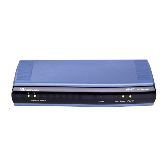
SIP User's Manual 1. Overview 1.2.2 MP-124 Hardware Features The MP-124 hardware features include the following: MP-124 19-inch, 1U rugged enclosure provides up to 24 analog FXS ports, using a single 50-pin Telco connector. LEDs on the front panel that provide information on the device's operating status and the network interface. - Page 18 MediaPack Series Reader’s Notes SIP User's Manual Document #: LTRT-65411...
-
Page 19: Configuration Concepts
To initialize the device by assigning it an IP address, a firmware file (cmp), Note: and a configuration file (ini file), you can use AudioCodes' BootP/TFTP utility, which accesses the device using its MAC address (refer to the Product Reference Manual). - Page 20 MediaPack Series Reader’s Notes SIP User's Manual Document #: LTRT-65411...
-
Page 21: Web-Based Management
SIP User's Manual 3. Web-Based Management Web-Based Management The device's Embedded Web Server (Web interface) provides FCAPS (fault management, configuration, accounting, performance, and security) functionality. The Web interface allows you to remotely configure your device for quick-and-easy deployment, including uploading of configuration (software upgrade) and auxiliary files, and resetting the device. The Web interface provides real-time, online monitoring of the device, including display of alarms and their severity. -
Page 22: Figure 3-1: Enter Network Password Screen
MediaPack Series To access the Web interface, take these 4 steps: Open a standard Web browser application. In the Web browser's Uniform Resource Locator (URL) field, specify the device's IP address (e.g., http://10.1.10.10); the Web interface's 'Enter Network Password' dialog box appears, as shown in the figure below: Figure 3-1: Enter Network Password Screen In the 'User Name' and 'Password' fields, enter the case-sensitive, user name and... -
Page 23: Getting Acquainted With The Web Interface
SIP User's Manual 3. Web-Based Management Getting Acquainted with the Web Interface The figure below displays the general layout of the Graphical User Interface (GUI) of the Web interface: Figure 3-2: Main Areas of the Web Interface GUI The Web GUI is composed of the following main areas: Title bar: Displays the corporate logo and product name. -
Page 24: Toolbar
MediaPack Series 3.3.1 Toolbar The toolbar provides command buttons for quick-and-easy access to frequently required commands, as described in the table below: Table 3-1: Description of Toolbar Buttons Icon Button Description Name Applies parameter settings to the device (refer to ''Saving Submit Configuration'' on page 209). -
Page 25: Navigation Tree
SIP User's Manual 3. Web-Based Management 3.3.2 Navigation Tree The Navigation tree, located in the Navigation pane, displays the menus (pertaining to the menu tab selected on the Navigation bar) used for accessing the configuration pages. The Navigation tree displays a tree-like structure of menus. You can easily drill-down to the required page item level to open its corresponding page in the Work pane. -
Page 26: Displaying Navigation Tree In Basic And Full View
MediaPack Series To navigate to a page, take these 2 steps: Navigate to the required page item, by performing the following: • Drilling-down using the plus signs to expand the menus and submenus • Drilling-up using the minus signs to collapse the menus and submenus Select the required page item;... -
Page 27: Showing / Hiding The Navigation Pane
SIP User's Manual 3. Web-Based Management 3.3.2.2 Showing / Hiding the Navigation Pane The Navigation pane can be hidden to provide more space for elements displayed in the Work pane. This is especially useful when the Work pane displays a page with a table that's wider than the Work pane and to view the all the columns, you need to use scroll bars. -
Page 28: Accessing Pages
MediaPack Series 3.3.3.1 Accessing Pages The configuration pages are accessed by clicking the required page item in the Navigation tree. To open a configuration page in the Work pane, take these 2 steps: On the Navigation bar, click the required tab: •... -
Page 29: Figure 3-7: Toggling Between Basic And Advanced Page View
SIP User's Manual 3. Web-Based Management 3.3.3.2.1 Displaying Basic and Advanced Parameters Some pages provide you with an Advanced Parameter List / Basic Parameter List toggle button that allows you to show or hide advanced parameters (in addition to displaying the basic parameters). -
Page 30: Figure 3-8: Expanding And Collapsing Parameter Groups
MediaPack Series 3.3.3.2.2 Showing / Hiding Parameter Groups Some pages provide groups of parameters, which can be hidden or shown. To toggle between hiding and showing a group, simply click the group name button that appears above each group. The button appears with a down-pointing or up-pointing arrow, indicating that it can be collapsed or expanded when clicked, respectively. -
Page 31: Modifying And Saving Parameters
SIP User's Manual 3. Web-Based Management 3.3.3.3 Modifying and Saving Parameters When you change parameter values on a page, the Edit symbol appears to the right of these parameters. This is especially useful for indicating the parameters that you have currently modified (before applying the changes). -
Page 32: Entering Phone Numbers In Various Tables
MediaPack Series If you enter an invalid parameter value (e.g., not in the range of permitted values) and then click Submit, a message box appears notifying you of the invalid value. In addition, the parameter value reverts to its previous value and is highlighted in red, as shown in the figure below: Figure 3-10: Value Reverts to Previous Valid Value 3.3.3.4... -
Page 33: Figure 3-11: Adding An Index Entry To A Table
SIP User's Manual 3. Web-Based Management To add an entry to a table, take these 2 steps: In the 'Add' field, enter the desired index entry number, and then click Add; an index entry row appears in the table: Figure 3-11: Adding an Index Entry to a Table Click Apply to save the index entry. -
Page 34: Searching For Configuration Parameters
MediaPack Series To organize the index entries in ascending, consecutive order, take the following step: Click Compact; the index entries are organized in ascending, consecutive order, starting from index 0. For example, if you added three index entries 0, 4, and 6, then the index entry 4 is re-assigned index number 1 and the index entry 6 is re-assigned index number 2. -
Page 35: Working With Scenarios
SIP User's Manual 3. Web-Based Management In the 'Search' field, enter the parameter name or sub-string of the parameter name that you want to search. If you have performed a previous search for such a parameter, instead of entering the required string, you can use the 'Search History' drop-down list to select the string (saved from a previous search). -
Page 36: Creating A Scenario
MediaPack Series 3.3.5.1 Creating a Scenario The Web interface allows you to create one Scenario with up to 20 configuration pages, as described in the procedure below: To create a Scenario, take these 10 steps: On the Navigation bar, click the Scenarios tab; a message box appears, requesting you to confirm creation of a Scenario: Figure 3-14: Scenario Creation Confirm Message Box Note: If a Scenario already exists, the Scenario Loading message box appears. -
Page 37: Figure 3-15: Creating A Scenario
SIP User's Manual 3. Web-Based Management Click the Next button located at the bottom of the page; the Step is added to the Scenario and appears in the Scenario Step list: Figure 3-15: Creating a Scenario Repeat steps 5 through 8 to add additional Steps (i.e., pages). When you have added all the required Steps for your Scenario, click the Save &... -
Page 38: Accessing A Scenario
MediaPack Series 3.3.5.2 Accessing a Scenario Once you have created the Scenario, you can access it at anytime by following the procedure below: To access the Scenario, take these 2 steps: On the Navigation bar, select the Scenario tab; a message box appears, requesting you to confirm the loading of the Scenario. -
Page 39: Editing A Scenario
SIP User's Manual 3. Web-Based Management In an opened Scenario Step (i.e., page appears in the Work pane), use the following navigation buttons: • Next: opens the next Step listed in the Scenario. • Previous: opens the previous Step listed in the Scenario. If you reset the device while in Scenario mode, after the device resets, you Note: are returned once again to the Scenario mode. -
Page 40: Saving A Scenario To A Pc
MediaPack Series • Edit the Step Name: In the Navigation tree, select the required Step. In the 'Step Name' field, modify the Step name. In the page, click Next. • Edit the Scenario Name: In the 'Scenario Name' field, edit the Scenario name. In the displayed page, click Next. -
Page 41: Loading A Scenario To The Device
SIP User's Manual 3. Web-Based Management Click the Get Scenario File button; the 'File Download' window appears. Click Save, and then in the 'Save As' window navigate to the folder to where you want to save the Scenario file. When the file is successfully downloaded to your PC, the 'Download Complete' window appears. -
Page 42: Deleting A Scenario
MediaPack Series 3.3.5.6 Deleting a Scenario You can delete the Scenario by using the Delete Scenario File button, as described in the procedure below: To delete the Scenario, take these 4 steps: On the Navigation bar, click the Scenarios tab; a message box appears, requesting you to confirm: Figure 3-19: Scenario Loading Message Box Click OK;... -
Page 43: Exiting Scenario Mode
The figure below shows an example of a customized Title bar. The top image displays the Title bar with AudioCodes logo and product name. The bottom image displays a customized Title bar with a different image logo and product name. -
Page 44: Figure 3-23: Image Download Screen
MediaPack Series 3.3.6.1.1 Replacing the Corporate Logo with an Image You can replace the logo that appears in the Web interface's Title bar, using either the Web interface or the ini file. To replace the default logo with a different image via the Web interface, take these 7 steps: Access the device's Web interface (refer to ''Accessing the Web Interface'' on page 21). -
Page 45: Table 3-2: Ini File Parameters For Changing Logo Image
The corporate logo can be replaced with a text string instead of an image. To replace AudioCodes’ default logo with a text string using the ini file, configure the ini file parameters listed in the table below. (For a description on using the ini file, refer to ''Modifying an ini File'' on page 235.) -
Page 46: Customizing The Product Name
MediaPack Series 3.3.6.2 Customizing the Product Name You can customize the product name (text) that appears in the Title bar, using the ini file parameters listed in the table below. (For a description on using the ini file, refer to ''Modifying an ini File'' on page 235.) Table 3-4: ini File Parameters for Customizing Product Name Parameter... -
Page 47: Getting Help
SIP User's Manual 3. Web-Based Management 3.3.7 Getting Help The Web interface provides you with context-sensitive Online Help. The Online Help provides you with brief descriptions of most of the parameters you'll need to successfully configure the device. The Online Help provides descriptions of parameters pertaining to the currently opened page. -
Page 48: Using The Home Page
MediaPack Series 3.3.8 Using the Home Page The 'Home' page provides you with a graphical display of the device's front panel, displaying color-coded status icons for monitoring the functioning of the device. By default, the 'Home' page is displayed when you access the device's Web interface. When you are configuring the device (in a configuration page), you can always return to the 'Home' page, by simply clicking the Home icon on the toolbar. -
Page 49: Assigning A Name To A Port
SIP User's Manual 3. Web-Based Management Item# / Label Description Displays the status of the ports (channels): Channel / Ports (red): line not connected (only applicable to FXO devices) (grey): channel inactive (blue): handset is off-hook (green): active RTP stream You can also view the channel's port settings (refer to “Viewing Port Information”... -
Page 50: Viewing Analog Port Information
MediaPack Series 3.3.8.2 Viewing Analog Port Information The 'Home' page allows you to view detailed information on a specific FXS or FXO analog port such as RTP/RTCP and voice settings. To view detailed port information, take these 3 steps: Click the port for which you want to view port settings; the shortcut menu appears. Figure 3-30: Shortcut Menu when Clicking Port –... -
Page 51: Logging Off The Web Interface
SIP User's Manual 3. Web-Based Management Figure 3-32: Shortcut Menu when Clicking Port – Reset Channel (e.g. MP-11x) 3.3.9 Logging Off the Web Interface You can log off the Web interface and re-access it with a different user account. For detailed information on the Web User Accounts, refer to User Accounts. -
Page 52: Configuration Tab
MediaPack Series Configuration Tab The Configuration tab on the Navigation bar displays all menus related to device configuration. These menus appear in the Navigation tree and include the following: Network Settings (refer to ''Network Settings'' on page 52) Media Settings (refer to ''Media Settings'' on page 67) Sigtran Configuration (refer to “Sigtran”... -
Page 53: Figure 3-35: Ip Settings Page
SIP User's Manual 3. Web-Based Management To configure the IP settings parameters, take these 4 steps: Open the 'IP Settings' page (Configuration tab > Network Settings menu > IP Settings page item). Figure 3-35: IP Settings Page Configure the IP parameters according to the table below. Click the Submit button to save your changes. - Page 54 MediaPack Series Parameter Description Single IP Settings IP Address IP address of the device. Enter the IP address in dotted-decimal notation, for example, 10.8.201.1. Notes: A warning message is displayed (after clicking Submit) if the entered value is incorrect. After changing the IP address, you must reset the device. Subnet Mask Subnet mask of the device.
-
Page 55: Configuring The Multiple Interface Table
SIP User's Manual 3. Web-Based Management Parameter Description Multiple Interface Settings Multiple Interface Table Click the right-pointing arrow button to open the 'Multiple Interface Table' page. For a description of configuring multiple IP interfaces, refer to ''Configuring the Multiple Interface Table'' on page 55. VLAN (For detailed information on the device's VLAN implementation, refer to ''VLANS and Multiple IPs'' on page 370.) VLAN Mode... -
Page 56: Figure 3-36: Confirmation Message For Accessing The Multiple Interface Table
MediaPack Series To configure the multiple IP interface table, take these 7 steps: Open the 'IP Settings' page (refer to ''Configuring the IP Settings'' on page 52). Under the Multiple Interface Settings group, click the right-arrow button alongside Multiple Interface Table; a confirmation message box appears: Figure 3-36: Confirmation Message for Accessing the Multiple Interface Table Click OK to confirm;... -
Page 57: Table 3-8: Multiple Interface Table Parameters Description
SIP User's Manual 3. Web-Based Management Table 3-8: Multiple Interface Table Parameters Description Parameter Description Table parameters Index of each interface. The range is 0-3. Index Note: Each interface index must be unique. Types of applications that are allowed on the specific interface. [0] OAM = Only Operations, Administration, Maintenance and Provisioning (OAMP) applications (e.g., Web, Telnet, SSH, and SNMP) are allowed on the interface. -
Page 58: Configuring The Application Settings
MediaPack Series Parameter Description interface address. For configuring additional routing rules for other interfaces, refer to ''Configuring the IP Routing Table'' on page 63. Defines the VLAN ID for each interface. When using VLANs, the VLAN ID must be unique for each interface. Incoming traffic tagged with this VLAN ID VLAN ID is routed to the corresponding interface, and outgoing traffic from that interface is tagged with this VLAN ID. -
Page 59: Figure 3-38: Application Settings Page
SIP User's Manual 3. Web-Based Management Figure 3-38: Application Settings Page Configure the Applications parameters according to the table below. Click the Submit button to save your changes. To save the changes to flash memory, refer to ''Saving Configuration'' on page 209. Table 3-9: Application Settings Parameters Parameter Description... - Page 60 [NTPUpdateInterval] The default interval is 86400 (i.e., 24 hours). The range is 0 to 214783647. Note: AudioCodes does not recommend setting this parameter to beyond one month (i.e., 2592000 seconds). Telnet Settings Embedded Telnet Server Enables or disables the device's embedded Telnet server. Telnet is disabled by default for security reasons.
- Page 61 SIP User's Manual 3. Web-Based Management Parameter Description Notes: For defining the STUN server domain name, use the ini file parameter STUNServerDomainName (refer to ''Networking Parameters'' on page 236). This parameter cannot be changed on-the-fly and requires a device reset. STUN Server Primary IP Defines the IP address of the primary STUN server.
-
Page 62: Configuring The Nfs Settings
MediaPack Series 3.4.1.4 Configuring the NFS Settings Network File System (NFS) enables the device to access a remote server's shared files and directories, and to handle them as if they're located locally. You can configure up to five different NFS file systems. As a file system, the NFS is independent of machine types, OSs, and network architectures. -
Page 63: Configuring The Ip Routing Table
SIP User's Manual 3. Web-Based Management Table 3-10: Network Settings -- NFS Settings Parameters Parameter Description The row index of the remote file system. Index The valid range is 0 to 4. The domain name or IP address of the NFS server. If a domain name is Host Or IP provided, a DNS server must be configured. -
Page 64: Figure 3-40: Ip Routing Table Page
MediaPack Series To configure static IP routing, take these 3 steps: Open the 'IP Routing Table' page (Configuration tab > Network Settings menu > IP Routing Table page item). Figure 3-40: IP Routing Table Page In the 'Add a new table entry' group, add a new static routing rule according to the parameters described in the table below. -
Page 65: Configuring The Qos Settings
SIP User's Manual 3. Web-Based Management Parameter Description Multiple Interface Table'' on page 55). Metric The maximum number of allowed routers (hops) between the device and destination. [RoutingTableHopsCountColumn] Note: This parameter must be set to 1 for the routing rule to be valid. Routing entries with Hop Count equals 0 are local routes set automatically by the device. -
Page 66: Table 3-12: Qos Settings Parameters
MediaPack Series Table 3-12: QoS Settings Parameters Parameter Description Priority Settings Network Priority Defines the priority for Network Class of Service (CoS) content. [VLANNetworkServiceClassPriority] The valid range is 0 to 7. The default value is 7. Media Premium Priority Defines the priority for the Premium CoS content and media traffic. -
Page 67: Media Settings
SIP User's Manual 3. Web-Based Management 3.4.2 Media Settings The Media Settings menu allows you to configure the device's channel parameters. These parameters are applied to all the device's channels. This menu contains the following page items: Voice Settings (refer to ''Configuring the Voice Settings'' on page 67) Fax/Modem/CID Settings (refer to ''Configuring the Fax / Modem / CID Settings'' on page 69) RTP/RTCP Settings (refer to ''Configuring the RTP / RTCP Settings'' on page 73) -
Page 68: Table 3-13: Media Settings, Voice Settings Parameters
MediaPack Series Configure the Voice parameters according to the table below. Click the Submit button to save your changes. To save the changes to flash memory, refer to ''Saving Configuration'' on page 209. Table 3-13: Media Settings, Voice Settings Parameters Parameter Description Voice Volume... - Page 69 SIP User's Manual 3. Web-Based Management Parameter Description DTMF Volume (-31 to 0 dB) DTMF gain control value (in decibels) to the or analog side. The valid range is -31 to 0 dB. The default value is -11 dB. [DTMFVolume] Enable Answer Detector N/A.
-
Page 70: Configuring The Fax / Modem / Cid Settings
MediaPack Series 3.4.2.2 Configuring the Fax / Modem / CID Settings The 'Fax/Modem/CID Settings' page is used for configuring fax, modem, and Caller ID (CID) parameters. To configure the fax, modem, and CID parameters, take these 4 steps: Open the 'Fax/Modem/CID Settings' page (Configuration tab > Media Settings menu >... - Page 71 SIP User's Manual 3. Web-Based Management Parameter Description Caller ID Transport Type Determines the device's behavior for Caller ID detection. [CallerIDTransportType] [0] Disable = Caller ID is not detected - DTMF digits remain in the voice stream. [1] Relay = Caller ID is detected - DTMF digits are erased from the voice stream.
- Page 72 MediaPack Series Parameter Description V.23 Modem Transport V.23 Modem Transport Type used by the device. Type [0] Disable = Disable (Transparent) [V23ModemTransportTy [1] Enable Relay = N/A [2] Enable Bypass = (default) [3] Events Only = Transparent with Events V.32 Modem Transport V.32 Modem Transport Type used by the device.
- Page 73 SIP User's Manual 3. Web-Based Management Parameter Description Fax/Modem Bypass Coder Coder used by the device when performing fax/modem bypass. Usually, Type high-bit-rate coders such as G.711 should be used. [FaxModemBypassCode [0] G.711Alaw= G.711 A-law 64 (default). rType] [1] G.711Mulaw = G.711 μ-law. Fax/Modem Bypass Number of (20 msec) coder payloads that are used to generate a Packing Factor...
-
Page 74: Configuring The Rtp / Rtcp Settings
MediaPack Series 3.4.2.3 Configuring the RTP / RTCP Settings The 'RTP/RTCP Settings' page allows you to configure the Real-Time Transport Protocol (RTP) and Real-Time Transport (RTP) Control Protocol (RTCP) parameters. To configure the RTP / RTCP parameters, take these 4 steps: Open the 'RTP/RTCP Settings' page (Configuration tab >... - Page 75 SIP User's Manual 3. Web-Based Management Parameter Description Packing Factor N/A. Controlled internally by the device according to the selected coder. [RTPPackingFactor] Basic RTP Packet Interval N/A. Controlled internally by the device according to the selected coder. [BasicRTPPacketInterval] RTP Directional Control N/A.
-
Page 76: Configuring The General Media Settings
MediaPack Series Parameter Description message is generated: 'invalid local RTP port'. For detailed information on the default RTP/RTCP/T.38 port allocation, refer to the Product Reference Manual. Remote RTP Base UDP Port Determines the lower boundary of UDP ports used for RTP, RTCP and T.38 by a remote device. -
Page 77: Configuring The Hook-Flash Settings
SIP User's Manual 3. Web-Based Management Figure 3-45: General Media Settings Page Configure the general media parameters according to the table below. Click the Submit button to save your changes. To save the changes to flash memory, refer to ''Saving Configuration'' on page 209. Table 3-16: Media Settings Parameters Parameter Description... -
Page 78: Configuring Media Security
MediaPack Series Parameter Description Max. Flash-Hook Defines the hook-flash period (in msec) for both analog and IP sides. Detection Period [msec] For the IP side, it defines the hook-flash period that is reported to the IP. [FlashHookPeriod] For the analog side, it defines the following: FXS interfaces: Maximum hook-flash detection period. -
Page 79: Security Settings
SIP User's Manual 3. Web-Based Management Parameter Description MP-118: 6 available channels MP-114: 3 available channels MP-112: No reduction Media Security Behavior Determines the device's mode of operation when SRTP is used (EnableMediaSecurity = 1). [MediaSecurityBehaviour] [0] Preferable = The device initiates encrypted calls. If negotiation of the cipher suite fails, an unencrypted call is established. -
Page 80: Configuring The Web User Accounts
MediaPack Series 3.4.3.1 Configuring the Web User Accounts To prevent unauthorized access to the Web interface, two Web user accounts are available (primary and secondary) with assigned user name, password, and access level. When you login to the Web interface, you are requested to provide the user name and password of one of these Web user accounts. -
Page 81: Figure 3-48: Web User Accounts Page (For Users With 'Security Administrator' Privileges)
SIP User's Manual 3. Web-Based Management To change the Web user accounts attributes, take these 4 steps: Open the 'Web User Accounts' page (Configuration tab > Security Settings menu > Web User Accounts page item). Figure 3-48: Web User Accounts Page (for Users with 'Security Administrator' Privileges) Note: If you are logged into the Web interface as the Security Administrator, both Web user accounts are displayed on the 'Web User Accounts' page (as shown above). -
Page 82: Configuring The Web And Telnet Access List
MediaPack Series To change the password of an account, perform the following: In the field 'Current Password', enter the current password. In the fields 'New Password' and 'Confirm New Password', enter the new password (maximum of 19 case-sensitive characters). Click Change Password; if you are currently logged into the Web interface with this account, the 'Enter Network Password' dialog box appears, requesting you to enter the new password. -
Page 83: Figure 3-49: Web & Telnet Access List Page - Add New Entry
SIP User's Manual 3. Web-Based Management To add authorized IP addresses for Web and Telnet interfaces access, take these 4 steps: Open the 'Web & Telnet Access List' page (Configuration tab > Security Settings menu > Web & Telnet Access List page item). Figure 3-49: Web &... -
Page 84: Configuring The Firewall Settings
MediaPack Series 3.4.3.3 Configuring the Firewall Settings The device provides an internal firewall, allowing you (the security administrator) to define network traffic filtering rules. You can add up to 50 ordered firewall rules. For each packet received on the network interface, the table is scanned from the top down until a matching rule is found. -
Page 85: Table 3-21: Internal Firewall Parameters
SIP User's Manual 3. Web-Based Management To activate a de-activated rule, take these 2 steps: In the 'Edit Rule' column, select the de-activated rule that you want to activate. Click the Activate button; the rule is activated. To de-activate an activated rule, take these 2 steps: In the 'Edit Rule' column, select the activated rule that you want to de-activate.. -
Page 86: Configuring The Certificates
MediaPack Series Parameter Description Action Upon Match Action upon match (i.e., 'Allow' or 'Block'). [AccessList_Allow_Type] Match Count A read-only field providing the number of packets accepted / rejected by the specific rule. [AccessList_MatchCount] 3.4.3.4 Configuring the Certificates The 'Certificates' page is used for the following: Replacing the server certificate (refer to ''Server Certificate Replacement'' on page 86) Replacing the client certificates (refer to ''Client Certificates'' on page 88) Regenerating Self-Signed Certificates (refer to ''Self-Signed Certificates'' on page 89) - Page 87 SIP User's Manual 3. Web-Based Management In the 'Subject Name' field, enter the DNS name, and then click Generate CSR. A textual certificate signing request that contains the SSL device identifier is displayed. Copy this text and send it to your security provider. The security provider (also known as Certification Authority or CA) signs this request and then sends you a server certificate for the device.
-
Page 88: Figure 3-53: Ike Table Listing Loaded Certificate Files
MediaPack Series To apply the loaded certificate for IPsec negotiations, take these 2 steps: Open the ‘IKE Table’ page (refer to ''Configuring the IKE Table'' on page 97); the 'Loaded Certificates Files' group lists the newly uploaded certificates, as shown below: Figure 3-53: IKE Table Listing Loaded Certificate Files Click the Apply button to load the certificates;... - Page 89 SIP User's Manual 3. Web-Based Management When operation complete, file parameter HTTPSRequireClientCertificates to 1. Save the configuration (refer to ''Saving Configuration'' on page 209), and then restart the device. When a user connects to the secured Web server: If the user has a client certificate from a CA that is listed in the Trusted Root Certificate file, the connection is accepted and the user is prompted for the system password.
-
Page 90: Configuring The General Security Settings
MediaPack Series 3.4.3.5 Configuring the General Security Settings The 'General Security Settings' page is used to configure various security features. To configure the general security parameters, take these 4 steps: Open the 'General Security Settings' page (Configuration tab > Security Settings menu >... -
Page 91: Table 3-22: General Security Parameters
SIP User's Manual 3. Web-Based Management Table 3-22: General Security Parameters Parameter Description HTTP Authentication Mode Determines the authentication mode for the Web interface. [WebAuthMode] [0] Basic Mode = Basic authentication (clear text) is used (default). [1] Digest When Possible = Digest authentication (MD5) is used. - Page 92 MediaPack Series Parameter Description RADIUS Authentication Server IP Address IP address of the RADIUS authentication server. [RADIUSAuthServerIP] RADIUS Authentication Server Port Port number of the RADIUS authentication server. The default value is 1645. [RADIUSAuthPort] RADIUS Shared Secret 'Secret' used to authenticate the device to the RADIUS server. Should be a cryptographically strong password.
- Page 93 SIP User's Manual 3. Web-Based Management Parameter Description [0] Disable = IPSec is disabled (default). [1] Enable = IPSec is enabled. Dead Peer Detection Mode Enables the Dead Peer Detection (DPD) 'keep-alive' mechanism (according to RFC 3706) to detect loss of peer [IPSecDPDMode] connectivity.
-
Page 94: Configuring The Ipsec Table
MediaPack Series Parameter Description server or client for the TLS connection. When a remote certificate is received and this parameter is not disabled, the SubjectAltName value is compared with the list of available Proxies. If a match is found for any of the configured Proxies, the TLS connection is established. -
Page 95: Figure 3-55: Ipsec Table Page
SIP User's Manual 3. Web-Based Management To configure the IPSec SPD table, take these 5 steps: Open the ‘IPSec Table’ page (Configuration tab > Security Settings menu > IPSec Table page item). Figure 3-55: IPSec Table Page From the ‘Policy Index’ drop-down list, select the rule you want to edit (up to 20 policy rules can be configured). -
Page 96: Table 3-24: Ipsec Spd Table Configuration Parameters
MediaPack Series Table 3-24: IPSec SPD Table Configuration Parameters Parameter Name Description IPSec Mode Defines the IPSec mode of operation. [IPSecMode] [0] Transport (Default) [1] Tunneling Remote Tunnel IP Address Defines the IP address of the remote IPSec tunneling device. [IPSecPolicyRemoteTunnelIPAddress] Note: This parameter is available only if the parameter IPSecMode is set to... -
Page 97: Configuring The Ike Table
SIP User's Manual 3. Web-Based Management Parameter Name Description IKE Second Phase Parameters (Quick Mode) SA Lifetime (sec) Determines the time (in seconds) that the SA negotiated in the second IKE session (quick mode) is valid. After [PsecPolicyLifeInSec] the time expires, the SA is re-negotiated. The default value is 28,800 (i.e., 8 hours). -
Page 98: Figure 3-56: Ike Table Page
MediaPack Series To configure the IKE table, take these 5 steps: Open the ‘IKE Table’ page (Configuration tab > Security Settings menu > IKE Table page item). Figure 3-56: IKE Table Page From the ‘Policy Index’ drop-down list, select the peer you want to edit (up to 20 peers can be configured). -
Page 99: Table 3-26: Ike Table Configuration Parameters
SIP User's Manual 3. Web-Based Management The parameters described in the following table are used to configure the first phase (main mode) of the IKE negotiation for a specific peer. A different set of parameters can be configured for each of the 20 available peers. Table 3-26: IKE Table Configuration Parameters Parameter Name Description... -
Page 100: Protocol Configuration
MediaPack Series Parameter Name Description [2] Triple DES-CBC [3] AES-CBC Not Defined (default) First to Fourth Proposal Determines the authentication protocol used in the main mode Authentication Type negotiation for up to four proposals. For the ini file parameter, X depicts the proposal number (0 to 3). -
Page 101: Figure 3-57: Sip General Parameters
SIP User's Manual 3. Web-Based Management 3.4.4.1.1 SIP General Parameters The 'SIP General Parameters' page is used to configure general SIP parameters. To configure the general SIP protocol parameters, take these 4 steps: Open the 'SIP General Parameters' page (Configuration tab > Protocol Configuration menu >... -
Page 102: Table 3-27: Sip General Parameters (Protocol Definition)
MediaPack Series Configure the parameters according to the table below. Click the Submit button to save your changes. To save the changes to flash memory, refer to ''Saving Configuration'' on page 209. Table 3-27: SIP General Parameters (Protocol Definition) Parameter Description PRACK Mode PRACK (Provisional Acknowledgment) mechanism mode for 1xx SIP... - Page 103 SIP User's Manual 3. Web-Based Management Parameter Description Note that to send a 183 response, you must also set the parameter ProgressIndicator2IP to 1. If it is equal to 0, 180 Ringing response is sent. 183 Message Behavior Defines the response of the device upon receipt of a SIP 183 response. [SIP183Behaviour] [0] Progress = A 183 response (without SDP) does not cause the device to play a ringback tone (default).
- Page 104 MediaPack Series Parameter Description Fax Signaling Method Determines the SIP signaling method for establishing and transmitting a fax session after a fax is detected. [IsFaxUsed] [0] No Fax = No fax negotiation using SIP signaling. Fax transport method is according to the parameter FaxTransportMode (default). [1] T.38 Relay = Initiates T.38 fax relay.
- Page 105 SIP User's Manual 3. Web-Based Management Parameter Description SIP Transport Type Determines the default transport layer for outgoing SIP calls initiated by the device. [SIPTransportType] [0] UDP (default) [1] TCP [2] TLS (SIPS) Notes: It's recommended to use TLS for communication with a SIP Proxy and not for direct device-to-device communication.
- Page 106 MediaPack Series Parameter Description Use user=phone in From Determines whether to add 'user=phone' string in the From header. Header [0] No = Doesn't use 'user=phone' string in From header (default). [IsUserPhoneInFrom] [1] Yes = 'user=phone' string is part of the From header. Use Tel URI for Asserted Determines the format of the URI in the P-Asserted-Identity and P- Identity...
- Page 107 SIP User's Manual 3. Web-Based Management Parameter Description Enable History-Info Enables usage of the History-Info header. Header [0] Disable = Disable (default) [EnableHistoryInfo] [1] Enable = Enable User Agent Client (UAC) Behavior: Initial request: The History-Info header is equal to the Request URI. If a PSTN Redirect number is received, it is added as an additional History-Info header with an appropriate reason.
- Page 108 MediaPack Series Parameter Description Use Display Name as Determines the use of Source Number and Display Name for IP-to-Tel Source Number calls. [UseDisplayNameAsSou [0] No = If IP Display Name is received, the IP Source Number is rceNumber] used as the Tel Source Number and the IP Display Name is used as the Tel Display Name.
- Page 109 Defines the string that is used in the SIP request header User-Agent and SIP response header Server. If not configured, the default string [UserAgentDisplayInfo] 'AudioCodes product-name s/w-version' is used (e.g., User-Agent: Audiocodes-Sip-Gateway-MediaPack/v.5.40.010.006). When configured, the string 'UserAgentDisplayInfo s/w-version' is used (e.g., User-Agent: MyNewOEM/v.5.40.010.006).
- Page 110 MediaPack Series Parameter Description SDP Session Owner Determines the value of the Owner line ('o' field) in outgoing SDP messages. [SIPSDPSessionOwner] The valid range is a string of up to 39 characters. The default value is 'AudiocodesGW'. For example: o=AudiocodesGW 1145023829 1145023705 IN IP4 10.33.4.126 Subject Defines the value of the Subject header in outgoing INVITE messages.
- Page 111 SIP User's Manual 3. Web-Based Management Parameter Description [1] Enable. Note: P-Associated-URIs in registration responses is handled only if the device is registered per endpoint. Source Number Determines the SIP header used to determine the Source Number in Preference incoming INVITE messages. [SourceNumberPreferen “”...
-
Page 112: Figure 3-58: Proxy & Registration
MediaPack Series 3.4.4.1.2 Proxy & Registration Parameters The 'Proxy & Registration' page allows you to configure parameters that are associated with Proxy and Registration. To view whether the device or its endpoints have registered to a SIP Note: Registrar/Proxy server, refer to ''Registration Status'' on page 226. To configure the Proxy &... -
Page 113: Table 3-28: Proxy & Registration Parameters
SIP User's Manual 3. Web-Based Management Table 3-28: Proxy & Registration Parameters Parameter Description Proxy Parameters Use Default Proxy Enables the use of a SIP Proxy server. [IsProxyUsed] [0] No = Proxy isn't used - the internal routing table is used instead (default). - Page 114 MediaPack Series Parameter Description Prefer Routing Table Determines if the device's internal routing table takes precedence over a Proxy for routing calls. [PreferRouteTable] [0] No = Only a Proxy server is used to route calls (default). [1] Yes = The device checks the routing rules in the 'Tel to IP Routing' table for a match with the Tel-to-IP call.
- Page 115 SIP User's Manual 3. Web-Based Management Parameter Description re-routes the call according to the Standard mode [0]. If DNS resolution fails, the device attempts to route the call to the Proxy. If routing to the Proxy also fails, the Redirect / Transfer request is rejected.
- Page 116 MediaPack Series Parameter Description Registration Time Defines the time interval (in seconds) for registering to a Proxy server. The value is used in the Expires header. In addition, this parameter [RegistrationTime] defines the time interval between Keep-Alive messages when the parameter EnableProxyKeepAlive is set to 2 (REGISTER).
- Page 117 SIP User's Manual 3. Web-Based Management Parameter Description Gateway Registration Name Defines the user name that is used in the From and To headers in REGISTER messages. If no value is specified (default) for this [GWRegistrationName] parameter, the UserName parameter is used instead. Note: This parameter is applicable only for single registration per device (i.e., AuthenticationMode is set to 1).
- Page 118 MediaPack Series Parameter Description an SRV query is sent according to the information received in the NAPTR response. If the NAPTR query fails, an SRV query is performed according to the configured transport type. If the Proxy IP address parameter contains a domain name with port definition (e.g., ProxyIP = domain.com:5080), the device performs a regular DNS A-record query.
- Page 119 SIP User's Manual 3. Web-Based Management Parameter Description Cnonce Cnonce string used by the SIP server and client to provide mutual authentication. (Free format, i.e., 'Cnonce = 0a4f113b'). The default is [Cnonce] 'Default_Cnonce'. Authentication Mode Determines the device's registration and authentication method. [AuthenticationMode] [0] Per Endpoint = Registration and Authentication separately for each endpoint.
-
Page 120: Figure 3-59: Proxy Sets Table
MediaPack Series Parameter Description Mutual Authentication Mode Determines the device's mode of operation when Authentication and Key Agreement (AKA) Digest Authentication is used. [MutualAuthenticationMod [0] Optional = Incoming requests that don't include AKA authentication information are accepted (default). [1] Mandatory = Incoming requests that don't include AKA authentication information are rejected. -
Page 121: Table 3-29: Proxy Sets Table Parameters
SIP User's Manual 3. Web-Based Management From the Proxy Set ID drop-down list, select an ID for the desired group. Configure the Proxy parameters according to the following table. Click the Submit button to save your changes. To save the changes to flash memory, refer to ''Saving Configuration'' on page 209. Table 3-29: Proxy Sets Table Parameters Parameter Description... - Page 122 MediaPack Series Parameter Description REGISTER). To use Proxy Redundancy, you must specify one or more redundant Proxies. When a port number is specified (e.g., domain.com:5080), DNS NAPTR/SRV queries aren't performed, even if ProxyDNSQueryType is set to 1 or 2. Transport Type The transport type per Proxy server.
- Page 123 SIP User's Manual 3. Web-Based Management Parameter Description defined interval, as configured by the parameter RegistrationTime. Any response from the Proxy, either success (200 OK) or failure (4xx response) is considered as if the Proxy is communicating correctly. Notes: This parameter must be set to 'Using OPTIONS' when Proxy redundancy is used.
-
Page 124: Figure 3-60: Coders
MediaPack Series The coders supported by the device are listed in the table below: Table 3-30: Supported Coders Coder Name Packetization Time Rate Payload Type Silence Suppression Disable [0] G.711 A-law 10, 20 (default), 30, Always 64 Always 8 40, 50, 60, 80, 100, [g711Alaw64k] Enable [1] Disable [0]... - Page 125 SIP User's Manual 3. Web-Based Management From the 'Packetization Time' drop-down list, select the packetization time (in msec) for the selected coder. The packetization time determines how many coder payloads are combined into a single RTP packet. From the 'Rate' drop-down list, select the bit rate (in kbps) for the selected coder. In the 'Payload Type' field, if the payload type for the selected coder is dynamic, enter a value from 0 to 120 (payload types of 'well-known' coders cannot be modified).
-
Page 126: Figure 3-61: Dtmf & Dialing
MediaPack Series Figure 3-61: DTMF & Dialing Page Configure the DTMF and dialing parameters according to the table below. Click the Submit button to save your changes. To save the changes to flash memory, refer to ''Saving Configuration'' on page 209. Table 3-31: DTMF and Dialing Parameters Parameter Description... - Page 127 SIP User's Manual 3. Web-Based Management Parameter Description relay packets. Therefore, it is always correct to include the 'telephony- event' parameter as default in the SDP. However, some devices use the absence of the 'telephony-event' in the SDP to decide to send DTMF digits in-band using G.711 coder.
- Page 128 MediaPack Series Parameter Description Hook-Flash Option Determines the supported hook-flash Transport Type (i.e., method by which hook-flash is sent and received). [HookFlashOption] [0] Not Supported = Hook-Flash indication isn't sent (default). [1] INFO = Send proprietary INFO message with Hook-Flash indication.
-
Page 129: Configuring The Sip Advanced Parameters
SIP User's Manual 3. Web-Based Management Parameter Description Enable Special Digits Determines whether the asterisk (*) and pound (#) digits can be used. [IsSpecialDigits] [0] Disable = Use '*' or '#' to terminate number collection (refer to the parameter UseDigitForSpecialDTMF). (Default.) [1] Enable = Allows '*' and '#' for telephone numbers dialed by a user or for the endpoint telephone number. -
Page 130: Figure 3-62: Advanced Parameters
MediaPack Series 3.4.4.2.1 Advanced Parameters The 'Advanced Parameters' page allows you to configure general control protocol parameters. To configure the advanced general protocol parameters, take these 4 steps: Open the 'Advanced Parameters' page (Configuration tab > Protocol Configuration menu > SIP Advanced Parameters submenu > Advanced Parameters page item). Figure 3-62: Advanced Parameters Page Configure the parameters according to the table below. -
Page 131: Table 3-32: Advanced Parameters Description
SIP User's Manual 3. Web-Based Management Table 3-32: Advanced Parameters Description Parameter Description General IP Security Determines whether the device accepts SIP calls received from only IP addresses defined in the 'Tel to IP Routing' table (refer to ''Tel to IP [SecureCallsFromIP] Routing Table'' on page 160). - Page 132 MediaPack Series Parameter Description times. For example (for FXS/FXO interfaces), the called number can be as follows: d1005, dpp699, p9p300. To add the 'd' and 'p' digits, use the usual number manipulation rules. To use this feature with FXO interfaces, configure the device to operate in one-stage dialing mode.
- Page 133 SIP User's Manual 3. Web-Based Management Parameter Description If the polarity reversal service is enabled, the FXS interface changes the line polarity on call answer and then changes it back on call release. The FXO interface sends a 200 OK response when polarity reversal signal is detected (applicable only to one-stage dialing) and releases a call when a second polarity reversal signal is detected.
- Page 134 MediaPack Series Parameter Description Silence Detection Period Duration of silence period (in seconds) prior to call disconnection. [sec] The range is 10 to 28,800 (i.e., 8 hours). The default is 120 seconds. [FarEndDisconnectSile ncePeriod] Silence Detection Silence detection method. Method [0] None = Silence detection option is disabled.
- Page 135 SIP User's Manual 3. Web-Based Management Parameter Description [1] 1 = Flow debugging is enabled. [2] 2 = Flow and device interface debugging are enabled. [3] 3 = Flow, device interface, and stack interface debugging are enabled. [4] 4 = Flow, device interface, stack interface, and session manager debugging are enabled.
- Page 136 MediaPack Series Parameter Description Default Release Cause Default Release Cause (to IP) for IP-to-Tel calls when the device initiates a call release and an explicit matching cause for this release isn't found. [DefaultReleaseCause] The default release cause is NO_ROUTE_TO_DESTINATION (3). Other common values include NO_CIRCUIT_AVAILABLE (34), DESTINATION_OUT_OF_ORDER (27), etc.
- Page 137 SIP User's Manual 3. Web-Based Management Parameter Description Enable Calls Cut Enables users to receive incoming IP calls while the port is in off-hook Through state. [CutThrough] [0] Disable = Disabled (default). [1] Enable = Enabled. If enabled, the FXS interface answers the call and 'cuts through' the voice channel if there is no other active call on the port, even if the port is in off- hook state.
- Page 138 MediaPack Series Parameter Description Emergency Calls Emergency Numbers Defines a list of numbers which are defined as 'emergency numbers'. When one of these numbers is dialed, the outgoing INVITE message [EmergencyNumbers] includes the Priority and Resource-Priority headers. If the user sets the phone on-hook, the call is not disconnected, but instead a Hold Re- INVITE request is sent to the remote party.
-
Page 139: Figure 3-63: Supplementary Services
SIP User's Manual 3. Web-Based Management Figure 3-63: Supplementary Services Page Configure the supplementary services parameters according to the table below. Click the Submit button to save your changes, or click the Subscribe to MWI or Unsubscribe to MWI buttons to save your changes and to subscribe / unsubscribe to the MWI server. -
Page 140: Table 3-33: Supplementary Services Parameters
MediaPack Series Table 3-33: Supplementary Services Parameters Parameter Description Enable Hold Allows users (connected to the device) to place a call on hold. [EnableHold] [0] Disable = Disables the Hold service. [1] Enable = Enables the Hold service (default). If the Hold service is enabled, a user can place the call on hold (or remove from hold) using the hook-flash. - Page 141 SIP User's Manual 3. Web-Based Management Parameter Description Enable Call Forward Determines whether Call Forward is enabled. [EnableForward] [0] Disable = Disable the Call Forward service. [1] Enable = Enable Call Forward service (using REFER) (default). For FXS interfaces, the 'Call Forward' table (refer to “Call Forward” on page 178) must be defined to use the Call Forward service.
- Page 142 MediaPack Series Parameter Description If the Caller ID service is enabled, then for FXS interfaces, calling number and Display text (from IP) are sent to the device's port. For FXO interfaces, the Caller ID signal is detected and sent to IP in the SIP INVITE message (as 'Display' element).
- Page 143 SIP User's Manual 3. Web-Based Management Parameter Description MWI Analog Lamp Enables visual display of MWI. [MWIAnalogLamp] [0] Disable = Disable (default). [1] Enable = Enables visual Message Waiting Indication by supplying line voltage of approximately 100 VDC to activate the phone's lamp. Note: This parameter is applicable only for FXS interfaces.
- Page 144 MediaPack Series Parameter Description MWI Subscribe Retry Subscription retry time (in seconds) after last subscription failure. Time The default is 120 seconds. The range is 10 to 7200. [SubscribeRetryTime] Conference Parameters Enable 3-Way Conference Enables or disables the 3-Way Conference feature. [Enable3WayConference [0] Disable = Disable (default) [1] Enable = Enables 3-way conferencing...
-
Page 145: Figure 3-64: Metering Tones
SIP User's Manual 3. Web-Based Management To configure the Metering tones, take these 4 steps: Open the 'Metering Tones' page (Configuration tab > Protocol Configuration menu > SIP Advanced Parameters submenu > Metering Tones page item). Figure 3-64: Metering Tones Page Configure the Metering tones parameters according to the table below. -
Page 146: Figure 3-65: Charge Codes Table
MediaPack Series 3.4.4.2.4 Charge Codes Table The 'Charge Codes Table' page is used to configure the metering tones (and their time interval) that the FXS interfaces generate to the Tel side. To associate a charge code to an outgoing Tel-to-IP call, use the 'Tel to IP Routing' table. Notes: •... -
Page 147: Figure 3-66: Keypad Features
SIP User's Manual 3. Web-Based Management 3.4.4.2.5 Keypad Features The 'Keypad Features' page (applicable only to FXS interfaces) enables you to activate and deactivate the following features directly from the connected telephone's keypad: Call Forward (refer to ''Call Forward'' on page 178) Caller ID Restriction (refer to ''Caller ID'' on page 177) Hotline (refer to ''Automatic Dialing'' on page 175) Notes:... -
Page 148: Table 3-35: Keypad Features Parameters Description
MediaPack Series Table 3-35: Keypad Features Parameters Description Parameter Description Forward (Note: The forward type and number can be viewed in the 'Call Forward' table - refer to ''Call Forward'' on page 178.) Unconditional Keypad sequence that activates the immediate call forward option. [KeyCFUnCond] No Answer Keypad sequence that activates the forward on no answer option. - Page 149 SIP User's Manual 3. Web-Based Management Parameter Description of the destination phone number. For both options, after the phone number is collected, it's sent to the transferee in a SIP REFER request (without a Replaces header). The call is then terminated and a confirmation tone is played to the phone. If the phone number collection fails due to a mismatch, a reorder tone is played to the phone.
-
Page 150: Figure 3-67: Sas Configuration
MediaPack Series To configure the Stand-Alone Survivability parameters, take these 4 steps: Open the 'SAS Configuration' page (Configuration tab > Protocol Configuration menu > SIP Advanced Parameters submenu > Stand-Alone Survivability page item). Figure 3-67: SAS Configuration Page Configure the parameters according to the table below. Click the Submit button to apply your changes. -
Page 151: Configuring The Number Manipulation Tables
SIP User's Manual 3. Web-Based Management Parameter Description SAS Registration Time Determines the value of the SIP Expires header that is sent in a 200 OK response to an incoming REGISTER message when in SAS [SASRegistrationTime] 'Emergency Mode'. The valid range is 0 to 2,000,000. The default value is 20. Short Number Length This parameter is obsolete;... -
Page 152: Figure 3-68: Source Phone Number Manipulation Table For Tel-To-Ip Calls
MediaPack Series The number manipulation is configured in the following tables: For Tel-to-IP calls: • Destination Phone Number Manipulation Table for Tel-to-IP Calls (NumberMapTel2IP ini file parameter) • Source Phone Number Manipulation Table for Tel-to-IP Calls (SourceNumberMapTel2IP ini file parameter) For IP-to-Tel calls: •... -
Page 153: Table 3-37: Number Manipulation Parameters Description
SIP User's Manual 3. Web-Based Management • When the source number is 1001876, it is changed to 587623. • When the source number is 1234510012001, it is changed to 20018. • When the source number is 3122, it is changed to 2312. From the 'Table Index' drop-down list, select the range of entries that you want to edit (up to 20 entries can be configured for Source Number IP-to-Tel Manipulation, up to 120 entries can be configured for Source Number Tel-to-IP Manipulation, and up to... - Page 154 MediaPack Series Parameter Description originating from this Source IP Group is sent to the Serving IP Group. In this scenario, this table is used only if the parameter PreferRouteTable is set to 1. Destination Prefix Destination (called) telephone number prefix. An asterisk (*) represents any number.
-
Page 155: Table 3-38: Dialing Plan Notations
SIP User's Manual 3. Web-Based Management 3.4.4.3.1 Dialing Plan Notation The dialing plan notation applies to the Number Manipulation tables, 'Tel to IP Routing' table (refer to ''Tel to IP Routing Table'' on page 160), and 'IP to Hunt Group Routing' table (refer to ''IP to Trunk Group Routing'' on page 163). -
Page 156: Figure 3-69: Phone Context Table
MediaPack Series To configure the Phone-Context tables, take these 4 steps: Open the 'Phone Context Table' page (Configuration tab > Protocol Configuration menu > Manipulation Tables submenu > Phone Context Table page item). Figure 3-69: Phone Context Table Page Configure the Phone Context table according to the table below. Click the Submit button to save your changes. -
Page 157: Configuring The Routing Tables
SIP User's Manual 3. Web-Based Management Parameter Description Level 0 Regional (Local) [4]. If you selected E.164 Public as the NPI, you can select Unknown [0], International [1], National [2], Network Specific [3], Subscriber [4], or Abbreviated [6]. The Phone-Context SIP URI parameter. Phone Context 3.4.4.4 Configuring the Routing Tables... -
Page 158: Table 3-40: Routing General Parameters Description
MediaPack Series Configure the general parameters according to the table below. Click the Submit button to save your changes. To save the changes to flash memory, refer to ''Saving Configuration'' on page 209. Table 3-40: Routing General Parameters Description Parameter Description Add Hunt Group ID as Prefix Determines whether the device's Hunt Group ID is added as a prefix... - Page 159 SIP User's Manual 3. Web-Based Management Parameter Description Enable Alt Routing Tel to IP Enables the Alternative Routing feature for Tel-to-IP calls. [AltRoutingTel2IPEnable] [0] Disable = Disables the Alternative Routing feature (default). [1] Enable = Enables the Alternative Routing feature. [2] Status Only = The Alternative Routing feature is disabled, but read-only information on the Quality of Service of the destination IP addresses is provided.
- Page 160 MediaPack Series Parameter Description Max Allowed Packet Loss for Packet loss percentage at which the IP connection is considered a Alt Routing [%] failure and Alternative Routing mechanism is activated. The range is 1 to 20%. The default value is 20%. [IPConnQoSMaxAllowedPL] Max Allowed Delay for Alt Transmission delay (in msec) at which the IP connection is...
-
Page 161: Figure 3-71: Tel To Ip Routing
SIP User's Manual 3. Web-Based Management Assign Profiles to destination addresses (also when a Proxy is used). Alternative Routing (when a Proxy isn't used): an alternative IP destination for telephone number prefixes is available. To associate an alternative IP address to a called telephone number prefix, assign it with an additional entry (with a different IP address), or use an FQDN that resolves into two IP addresses. -
Page 162: Table 3-41: Tel To Ip Routing Table Parameters Description
MediaPack Series Configure the Tel to IP Routing table according to the table below. Click the Submit button to save your changes. To save the changes to flash memory, refer to ''Saving Configuration'' on page 209. Table 3-41: Tel to IP Routing Table Parameters Description Parameter Description Tel to IP Routing Mode... - Page 163 SIP User's Manual 3. Web-Based Management Parameter Description Port The destination port to where you want to route the Tel-to-IP call. [PREFIX_DestPort] Transport Type The transport layer type for sending the Tel-to-IP calls: [PREFIX_TransportType] [-1] Not Configured [0] UDP [1] TCP [2] TLS Note: When 'Not Configured' is selected, the transport type defined by the parameter SIPTransportType (refer to ''SIP General...
- Page 164 MediaPack Series 3.4.4.4.3 IP to Trunk Group Routing Table The 'IP to Hunt Group Routing Table' page provides a table for routing incoming IP calls to groups of channels (FXS/FXO endpoints)called Hunt Groups. Hunt Group ID's are assigned to the device's channels in the 'Endpoint Phone Number' page (refer to “Configuring the Endpoint Phone Numbers”...
-
Page 165: Figure 3-72: Ip To Hunt Group Routing
SIP User's Manual 3. Web-Based Management Figure 3-72: IP to Hunt Group Routing Page From the 'Routing Index' drop-down list, select the range of entries that you want to add. Configure the table according to the table below. Click the Submit button to save your changes. To save the changes so they are available after a power failure, refer to ''Saving Configuration'' on page 209. - Page 166 MediaPack Series Parameter Description Dest. Phone Prefix Represents a called telephone number prefix. The prefix can be 1 to 49 digits long. [PstnPrefix_DestPrefix] Note: For notations representing multiple numbers, refer to ''Dialing Plan Notation'' on page 155. Source Phone Prefix Represents a calling telephone number prefix.
-
Page 167: Figure 3-73: Internal Dns Table
SIP User's Manual 3. Web-Based Management To configure the internal DNS table, take these 6 steps: Open the 'Internal DNS Table' page (Configuration tab > Protocol Configuration menu > Routing Tables submenu > Internal DNS Table page item). Figure 3-73: Internal DNS Table Page In the 'Domain Name' field, enter the host name to be translated. -
Page 168: Figure 3-74: Internal Srv Table Screen
MediaPack Series To configure the Internal SRV table, take these 9 steps: Open the 'Internal SRV Table' page (Configuration tab > Protocol Configuration menu > Routing Tables submenu > Internal SRV Table page item). Figure 3-74: Internal SRV Table Screen In the 'Domain Name' field, enter the host name to be translated. -
Page 169: Configuring The Profile Definitions
SIP User's Manual 3. Web-Based Management Notes: • The reasons for alternative routing for Tel-to-IP calls only apply when a Proxy isn't used. • For Tel-to-IP calls, the device sends the call to an alternative route only after the call has failed and the device has subsequently attempted twice to establish the call unsuccessfully. - Page 170 MediaPack Series You can assign different Profiles (behavior) per call, using the call routing tables: 'Tel to IP Routing' page (refer to ''Tel to IP Routing Table'' on page 160) 'IP to Hunt Group Routing' page (refer to ''IP to Trunk Group Routing'' on page 163), In addition, you can associate different Profiles per the device's channels.
-
Page 171: Figure 3-76: Coder Group Settings
SIP User's Manual 3. Web-Based Management To configure coder groups, take these 11 steps: Open the 'Coder Group Settings' page (Configuration tab > Protocol Configuration menu > Profile Definitions submenu > Coder Group Settings page item). Figure 3-76: Coder Group Settings Page From the 'Coder Group ID' drop-down list, select a coder group ID. -
Page 172: Figure 3-77: Tel Profile Settings Screen
MediaPack Series To configure Tel Profiles, take these 9 steps: Open the 'Tel Profile Settings' page (Configuration tab > Protocol Configuration menu > Profile Definitions submenu > Tel Profile Settings page item). Figure 3-77: Tel Profile Settings Screen From the 'Profile ID' drop-down list, select the Tel Profile identification number you want to configure. -
Page 173: Figure 3-78: Ip Profile Settings
SIP User's Manual 3. Web-Based Management From the 'Coder Group' drop-down list, select the Coder Group (refer to ''Coder Group Settings'' on page 170) or the device's default coder (refer to ''Coders'' on page 123) to which you want to assign the Profile. Repeat steps 2 through 6 to configure additional Tel Profiles (optional). -
Page 174: Configuring The Endpoint Settings
MediaPack Series From the 'Profile ID' drop-down list, select an identification number for the IP Profile. In the 'Profile Name' field, enter an arbitrary name that allows you to easily identify the IP Profile. From the 'Profile Preference' drop-down list, select the priority of the IP Profile, where '1' is the lowest priority and '20' is the highest. -
Page 175: Figure 3-79: Authentication
SIP User's Manual 3. Web-Based Management 3.4.4.6.1 Authentication The 'Authentication' page defines a user name and password for authenticating each device port. Authentication is typically used for FXS interfaces, but can also be used for FXO interfaces. Notes: • The 'Authentication Mode' parameter (refer to ''Proxy & Registration Parameters'' on page 112) determines whether authentication is performed per port or for the entire device. -
Page 176: Figure 3-80: Automatic Dialing
MediaPack Series 3.4.4.6.2 Automatic Dialing The 'Automatic Dialing' page allows you to define a telephone number that is automatically dialed when an FXS or FXO port is used (e.g., off-hooked). Notes: • After a ring signal is detected on an 'Enabled' FXO port, the device initiates a call to the destination number without seizing the line. -
Page 177: Figure 3-81: Caller Display Information
SIP User's Manual 3. Web-Based Management • Hotline [2]: When a phone is off-hooked and no digit is dialed for a user-defined interval (Hotline Dial Tone Duration - refer to ''DTMF & Dialing Parameters'' on page 125), the number in the 'Destination Phone Number' field is automatically dialed (applies to FXS and FXO interfaces). -
Page 178: Figure 3-82: Call Forward Table
MediaPack Series Notes: • When FXS ports receive 'Private' or 'Anonymous' strings in the From header, they don't send the calling name or number to the Caller ID display. • If Caller ID name is detected on an FXO line (EnableCallerID = 1), it is used instead of the Caller ID name defined on this page. -
Page 179: Table 3-44: Call Forward Table
SIP User's Manual 3. Web-Based Management Configure the Call Forward parameters for each port according to the table below. Click the Submit button to save your changes. To save the changes to flash memory, refer to ''Saving Configuration'' on page 209. Table 3-44: Call Forward Table Parameter Description... -
Page 180: Figure 3-83: Caller Id Permissions
MediaPack Series To configure Caller ID Permissions per port, take these 4 steps: Open the 'Caller ID Permissions' page (Configuration tab > Protocol Configuration menu > Endpoint Settings submenu > Caller ID Permissions page item). Figure 3-83: Caller ID Permissions Page From the 'Caller ID' drop-down list, select one of the following: •... -
Page 181: Configuring The Endpoint Phone Numbers
SIP User's Manual 3. Web-Based Management To configure Call Waiting, take these 4 steps: Open the 'Caller Waiting' page (Configuration tab > Protocol Configuration menu > Endpoint Settings submenu > Call Waiting page item). Figure 3-84: Call Waiting Page From the 'Call Waiting Configuration' drop-down list corresponding to the port you want to configure for call waiting, select one of the following options: •... -
Page 182: Figure 3-85: Endpoint Phone Number Table
MediaPack Series Figure 3-85: Endpoint Phone Number Table Page Configure the endpoint phone numbers according to the table below. You must enter a number in the 'Phone Number' fields for each port that you want to use. Click the Submit button to save your changes, or click the Register or Un-Register buttons to save your changes and to register / unregister to a Proxy / Registrar. -
Page 183: Configuring The Hunt And Ip Groups
SIP User's Manual 3. Web-Based Management 3.4.4.8 Configuring the Hunt and IP Groups The Hunt/IP Group menu allows you to configure groups of channels. This submenu includes the following page items: Hunt Group Settings (refer to ''Configuring the Hunt Group Settings'' on page 183) IP Group Table (refer to ''Configuring the IP Groups'' on page 186) Account Table (refer to ''Configuring the Account Table'' on page 188) 3.4.4.8.1 Configuring the Hunt Group Settings... - Page 184 MediaPack Series Parameter Description Channel Select Mode The method in which IP-to-Tel calls are assigned to channels pertaining to a Hunt Group: [TrunkGroupSettings_ChannelS electMode] [0] By Dest Phone Number = Selects the device's channel according to the called number defined in the 'Endpoint Phone Number' (refer to “Configuring the Endpoint Phone Numbers”...
- Page 185 SIP User's Manual 3. Web-Based Management Parameter Description endpoints from being registered by assigning them to a Hunt Group and configuring the Hunt Group registration mode to 'Don't Register'. [5] Per Account = Registrations are sent (or not) to an IP Group, according to the settings in the Account table (refer to ''Configuring the Account Table'' on page 188).
-
Page 186: Figure 3-87: Ip Group Table
Call-ID: 9907977062512000232825@10.33.37.78 CSeq: 3 REGISTER Contact: <sip:101@10.33.37.78>;expires=3600 Expires: 3600 User-Agent: Audiocodes-Sip-Gateway-MP-118 FXS_FXO/v.5.40A.008.002 Content-Length: 0 3.4.4.8.2 Configuring the IP Groups The 'IP Group Table' page allows you to create up to nine logical IP entities (IP Groups) that are later used in the call routing tables. The IP Groups are typically implemented in Tel- to-IP call routing. -
Page 187: Table 3-47: Ip Group Parameters Description
SIP User's Manual 3. Web-Based Management Click the Submit button to save your changes. To save the changes to flash memory, refer to ''Saving Configuration'' on page 209. Table 3-47: IP Group Parameters Description Parameter Description Brief string description of the IP Group. Description The value range is a string of up to 29 characters. -
Page 188: Figure 3-88: Account Table
MediaPack Series Parameter Description This parameter is disregarded if the parameter AlwaysSendToProxy is set to 1. Determines the Request URI host name in outgoing INVITE messages. Always Use Route Table Disable (default). Enable = The device uses the IP address (or domain name) defined in the 'Tel to IP Routing' table (''Tel to IP Routing Table'' on page 160) as the Request URI host name in outgoing INVITE messages, instead of the value entered in the 'SIP Group Name' field. -
Page 189: Table 3-48: Account Parameters Description
SIP User's Manual 3. Web-Based Management Table 3-48: Account Parameters Description Parameter Description The Hunt Group ID for which the device performs registration and/or Served Trunk authentication to a destination IP Group (i.e., Serving IP Group). Group For Tel-to-IP calls, the Served Trunk Group is the source Hunt Group from where the call initiated. -
Page 190: Advanced Applications
MediaPack Series Parameter Description REGISTER sip:audiocodes SIP/2.0 Via: SIP/2.0/UDP 10.33.37.78;branch=z9hG4bKac1397582418 From: <sip:ContactUser@HostName>;tag=1c1397576231 To: <sip: ContactUser@HostName > Call-ID: 1397568957261200022256@10.33.37.78 CSeq: 1 REGISTER Contact: <sip:ContactUser@10.33.37.78>;expires=3600 Expires: 3600 User-Agent: Audiocodes-Sip-Gateway-MP-118 FXS_FXO/v.5.40A.008.002 Content-Length: 0 Notes: The Trunk Group account registration is not effected by the parameter IsRegisterNeeded. -
Page 191: Figure 3-89: Voice Mail Settings
SIP User's Manual 3. Web-Based Management Figure 3-89: Voice Mail Settings Page Configure the voice mail parameters according to the table below. Click the Submit button to save your changes. To save the changes to flash memory, refer to ''Saving Configuration'' on page 209. Version 5.6 November 2008... -
Page 192: Table 3-49: Voice Mail Parameters
MediaPack Series Table 3-49: Voice Mail Parameters Parameter Description General Voice Mail Interface Enables the voice mail application on the device and determines the communication method used between the PBX and the device. [VoiceMailInterface] [0] None (default) [1] DTMF [2] SMDI Line Transfer Mode Determines the call transfer method used by the device. - Page 193 SIP User's Manual 3. Web-Based Management Parameter Description Forward on Do Not Disturb Determines the digit pattern used by the PBX to indicate 'call Digit Pattern (Internal) forward on do not disturb' when the original call is received from an internal extension.
-
Page 194: Configuring Radius Accounting Parameters
MediaPack Series Parameter Description MWI Suffix Pattern Determines the digit code used by the device as a suffix for 'MWI On Digit Pattern' and 'MWI Off Digit Pattern'. This suffix is added to [MWISuffixCode] the generated DTMF string after the extension number. The valid range is a 25-character string. -
Page 195: Configuring The Fxo Parameters
SIP User's Manual 3. Web-Based Management Table 3-50: RADIUS Parameters Description Parameter Description Enable RADIUS Access Enables or disables the RADIUS application. Control [0] Disable = disables RADIUS application (default) EnableRADIUS [1] Enable = enables RADIUS application Accounting Server IP IP address of the RADIUS accounting server. -
Page 196: Figure 3-91: Fxo Settings
MediaPack Series To configure the FXO parameters, take these 4 steps: Open the 'FXO Settings' page (Configuration tab > Advanced Applications menu > FXO Settings page item). Figure 3-91: FXO Settings Page Configure the FXO parameters according to the table below. Click the Submit button to save your changes. - Page 197 SIP User's Manual 3. Web-Based Management Parameter Description Notes: The correct dial tone parameters should be configured in the Call Progress Tones file. The device may take 1 to 3 seconds to detect a dial tone (according to the dial tone configuration in the Call Progress Tones file). Time to Wait before Dialing [msec] Determines the delay before the device starts dialing on the FXO line...
-
Page 198: Management Tab
MediaPack Series Parameter Description Typically, this feature is used only when early media (EnableEarlyMedia) is used to establish the voice path before the call is answered. Note: This feature is applicable only for one-stage dialing. Rings before Detecting Determines the number of rings before the device starts detecting Caller ID Caller ID. -
Page 199: Management Configuration
SIP User's Manual 3. Web-Based Management 3.5.1 Management Configuration The Management Configuration menu allows you to configure the device's management parameters. This menu contains the following page items: Management Settings (refer to ''Configuring the Management Settings'' on page 199) Regional settings (refer to ''Configuring the Regional Settings'' on page 206) Maintenance Actions (refer to ''Maintenance Actions'' on page 207) 3.5.1.1 Configuring the Management Settings... -
Page 200: Table 3-52: Management Settings Parameters
MediaPack Series Table 3-52: Management Settings Parameters Parameter Description Syslog Settings Syslog Server IP Address IP address (in dotted-decimal notation) of the computer you are using to run the Syslog server. The Syslog server is an [SyslogServerIP] application designed to collect the logs and error messages generated by the device. - Page 201 SIP User's Manual 3. Web-Based Management Parameter Description page 205). [0] Enable = SNMP is enabled (default). Enable SNMP [DisableSNMP] [1] Disable = SNMP is disabled and no traps are sent. Trap Manager Host Name Defines an FQDN of a remote host that is used as an SNMP manager.
-
Page 202: Figure 3-93: Snmp Trap Destinations
MediaPack Series 3.5.1.1.1 Configuring the SNMP Trap Destinations Table The 'SNMP Trap Destinations' page allows you to configure up to five SNMP trap managers. To configure the SNMP Trap Destinations table, take these 5 steps: Access the 'Management Settings' page, as described in ''Configuring the Management Settings'' on page 199. -
Page 203: Figure 3-94: Snmp Community Strings
SIP User's Manual 3. Web-Based Management Parameter Description Trap Enable Activates or de-activates the sending of traps to the corresponding SNMP Manager. [SNMPManagerTrapSendin gEnable_x] [0] Disable = Sending is disabled. [1] Enable = Sending is enabled (default). 3.5.1.1.2 Configuring the SNMP Community Strings The 'SNMP Community String' page allows you to configure up to five read-only and up to five read-write SNMP community strings, and to configure the community string that is used for sending traps. -
Page 204: Figure 3-95: Snmp V3 Setting
MediaPack Series Table 3-54: SNMP Community Strings Parameters Description Parameter Description Read Only [SNMPReadOnlyCommunityString_x]: Up to five Community String read-only community strings (up to 19 characters each). The default string is 'public'. Read / Write [SNMPReadWriteCommunityString_x]: Up to five read / write community strings (up to 19 characters each). The default string is 'private'. -
Page 205: Table 3-55: Snmp V3 Users Parameters
SIP User's Manual 3. Web-Based Management Table 3-55: SNMP V3 Users Parameters Parameter Description Index The table index. The valid range is 0 to 9. [SNMPUsers_Index] User Name Name of the SNMP v3 user. This name must be unique. [SNMPUsers_Username] Authentication Protocol Authentication protocol of the SNMP v3 user. -
Page 206: Configuring The Regional Settings
MediaPack Series In the 'SNMP Trusted Managers' field, click the right-pointing arrow button; the 'SNMP Trusted Managers' page appears. Figure 3-96: SNMP Trusted Managers Select the check box corresponding to the SNMP Trusted Manager that you want to enable and for whom you want to define an IP address. Define an IP address in dotted-decimal notation. -
Page 207: Maintenance Actions
SIP User's Manual 3. Web-Based Management 3.5.1.3 Maintenance Actions The 'Maintenance Actions' page allows you to perform the following operations: Reset the device (refer to ''Resetting the Device'' on page 207) Lock and unlock the device (refer to ''Locking and Unlocking the Device'' on page 208) Save the configuration to the device's flash memory (refer to ''Saving Configuration'' on page 209) To access the 'Maintenance Actions' page, take this step:... -
Page 208: Figure 3-99: Reset Confirmation Message Box
MediaPack Series Under the 'Reset Configuration' group, from the 'Graceful Option' drop-down list, select one of the following options: • 'Yes': Reset starts only after the user-defined time in the 'Shutdown Timeout' field (refer to Step 4) expires or after no more active traffic exists (the earliest thereof). In addition, no new traffic is accepted. -
Page 209: Figure 3-100: Device Lock Confirmation Message Box
SIP User's Manual 3. Web-Based Management • 'No': The device is 'locked' regardless of traffic. Any existing traffic is terminated immediately. Note: These options are only available if the current status of the device is in the Unlock state. In the 'Lock Timeout' field (relevant only if the parameter 'Graceful Option' in the previous step is set to 'Yes'), enter the time (in seconds) after which the device locks. -
Page 210: Software Update
MediaPack Series Notes: • Saving configuration to the non-volatile memory may disrupt traffic on the device. To avoid this, disable all new traffic before saving, by performing a graceful lock (refer to ''Locking and Unlocking the Device'' on page 208). •... -
Page 211: Figure 3-101: Load Auxiliary Files
SIP User's Manual 3. Web-Based Management File Type Description Prerecorded The dat PRT file enhances the device's capabilities of playing a wide range of Tones telephone exchange tones that cannot be defined in the Call Progress Tones file. User Info The User Information file maps PBX extensions to IP numbers. -
Page 212: Software Upgrade Wizard
MediaPack Series Notes: • Saving an auxiliary file to flash memory may disrupt traffic on the device. To avoid this, disable all traffic on the device by performing a graceful lock (refer to ''Locking and Unlocking the Device'' on page 208). •... -
Page 213: Figure 3-102: Start Software Upgrade Wizard Screen
SIP User's Manual 3. Web-Based Management Notes: • Before you can load an ini or any auxiliary file, you must first load a cmp file. • When you activate the wizard, the rest of the Web interface is unavailable. After you load the desired files, access to the full Web interface is restored. -
Page 214: Figure 3-103: Load A Cmp File
MediaPack Series Figure 3-103: Load a CMP file Page At this stage, you can quit the Software Update Wizard, by clicking Cancel Note: , without requiring a device reset. However, once you start uploading a cmp file, the process must be completed with a device reset. Click the Browse button, navigate to the cmp file, and then click Send File;... -
Page 215: Figure 3-104: Cmp File Loaded Successfully Message
SIP User's Manual 3. Web-Based Management Figure 3-104: CMP File Loaded Successfully Message Click one of the following buttons: • Reset; the device resets with the newly loaded cmp, and utilizing the current configuration and auxiliary files. • Next; the 'Load an ini File' wizard page opens. Note that as you progress by clicking Next, the relevant file name corresponding to the applicable Wizard page is highlighted in the file list on the left. -
Page 216: Figure 3-105: Load An Ini File
MediaPack Series Figure 3-105: Load an ini File Page You can now choose to either: • Click Reset; the device resets, utilizing the new cmp and ini file you loaded up to now as well as utilizing the other auxiliary files. •... -
Page 217: Backing Up And Restoring Configuration
SIP User's Manual 3. Web-Based Management In the 'FINISH' page, complete the upgrade process by clicking Reset; the device 'burns' the newly loaded files to flash memory and then resets t.he device. After the device resets, the 'End Process' screen appears displaying the burned configuration files (refer to the figure below). -
Page 218: Status & Diagnostics Tab
MediaPack Series To save and restore the ini file, take these 3 steps: Open the 'Configuration File' page (Management tab > Software Update menu > Configuration File). Figure 3-108: Configuration File Page To save the ini file to a PC, perform the following: Click the Save INI File button;... -
Page 219: Status & Diagnostics
The 'Message Log' page displays Syslog debug messages sent by the device. You can select the Syslog messages in this page, and then copy and paste them into a text editor such as Notepad. This text file (txt) can then be sent to AudioCodes Technical Support for diagnosis and troubleshooting. -
Page 220: Viewing The Ethernet Port Information
MediaPack Series The displayed logged messages are color coded as follows: • Yellow - fatal error message • Blue - recoverable error message (i.e., non-fatal error) • Black - notice message To clear the page of Syslog messages, in the Navigation tree, click the page item Message Log again;... -
Page 221: Viewing Device Information
The 'Device Information' page displays the device's specific hardware and software product information. This information can help you to expedite troubleshooting. Capture the page and e-mail it to AudioCodes Technical Support personnel to ensure quick diagnosis and effective corrective action. This page also displays any loaded files used by the device (stored in the RAM) and allows you to remove them. -
Page 222: Viewing Performance Statistics
MediaPack Series The 'Board Type' field number depicts the following devices: MP-118 = 56 MP-114 = 57 MP-112 = 58 MP-124 FXS = 3 To delete any of the loaded files, take this step: Click the Delete button corresponding to the files that you want to delete. Deleting a file takes effect only after the device is reset (refer to ''Resetting the Device'' on page 207). -
Page 223: Viewing Active Alarms
SIP User's Manual 3. Web-Based Management 3.6.1.6 Viewing Active Alarms The 'Active Alarms' page displays a list of currently active alarms. For each alarm, the following information is provided: Severity: severity level of the alarm: • Critical - alarm displayed in red •... -
Page 224: Call Counters
MediaPack Series 3.6.2.1 Call Counters The 'IP to Tel Calls Count' and 'Tel to IP Calls Count' pages provide you with statistical information on incoming (IP-to-Tel) and outgoing (Tel-to-IP) calls. The statistical information is updated according to the release reason that is received after a call is terminated (during the same time as the end-of-call Call Detail Record or CDR message is sent). - Page 225 SIP User's Manual 3. Web-Based Management Counter Description to No Answer' counter. The rest of the release reasons increment the 'Number of Failed Calls due to Other Failures' counter. The percentage of established calls from attempted calls. Percentage of Successful Calls (ASR) Indicates the number of calls that failed as a result of a busy line.
-
Page 226: Call Routing Status
MediaPack Series 3.6.2.2 Call Routing Status The 'Call Routing Status' page provides you with information on the current routing method used by the device. This information includes the IP address and FQDN (if used) of the Proxy server with which the device currently operates. To view the call routing status, take this step: Open the 'Call Routing Status' page (Status &... -
Page 227: Registration Status
SIP User's Manual 3. Web-Based Management 3.6.2.3 Registration Status The 'Registration Status' page displays whether the device or endpoints are registered to a SIP Registrar/Proxy server. To view Registration status, take this step: Open the 'Registration Status' page (Status & Diagnostics tab > Gateway Statistics menu >... -
Page 228: Ip Connectivity
MediaPack Series Table 3-60: SAS Registered Users Parameters Column Name Description An address-of-record (AOR) is a SIP or SIPS URI that points to a domain with a Address of location service that can map the URI to another URI (Contact) where the user Record might be available. -
Page 229: Table 3-61: Ip Connectivity Parameters
SIP User's Manual 3. Web-Based Management Table 3-61: IP Connectivity Parameters Column Name Description The IP address can be one of the following: IP Address IP address defined as the destination IP address in the 'Tel to IP Routing' table. IP address resolved from the host name defined as the destination IP address in the 'Tel to IP Routing' table . - Page 230 MediaPack Series Reader’s Notes SIP User's Manual Document #: LTRT-65411...
-
Page 231: Ini File Configuration
Typically, it is loaded to or retrieved from the device using TFTP or HTTP. These protocols are not secure and vulnerable to potential hackers. To overcome this security threat, the AudioCodes' TrunkPack Downloadable Conversion Utility (DConvert) allows you to binary-encode the ini file before loading it to the device (refer to the Product Reference Manual). -
Page 232: The Ini File Structure
MediaPack Series The ini File Structure The ini file can contain any number of parameters. The ini file can contain the following types of parameters: Individual parameters, which are conveniently grouped (optional) by their functionality (refer to ''Structure of Individual ini File Parameters'' on page 232) Table parameters, which include multiple individual parameters (refer to ''Structure of ini File Table Parameters'' on page 233) 4.2.1... -
Page 233: Structure Of Ini File Table Parameters
SIP User's Manual 4. ini File Configuration 4.2.3 Structure of ini File Table Parameters You can use anini file to configure table parameters, which include several parameters (table columns) grouped according to the applications they configure (e.g., NFS and IPSec). When loading an ini file to the device, it's recommended to include only tables that belong to applications that are to be configured (dynamic tables of other applications are empty, but static tables are not). - Page 234 MediaPack Series The following displays an example of the structure of an ini file table parameter. [Table Title] ; This is the title of the table. FORMAT Item_Index = Item_Name1, Item_Name2, Item_Name3; ; This is the Format line. Item 0 = value1, value2, value3; Item 1 = value1, $$, value3;...
-
Page 235: Example Of An Ini File
SIP User's Manual 4. ini File Configuration 4.2.4 Example of an ini File Below is an example of an ini file for the VoIP device. ;Channel Params DJBufMinDelay = 75 RTPRedundancyDepth = 1 IsProxyUsed = 1 ProxyIP = 192.168.122.179 [CoderName] FORMAT CoderName_Index = CoderName_Type, CoderName_PacketInterval, CoderName_rate, CoderName_PayloadType, CoderName_Sce;... -
Page 236: Reference For Ini File Parameters
MediaPack Series Reference for ini File Parameters This subsection lists all the ini file parameters. References to their descriptions in the Web interface are provided except for those ini file parameters that can only be configured using the ini file. 4.4.1 Networking Parameters The networking-related ini file configuration parameters are described in the table below. - Page 237 SIP User's Manual 4. ini File Configuration Parameter Description This ini file table parameter configures the internal DNS table for DNS2IP resolving host names into IP addresses. Up to four different IP addresses (in dotted-decimal notation) can be assigned to a host name.
- Page 238 MediaPack Series Parameter Description For an explanation on using ini file table parameters, refer to ''Structure of ini File Table Parameters'' on page 233. For a description of this parameter, refer to ''Configuring the EnableSTUN Application Settings'' on page 58. For a description of this parameter, refer to ''Configuring the STUNServerPrimaryIP Application Settings'' on page 58.
- Page 239 SIP User's Manual 4. ini File Configuration Parameter Description [0] = Disable UDP port translation (default). EnableUDPPortTranslatio [1] = Enable UDP port translation. When enabled, the device compares the source UDP port of the first incoming packet, to the remote UDP port stated in the opening of the channel.
- Page 240 MediaPack Series Parameter Description Determines the method used for Syslog messages. SyslogOutputMethod [0] = Send all Syslog messages to the defined Syslog server (default). [1] = Send all Syslog messages using the Debug Recording mechanism. [2] = Send only Error and Warning level Syslog messages using the Debug Recording mechanism.
- Page 241 SIP User's Manual 4. ini File Configuration Parameter Description For a description of this parameter, refer to ''Configuring the IP VLANNativeVLANID Settings'' on page 52. For a description of this parameter, refer to ''Configuring the IP VLANOamVLANID Settings'' on page 52. For a description of this parameter, refer to ''Configuring the IP VLANControlVLANID Settings'' on page 52.
- Page 242 MediaPack Series Parameter Description For a description of this parameter, refer to ''Configuring the IP LocalControlIPAddress Settings'' on page 52. For a description of this parameter, refer to ''Configuring the IP LocalControlSubnetMask Settings'' on page 52. For a description of this parameter, refer to ''Configuring the IP LocalControlDefaultGW Settings'' on page 52.
- Page 243 SIP User's Manual 4. ini File Configuration Parameter Description For a description of this parameter, refer to ''Configuring the QoS PremiumServiceClassMed Settings'' on page 65. iaDiffServ For a description of this parameter, refer to ''Configuring the QoS PremiumServiceClassCon Settings'' on page 65. trolDiffServ For a description of this parameter, refer to ''Configuring the QoS GoldServiceClassDiffServ...
-
Page 244: System Parameters
MediaPack Series 4.4.2 System Parameters The system-related ini file configuration parameters are described in the table below. Table 4-2: System ini File Parameters Parameter Description Checks the correct functionality of the different hardware components EnableDiagnostics on the device. On completion of the check, if the test fails, the device sends information on the test results of each hardware component to the Syslog server. - Page 245 SIP User's Manual 4. ini File Configuration Parameter Description (1) ini parameters (AdminPage) (2) 'General Security Settings' (3) 'Configuration File' (4) 'IPSec/IKE' tables (5) 'Software Upgrade Key' (6) 'Internal Firewall' (7) 'Web Access List' (8) 'Web User Accounts' [NAA] (Non Authorized Access) = Attempt to access the Web interface with a false / empty user name or password.
- Page 246 MediaPack Series Parameter Description acBoardCallResourcesAlarm Alarm Trap with a 'major' Alarm Status. The range is 0 to 100. The default value is 90. Note: The percentage of busy endpoints is calculated by dividing the number of busy endpoints by the total number of “enabled” endpoints. Low threshold percentage of total calls that are active (busy RAILowThreshold endpoints).
- Page 247 SIP User's Manual 4. ini File Configuration Parameter Description http://192.168.0.1/filename http://192.8.77.13/config<MAC> https://<username>:<password>@<IP address>/<file name> Notes: When using HTTP or HTTPS, the date and time of the ini file are validated. Only more recently-dated ini files are loaded. The optional string '<MAC>' is replaced with the device's MAC address.
- Page 248 MediaPack Series Parameter Description [0] = The immediate restart mechanism is disabled (default). [1] = The device immediately restarts after an ini file with this parameter set to 1 is loaded. BootP and TFTP Parameters The BootP parameters are special 'Hidden' parameters. Once defined and saved in the flash memory, they are used even if they don't appear in the ini file.
- Page 249 SIP User's Manual 4. ini File Configuration Parameter Description If enabled, the device uses the vendor specific information field in the BootP request to provide device-related initial startup information such as blade type, current IP address, software version, etc. For a full list of the vendor specific Information fields, refer to the Product Reference Manual.
-
Page 250: Web And Telnet Parameters
MediaPack Series 4.4.3 Web and Telnet Parameters The Web- and Telnet-related ini file configuration parameters are described in the table below. Table 4-3: Web and Telnet ini File Parameters Parameter Description Defines up to ten IP addresses that are permitted to access the WebAccessList_x device's Web interface and Telnet interfaces. - Page 251 SIP User's Manual 4. ini File Configuration Parameter Description For a description on using ini file table parameters, refer to ''Structure of ini File Table Parameters'' on page 233. Determines whether the entire Web interface is in read-only mode. DisableWebConfig [0] = Enables modifications of parameters (default).
-
Page 252: Security Parameters
[0] = Logo image is used (default). UseWebLogo [1] = Text string is used instead of a logo image. If enabled, AudioCodes' default logo (or any other logo defined by the LogoFileName parameter) is replaced with a text string defined by the WebLogoText parameter. - Page 253 SIP User's Manual 4. ini File Configuration Parameter Description For a description of this parameter, refer to ''Configuring the General SIPSRequireClientCertificat Security Settings'' on page 90. For a description of this parameter, refer to ''Configuring the General PeerHostNameVerification Security Settings'' on page 90. Mode For a description of this parameter, refer to ''Configuring the General VerifyServerCertificate...
- Page 254 MediaPack Series Parameter Description format of this parameter is as follows: [IPSEC_SPD_TABLE] Format SPD_INDEX = IPSecMode, IPSecPolicyRemoteIPAddress, IPSecPolicySrcPort, IPSecPolicyDStPort,IPSecPolicyProtocol, IPSecPolicyLifeInSec, IPSecPolicyLifeInKB, IPSecPolicyProposalEncryption_X, IPSecPolicyProposalAuthentication_X, IPSecPolicyKeyExchangeMethodIndex, IPSecPolicyLocalIPAddressType, IPSecPolicyRemoteTunnelIPAddress, IPsecPolicyRemoteSubnetMask; [\IPSEC_SPD_TABLE] For example: [IPSEC_SPD_TABLE] Format SPD_INDEX = IPSecMode, IPSecPolicyRemoteIPAddress, IpsecPolicySrcPort, IPSecPolicyDStPort,IPSecPolicyProtocol, IPSecPolicyLifeInSec, IPSecPolicyProposalEncryption_0, IPSecPolicyProposalAuthentication_0, IPSecPolicyProposalEncryption_1, IPSecPolicyProposalAuthentication_1,...
- Page 255 SIP User's Manual 4. ini File Configuration Parameter Description [IPSec_IKEDB_Table] Format IKE_DB_INDEX = IKEPolicySharedKey, IKEPolicyProposalEncryption_0, IKEPolicypRoposalAuthentication_0, IKEPolicyProposalDHGroup_0, IKEPolicyProposalEncryption_1, IKEPolicyProposalAuthentication_1, IKEPolicyProposalDHGroup_1, IKEPolicyLifeInSec, IkePolicyAuthenticationMethod; IPSEC_IKEDB_TABLE 0 = 123456789, 1, 2, 0, 2, 2, 1, 28800, 0; [\IPSEC_IKEDB_TABLE] In the example above, a single IKE peer is configured and a pre- shared key authentication is selected.
- Page 256 MediaPack Series Parameter Description Defines the name of the HTTPS trusted root certificate file to be HTTPSRootFileName loaded via TFTP. The file must be in base64-encoded PEM (Privacy Enhanced Mail) format. The valid range is a 47-character string. Note: This parameter is only relevant when the device is loaded via BootP/TFTP.
-
Page 257: Radius Parameters
SIP User's Manual 4. ini File Configuration Parameter Description For a description of configuring with ini file table parameters, refer to ''Structure of ini File Table Parameters'' on page 233. For a description of this parameter, refer to ''Configuring the Firewall AccessList_MatchCount Settings'' on page 84. -
Page 258: Snmp Parameters
MediaPack Series Parameter Description For a description of this parameter, refer to ''Configuring the RadiusLocalCacheTimeout General Security Settings'' on page 90. For a description of this parameter, refer to ''Configuring the RadiusVSAVendorID General Security Settings'' on page 90. For a description of this parameter, refer to ''Configuring the RadiusVSAAccessAttribute General Security Settings'' on page 90. - Page 259 SIP User's Manual 4. ini File Configuration Parameter Description SNMP Trap Parameters For a description of this parameter, refer to ''Configuring the SNMP SNMPManagerTableIP_x Managers Table'' on page 201. For a description of this parameter, refer to ''Configuring the SNMP SNMPManagerTrapPort_x Managers Table'' on page 201.
-
Page 260: Sip Configuration Parameters
MediaPack Series 4.4.7 SIP Configuration Parameters The SIP-related ini file configuration parameters are described in the table below. Table 4-7: SIP ini File Parameters Parameter Description Determines whether all TCP/TLS connections are set as ReliableConnectionPersistent persistent and therefore, not released. Mode [0] = Disable (default) - all TCP connections (except those that are set to a proxy IP) are released if not used by any SIP... - Page 261 SIP User's Manual 4. ini File Configuration Parameter Description For a description of this parameter, refer to ''Proxy & Registration SIPReroutingMode Parameters'' on page 112. For a description of this parameter, refer to ''Proxy & Registration EnableProxyKeepAlive Parameters'' on page 112. For a description of this parameter, refer to ''Proxy &...
- Page 262 MediaPack Series Parameter Description ProxySet_IsProxyHotSwap; ProxySet 0 = 0, 60, 0, 0; ProxySet 1 = 1, 60, 1, 0; [\ProxySet] Notes: This table parameter can include up to 6 indices (0-5). For configuring the Proxy Sets, refer to the ini file parameter ProxyIP.
- Page 263 SIP User's Manual 4. ini File Configuration Parameter Description For a description of this parameter, refer to ''Proxy & Registration UseGatewayNameForOptions Parameters'' on page 112. For a description of this parameter, refer to ''Proxy & Registration IsProxyHotSwap Parameters'' on page 112. For a description of this parameter, refer to ''Proxy &...
- Page 264 MediaPack Series Parameter Description Parameters'' on page 112. For a description of this parameter, refer to ''Proxy & Registration RegisterOnInviteFailure Parameters'' on page 112. For a description of this parameter, refer to ''Proxy & Registration RegistrationTimeThreshold Parameters'' on page 112. Determines the device's response to an incoming SDP with an IP ZeroSDPHandling address of 0.0.0.0 in the Connection line.
- Page 265 SIP User's Manual 4. ini File Configuration Parameter Description This ini file table parameter configures the IP Group table. The IPGroup format of this parameter is as follows: [IPGroup] FORMAT IPGroup_Index = IPGroup_Type, IPGroup_Description, IPGroup_ProxySetId, IPGroup_SIPGroupName, IPGroup_ContactUser, IPGroup_EnableSurvivability, IPGroup_ServingIPGroup, IPGroup_SIPReRoutingMode, IPGroup_AlwaysUseRouteTable; [\IPGroup] For example: [IPGroup]...
- Page 266 MediaPack Series Parameter Description For a description of this parameter, refer to ''SIP General UseTelURIForAssertedID Parameters'' on page 101. For a description of this parameter, refer to ''SIP General EnableRPIheader Parameters'' on page 101. For a description of this parameter, refer to ''SIP General IsUserPhone Parameters'' on page 101.
- Page 267 SIP User's Manual 4. ini File Configuration Parameter Description Enables / disables the usage of the 'rport' parameter in the Via EnableRport header. [0] = Enabled. [1] = Disabled (default). The device adds an 'rport' parameter to the Via header of each outgoing SIP message.
- Page 268 MediaPack Series Parameter Description For a description of this parameter, refer to ''SIP General EnableEarlyMedia Parameters'' on page 101. For a description of this parameter, refer to ''Supplementary EnableTransfer Services'' on page 138. For a description of this parameter, refer to ''Supplementary XferPrefix Services'' on page 138.
- Page 269 SIP User's Manual 4. ini File Configuration Parameter Description Module = Module number. For example: [CallWaitingPerPort] CallWaitingPerPort 0 = 0,1,1$$; CallWaitingPerPort 1 = 1,2,1$$; [\CallWaitingPerPort] If enabled, when an FXS interface receives a call on a busy endpoint, it responds with a 182 response (and not with a 486 busy).
- Page 270 MediaPack Series Parameter Description (by the device) in the Refer-To header value in the REFER messages sent by the device to the remote parties. The remote parties join the conference by sending INVITE messages to the media server using this conference URI. For a description of this parameter, refer to “Supplementary Enable3WayConference Services”...
- Page 271 SIP User's Manual 4. ini File Configuration Parameter Description For a description of this parameter, refer to ''Advanced RTPOnlyMode Parameters'' on page 129. Defines the timeout (in msec) between receiving a 100 Trying TimeoutBetween100And18x response and a subsequent 18x response. If a 18x response is not received before this timer expires, the call is disconnected.
- Page 272 MediaPack Series Parameter Description digits in-band (transparent of RFC 2833) in addition to out-of-band DTMF messages. Note: Usually this mode is not recommended. For a description of this parameter, refer to ''Advanced FirstCallRBTId Parameters'' on page 129. For a description of this parameter, refer to ''SIP General EnableReasonHeader Parameters'' on page 101.
- Page 273 SIP User's Manual 4. ini File Configuration Parameter Description Notes: You can omit either the username or password using the sign '$$'. If omitted, the port's phone number is used for authentication. The indexing of this ini file table parameter starts at 1. To configure the authentication username and password using the Web interface, refer to Authentication on page 174.
- Page 274 MediaPack Series Parameter Description Determines the SAS application database binding mode. SASBindingMode [0] URI = If the incoming AoR in the INVITE requests is using a ‘tel:’ URI or ‘user=phone’ is defined, the binding is performed according to the user part of the URI only. Otherwise, the binding is according to the entire URI, i.e., User@Host (default).
- Page 275 SIP User's Manual 4. ini File Configuration Parameter Description includes up to five groups of coders (consisting of up to five coders per group) that can be associated with IP or Tel profiles ('Coder Group Settings' page in the Web interface -- refer to ''Coder Group Settings'' on page 170).
- Page 276 MediaPack Series Parameter Description This ini file table parameter configures the IP profiles table. The IPProfile format of this parameter is as follows: [IPProfile] FORMAT IPProfile_Index = IPProfile_ProfileName, IPProfile_IpPreference, IPProfile_CodersGroupID, IPProfile_IsFaxUsed*, IPProfile_JitterBufMinDelay*, IPProfile_JitterBufOptFactor*, IPProfile_IPDiffServ*, IPProfile_SigIPDiffServ*, N/A, IPProfile_RTPRedundancyDepth, IPProfile_RemoteBaseUDPPort, IPProfile_CNGmode, IPProfile_VxxTransportType, IPProfile_NSEMode, N/A, IPProfile_PlayRBTone2IP, IPProfile_EnableEarlyMedia*, IPProfile_ProgressIndicator2IP*, IPProfile_EnableEchoCanceller*,...
-
Page 277: Voice Mail Parameters
SIP User's Manual 4. ini File Configuration Parameter Description TelProfile_InputGain, TelProfile_VoiceVolume, TelProfile_EnableReversePolarity, TelProfile_EnableCurrentDisconnect, TelProfile_EnableDigitDelivery, TelProfile_EnableEC, TelProfile_MWIAnalog, TelProfile_MWIDisplay, TelProfile_FlashHookPeriod, TelProfile_EnableEarlyMedia*, TelProfile_ProgressIndicator2IP*, TelProfile_TimeForReorderTone*, TelProfile_EnableDIDWink, TelProfile_IsTwoStageDial, TelProfile_DisconnectOnBusyTone; [\TelProfile] * = Indicates common parameters used in both IP and Tel profiles. TelPreference = determines the priority of the Profile (1 to 20, where 20 is the highest preference). - Page 278 MediaPack Series Parameter Description For a description of this parameter, refer to “Configuring the Voice Mail SMDI (VM) Parameters” on page 190. For a description of this parameter, refer to “Configuring the Voice Mail SMDITimeOut (VM) Parameters” on page 190. For a description of this parameter, refer to ''Configuring the Voice LineTransferMode Mail (VM) Parameters'' on page 190.
-
Page 279: Pstn Parameters
SIP User's Manual 4. ini File Configuration 4.4.9 PSTN Parameters The PSTN-related ini file configuration parameters are described in the table below. Table 4-9: PSTN ini File Parameters Parameter Description For a description of this parameter, refer to ''Supplementary CallPriorityMode Services'' on page 138. -
Page 280: 4.4.10 Analog Telephony Parameters
MediaPack Series 4.4.10 Analog Telephony Parameters The analog telephony-related ini file configuration parameters are described in the table below. Table 4-10: Analog Telephony ini File Parameters Parameter Description Defines a string prefix (e.g., '9' dialed for an external line) that Prefix2ExtLine when identified causes the device's FXS port to play a secondary dial tone and then restart digit collection. - Page 281 SIP User's Manual 4. ini File Configuration Parameter Description Notes: The parameter can appear up to 25 times (i.e., up to 25 different metering rules can be defined). To configure the Charge Codes table using the Web interface, refer to “Charge Codes Table”. For an explanation on configuration using ini file table parameters, refer to ''Structure of ini File Table Parameters'' on page 233.
- Page 282 MediaPack Series Parameter Description This ini file table parameter enables the device to send Caller ID CallerDisplayInfo information to IP when a call is made. The format of this parameter is as follows: [CallerDisplayInfo] FORMAT CallerDisplayInfo_Index = CallerDisplayInfo_DisplayString, CallerDisplayInfo_IsCidRestricted, CallerDisplayInfo_Port, CallerDisplayInfo_Module;...
- Page 283 SIP User's Manual 4. ini File Configuration Parameter Description FwdInfo 3 = 3,2005,30,2,$$; [\FwdInfo] Notes: The indexing of this parameter starts at 1. The device ports starts at 0. This parameter can appear up to 24 times for MP-124. To configure the Call Forward table using the Web interface, refer to ''Call Forward'' on page 178.
- Page 284 MediaPack Series Parameter Description Parameters'' on page 129. For a description of this parameter, refer to ''Advanced FXSOOSBehavior Parameters'' on page 129. For a description of this parameter, refer to ''Supplementary NumberOfWaitingIndications Services'' on page 138. For a description of this parameter, refer to ''Supplementary TimeBetweenWaitingIndicati Services'' on page 138.
- Page 285 SIP User's Manual 4. ini File Configuration Parameter Description For a description of this parameter, refer to ''Keypad Features'' on KeyCFBusy page 147. For a description of this parameter, refer to ''Keypad Features'' on KeyCFBusyOrNoAnswer page 147. For a description of this parameter, refer to ''Keypad Features'' on KeyCFDoNotDisturb page 147.
- Page 286 MediaPack Series Parameter Description Defines the duration (in milliseconds) for which the device waits for BlindTransferDisconnectTim a disconnection from the Tel side after the Blind Transfer Code eout (KeyBlindTransfer) has been identified. When this timer expires, a SIP REFER message is sent toward the IP side. If this parameter is set to 0, the REFER message is immediately sent.
- Page 287 SIP User's Manual 4. ini File Configuration Parameter Description [0] = FSK-based signaling (default) [1] = DTMF-based signaling Note: This parameter is applicable only to FXS interfaces. This ini file table parameter enables support for Japan NTT EnableDID 'Modem' Direct Inward Dialing (DID). FXS interfaces can be connected to Japan's NTT PBX using 'Modem' DID lines.
- Page 288 MediaPack Series Parameter Description CurrentDisconnectDuration is 200 msec, then the detection range is 100 to 500 msec. Determines the line voltage threshold which, when reached, is CurrentDisconnectDefaultThr considered a current disconnect detection. eshold The valid range is 0 to 20 Volts. The default value is 4 Volts. Note: Applicable only to FXO interfaces.
-
Page 289: 4.4.11 Number Manipulation And Routing Parameters
SIP User's Manual 4. ini File Configuration 4.4.11 Number Manipulation and Routing Parameters The number manipulation and routing-related ini file configuration parameters are described in the table below. Table 4-11: Number Manipulation and Routing ini File Parameters Parameter Description This ini file table parameter defines the device's endpoints and assigns TrunkGroup them to Hunt Groups. - Page 290 MediaPack Series Parameter Description TrunkGroupSettings 0 = 1, 0, 5, audiocodes, user, 1; TrunkGroupSettings 1 = 2, 1, 0, localname, user1, 2; [\TrunkGroupSettings] Notes: This parameter can include up to 24 indices. For configuring HuntGroup Settings using the Web interface, refer to ''Configuring Hunt Group Settings'' on page 183.
- Page 291 SIP User's Manual 4. ini File Configuration Parameter Description The destination and source phone prefixes (PREFIX_DestinationPrefix and PREFIX_SourcePrefix respectively) can be a single number or a range of numbers. Parameters can be skipped using two dollar ($$) symbols, for example: Prefix = $$,10.2.10.2,202,1.
- Page 292 MediaPack Series Parameter Description destination number, source number,and source IP address. The source IP address (SourceAddress) can include the 'x' wildcard to represent single digits. For example: 10.8.8.xx represents all IP addresses between 10.8.8.10 and 10.8.8.99. The source IP address (SourceAddress) can include the asterisk ('*') wildcard to represent any number between 0 and 255.
- Page 293 SIP User's Manual 4. ini File Configuration Parameter Description For example: [NumberMapTel2Ip] NumberMapTel2Ip 0 = 01,$$,*,0,0,2,$$,$$,971,$$,$$,$$,$$; NumberMapTel2Ip 1 = 10,10,*,255,255,3,0,5,100,$$,255,$$,$$; [\NumberMapTel2Ip] Notes: This table parameter can include up to 100 indices. The parameters SourceAddress and IsPresentationRestricted are not applicable. Set these to $$. The parameters NumberMapTel2Ip_ SrcIPGroupID, NumberMapTel2Ip_NumberType and NumberMapTel2Ip_NumberPlan are not applicable.
- Page 294 MediaPack Series Parameter Description NumberMapIp2Tel_NumberPlan are not applicable. Set these to $$. RemoveFromLeft, RemoveFromRight, Prefix2Add, Suffix2Add, and LeaveFromRight are applied if the called and calling numbers match the DestinationPrefix, SourcePrefix, and SourceAddress conditions. The manipulation rules are executed in the following order: RemoveFromLeft, RemoveFromRight, LeaveFromRight, Prefix2Add, and Suffix2Add.
- Page 295 SIP User's Manual 4. ini File Configuration Parameter Description The manipulation rules are executed in the following order: RemoveFromLeft, RemoveFromRight, LeaveFromRight, Prefix2Add, and Suffix2Add. Parameters can be skipped by using two dollar signs ('$$'). An asterisk ('*') represents all IP addresses. IsPresentationRestricted is set to 'Restricted' only if 'Asserted Identity Mode' is set to 'P-Asserted'.
- Page 296 MediaPack Series Parameter Description represents all the addresses between 10.8.8.0 and 10.8.8.255. To configure manipulation of source numbers for IP-to-Tel calls using the Web interface, refer to ''Configuring the Number Manipulation Tables'' on page 151). For a description on using ini file table parameters, refer to ''Structure of ini File Table Parameters'' on page 233.
- Page 297 SIP User's Manual 4. ini File Configuration Parameter Description interface, refer to ''Reasons for Alternative Routing'' on page 168. For an explanation on usng ini file table parameters, refer to ''Structure of ini File Table Parameters'' on page 233. For a description of this parameter, refer to ''Advanced Parameters'' on FilterCalls2IP page 129.
-
Page 298: 4.4.12 Channel Parameters
MediaPack Series Parameter Description PhoneContext 2 = 9,1,na.e164.host.com [\PhoneContext] Notes: This parameter can include up to 20 indices. Several entries with the same NPI-TON or Phone-Context are allowed. In this scenario, a Tel-to-IP call uses the first match. Phone-Context '+' is a unique as it doesn't appear in the Request- URI as a Phone-Context parameter. - Page 299 SIP User's Manual 4. ini File Configuration Parameter Description For a description of this parameter, refer to ''Configuring the Fax / FaxModemBypassM Modem / CID Settings'' on page 69. Determines whether the device sends RFC 2833 ANS/ANSam FaxModemNTEMode events upon detection of fax and/or modem answer tones (i.e., CED tone).
- Page 300 G.711 coders is a standard one (8 for G.711 A-Law and 0 for G.711 μ-Law). The parameters defining payload type for the 'old' AudioCodes' Bypass mode FaxBypassPayloadType and ModemBypassPayloadType are not used with NSE Bypass. The bypass packet interval is selected according to the parameter FaxModemBypassBasicRtpPacketInterval.
- Page 301 SIP User's Manual 4. ini File Configuration Parameter Description For a description of this parameter, refer to ''Configuring the Fax / V21ModemTransportType Modem / CID Settings'' on page 69. For a description of this parameter, refer to ''Configuring the Fax / V22ModemTransportType Modem / CID Settings'' on page 69.
- Page 302 MediaPack Series Parameter Description selected coder is G.729. For a description of this parameter, refer to ''Configuring the Voice EnableEchoCanceller Settings'' on page 67. Defines the echo cancellation Non-Linear Processing (NLP) mode. ECNLPMode [0] = NLP adapts according to echo changes (default). [1] = Disables NLP.
- Page 303 SIP User's Manual 4. ini File Configuration Parameter Description Defines the deviation (in Hz) allowed for the detection of each signal UDTDetectorFrequencyDevi frequency. ation The valid range is 1 to 50. The default value is 50. Defines the deviation (in Hz) allowed for the detection of each CPT CPTDetectorFrequencyDevi signal frequency.
-
Page 304: 4.4.13 Auxiliary / Configuration Files Parameters
MediaPack Series 4.4.13 Auxiliary / Configuration Files Parameters The configuration files (i.e., auxiliary files) can be loaded to the device using the Web interface or a TFTP session (refer to ''Auxiliary Files'' on page 210). Before you load them to the device, you need to specify these files in the ini file and whether they must be stored in the non-volatile memory. -
Page 305: Default Settings
SIP User's Manual 5. Default Settings Default Settings You can restore the device's factory default settings or define your own default settings for the device. Defining Default Settings The device is shipped with factory default configuration values stored on its non-volatile memory (flash). - Page 306 MediaPack Series Reader’s Notes SIP User's Manual Document #: LTRT-65411...
-
Page 307: Auxiliary Configuration Files
SIP User's Manual 6. Auxiliary Configuration Files Auxiliary Configuration Files This section describes the auxiliary files (with the dat file extension), which are loaded, in addition to the ini file, to the device. You can load the auxiliary files to the device using one of the following methods: Web interface (refer to ''Loading Auxiliary Files'' on page 210) ini file: specify the name of the relevant auxiliary file in the device's ini file and then... - Page 308 MediaPack Series You can specify several tones of the same type. These additional tones are used only for tone detection. Generation of a specific tone conforms to the first definition of the specific tone. For example, you can define an additional dial tone by appending the second dial tone's definition lines to the first tone definition in the ini file.
- Page 309 SIP User's Manual 6. Auxiliary Configuration Files • Second Signal On Time [10 msec]: 'Signal On' period (in 10 msec units) for the second cadence on-off cycle. Can be omitted if there isn't a second cadence. • Second Signal Off Time [10 msec]: 'Signal Off' period (in 10 msec units) for the second cadence on-off cycle.
-
Page 310: Configuring The Distinctive Ringing Section Of The Ini File
MediaPack Series Configuring the Distinctive Ringing Section of the ini File Distinctive Ringing is only applicable to FXS interface. Using the distinctive ringing section of this auxiliary file, you can create up to 16 distinctive ringing patterns. Each ringing pattern configures the ringing tone frequency and up to four ringing cadences. -
Page 311: Examples Of Ringing Signals
SIP User's Manual 6. Auxiliary Configuration Files 6.2.1 Examples of Ringing Signals Below is an example of a ringing burst: #Three ringing bursts followed by repeated ringing of 1 sec on and 3 sec off. [NUMBER OF DISTINCTIVE RINGING PATTERNS] Number of Ringing Patterns=1 [Ringing Pattern #0] Ring Type=0... -
Page 312: Coefficient File
Resolution: 8-bit Channels: mono The generated PRT file can then be loaded to the device using AudioCodes' BootP/TFTP utility or the Web interface (refer to ''Loading Auxiliary Files'' on page 210). The prerecorded tones are played repeatedly. This allows you to record only part of the tone and then play the tone for the full duration. -
Page 313: User Information File
SIP User's Manual 6. Auxiliary Configuration Files This means, for example, that changing impedance matching or hybrid balance doesn't require hardware modifications, so that a single device is able to meet requirements for different markets. The digital design of the filters and gain stages also ensures high reliability, no drifts (over temperature or time) and simple variations between different line types. -
Page 314: Figure 6-1: Example Of A User Information File
MediaPack Series An example of a User Information file is shown in the figure below: Figure 6-1: Example of a User Information File The last line in the User Information file must end with a carriage return (i.e., Note: by pressing the <Enter> key). The User Information file can be loaded to the device using the ini file (UserInfoFileName parameter described in ''Auxiliary / Configuration Files Parameters'' on page 303), the Web interface (refer to ''Loading Auxiliary Files'' on page 210), or by using the automatic update... -
Page 315: Ip Telephony Capabilities
SIP User's Manual 7. IP Telephony Capabilities IP Telephony Capabilities This section describes the device's IP telephony capabilities. Stand-Alone Survivability (SAS) Feature The device's Stand-Alone Survivability (SAS) feature ensures telephony communication continuity (survivability) for enterprises using hosted IP services (such as IP Centrex) or IP- PBX in cases of failure of these entities. -
Page 316: Configuring Sas
MediaPack Series 7.1.1 Configuring SAS For configuring the device to operate with SAS, perform the following configurations: IsProxyUsed = 1 ProxyIP 0 = <SAS agent's IP address, i.e., the device> ProxyIP 1 = <external Proxy server IP address> IsRegisterNeeded = 1 (for the device) RegistrarIP = ‘... -
Page 317: Configuring The Dtmf Transport Types
SIP User's Manual 7. IP Telephony Capabilities To configure support for emergency calls, configure the parameters below. The device and the SAS feature are configured independently. If the device and the SAS agent use different proxies, then the device's proxy server is defined using the 'Use Default Proxy' parameter, while the SAS proxy agent is defined using the 'Proxy Set' table and SASProxySet parameter. - Page 318 MediaPack Series • TxDTMFOption = 2 (ini file); '1 to 5 Tx DTMF Option' field = 'NOTIFY' (Web interface -- refer to ''DTMF & Dialing Parameters'' on page 125) Note that in this mode, DTMF digits are erased from the audio stream (DTMFTransportType is automatically set to 0 ('DTMF Transport Type' field = 'DTMF Mute' -- Web interface)].
-
Page 319: Fax And Modem Capabilities
SIP User's Manual 7. IP Telephony Capabilities Fax and Modem Capabilities 7.3.1 Fax/Modem Operating Modes The device supports two modes of operations: Fax / modem negotiation that isn’t performed during the establishment of the call. VBD mode for V.152 implementation (refer to ''Supporting V.152 Implementation'' on page 325): fax / modem capabilities are negotiated between the device and the remote endpoint at the establishment of the call. -
Page 320: Fax/Modem Bypass Mode
MediaPack Series When fax transmission ends, the reverse switching from fax relay to voice is automatically performed at both the local and remote endpoints. You can change the fax rate declared in the SDP, using the parameter FaxRelayMaxRate (this parameter doesn’t affect the actual transmission rate). In addition, you can enable or disable Error Correction Mode (ECM) fax mode using the FaxRelayECMEnable parameter. - Page 321 When the device is configured for modem bypass and T.38 fax, V.21 low- Note: speed modems are not supported and fail as a result. When the remote (non-AudioCodes’) gateway uses G711 coder for voice and Tip: doesn’t change the coder payload type for fax or modem transmission, it is recommended to use the Bypass mode with the following configuration: •...
-
Page 322: Fax / Modem Nse Mode
The voice channel is optimized for fax/modem transmission (same as for usual bypass mode). The parameters defining payload type for the proprietary AudioCodes’ Bypass mode FaxBypassPayloadType and ModemBypassPayloadType are not used with NSE Bypass. When configured for NSE mode, the device includes in its SDP the following line:... -
Page 323: Fax / Modem Transparent With Events Mode
SIP User's Manual 7. IP Telephony Capabilities V34ModemTransportType = 0 BellModemTransportType = 0 Additional configuration parameters: • CoderName • DJBufOptFactor • EnableSilenceCompression • EnableEchoCanceller This mode can be used for fax, but is not recommended for modem Note: transmission. Instead, use the modes Bypass (refer to ''Fax/Modem Bypass Mode'' on page 320) or Transparent with Events (refer to ''Fax / Modem Transparent with Events Mode'' on page 323) for modem. -
Page 324: Fax Fallback
MediaPack Series After a few seconds upon detection of fax V.21 preamble or super G3 fax signals, the device sends a second Re-INVITE enabling the echo canceller (the echo canceller is disabled only on modem transmission). A ‘gpmd’ attribute is added to the SDP according to the following format: For G.711A-law: a=gpmd:0 vbd=yes;ecan=on (or off, for modems) For G.711 µ-law: a=gpmd:8 vbd=yes;ecan=on (or off for modems) The parameters FaxTransportMode and VxxModemTransportType are ignored and... -
Page 325: Using Bypass Mechanism For V.34 Fax Transmission
SIP User's Manual 7. IP Telephony Capabilities 7.3.3.1 Using Bypass Mechanism for V.34 Fax Transmission In this proprietary scenario, the device uses bypass (or NSE) mode to transmit V.34 faxes, enabling the full utilization of its speed. Configure the following parameters to use bypass mode for both T.30 and V.34 faxes: FaxTransportMode = 2 (Bypass) V34ModemTransportType = 2 (Modem bypass) V32ModemTransportType = 2... -
Page 326: Fxo Operating Modes
MediaPack Series When in VBD mode for V.152 implementation, support is negotiated between the device and the remote endpoint at the establishment of the call. During this time, initial exchange of call capabilities is exchanged in the outgoing SDP. These capabilities include whether VBD is supported and associated RTP payload types ('gpmd' SDP attribute), supported codecs, and packetization periods for all codec payload types ('ptime' SDP attribute). -
Page 327: One-Stage Dialing
SIP User's Manual 7. IP Telephony Capabilities 7.4.1.1 One-Stage Dialing One-stage dialing is when the FXO device receives an IP-to-Tel call, off-hooks the PBX line connected to the telephone, and then immediately dials the destination telephone number. In other words, the IP caller doesn't dial the PSTN number upon hearing a dial tone. Figure 7-2: Call Flow for One-Stage Dialing One-stage dialing incorporates the following FXO functionality: Waiting for Dial Tone: Enables the device to dial the digits to the Tel side only after... -
Page 328: Two-Stage Dialing
MediaPack Series 7.4.1.2 Two-Stage Dialing Two-stage dialing is when the IP caller is required to dial twice. The caller initially dials to the FXO device and only after receiving a dial tone from the PBX (via the FXO device), dials the destination telephone number. Figure 7-3: Call Flow for Two-Stage Dialing Two-stage dialing implements the Dialing Time feature. -
Page 329: Did Wink
SIP User's Manual 7. IP Telephony Capabilities Detection of Reorder, Busy, Dial, and Special Information Tone (SIT) tones: The call is immediately disconnected after a Reorder, Busy, Dial, or SIT tone is detected on the Tel side (assuming the PBX / CO generates this tone). This method requires the correct tone frequencies and cadence to be defined in the Call Progress Tones file. -
Page 330: Telephone-To-Ip Calls
MediaPack Series 7.4.2 Telephone-to-IP Calls The FXO device provides the following FXO operating modes for Tel-to-IP calls: Automatic Dialing (refer to ''Automatic Dialing'' on page 330) Collecting Digits Mode (refer to ''Collecting Digits Mode'' on page 330) Ring Detection Timeout (refer to ''Ring Detection Timeout'' on page 331) FXO Supplementary Services (refer to ''FXO Supplementary Services'' on page 331) •... -
Page 331: Ring Detection Timeout
SIP User's Manual 7. IP Telephony Capabilities Figure 7-5: Collecting Digits Mode 7.4.2.3 Ring Detection Timeout The operation of Ring Detection Timeout depends on the following: No automatic dialing and Caller ID is enabled: if the second ring signal doesn’t arrive for Ring Detection Timeout, the device doesn’t initiate a call to the IP. -
Page 332: Event Notification Using X-Detect Header
MediaPack Series The blind transfer call process is as follows: • FXO receives a REFER request from the IP side • FXO sends a hook-flash to the PBX, dials the digits (that are received in the Refer-To header), and then drops the line (on-hook). Note that the time between flash to dial is according to the WaitForDialTime parameter. -
Page 333: Rtp Multiplexing (Throughpacket)
SIP User's Manual 7. IP Telephony Capabilities Below is an example of SIP messages implementing the X-Detect header: INVITE sip:101@10.33.2.53;user=phone SIP/2.0 Via: SIP/2.0/UDP 10.33.2.53;branch=z9hG4bKac5906 Max-Forwards: 70 From: "anonymous" <sip:anonymous@anonymous.invalid>;tag=1c25298 To: <sip:101@10.33.2.53;user=phone> Call-ID: 11923@10.33.2.53 CSeq: 1 INVITE Contact: <sip:100@10.33.2.53> X- Detect: Request=CPT,FAX SIP/2.0 200 OK Via: SIP/2.0/UDP 10.33.2.53;branch=z9hG4bKac5906 From: "anonymous"... -
Page 334: Dynamic Jitter Buffer Operation
MediaPack Series Notes: • RTP Multiplexing must be enabled on both devices. • When VLANs are imlemented, the RTP Multiplexing mechanism is not supported. Dynamic Jitter Buffer Operation Voice frames are transmitted at a fixed rate. If the frames arrive at the other end at the same rate, voice quality is perceived as good. -
Page 335: Configuring Alternative Routing (Based On Connectivity And Qos)
SIP User's Manual 7. IP Telephony Capabilities condition occurs, the correction is performed by dropping several voice packets simultaneously or by adding several BFI packets simultaneously, so that the Jitter Buffer returns to its normal condition. Configuring Alternative Routing (Based on Connectivity and QoS) The Alternative Routing feature enables reliable routing of Tel-to-IP calls when a Proxy isn’t used. -
Page 336: Mapping Pstn Release Cause To Sip Response
MediaPack Series IPConnQoSMaxAllowedPL IPConnQoSMaxAllowedDelay Mapping PSTN Release Cause to SIP Response The device's FXO interface interoperates between the SIP network and the PSTN/PBX. This interoperability includes the mapping of PSTN/PBX Call Progress Tones to SIP 4xx or 5xx responses for IP-to-Tel calls. The converse is also true: for Tel-to-IP calls, the SIP 4xx or 5xx responses are mapped to tones played to the PSTN/PBX. - Page 337 SIP User's Manual 7. IP Telephony Capabilities Attribute Attribute Value Purpose Example Number Name Format Address gateway Start Up to H323-Conf- H.323/SIP call identifier Stop octets Start H323-Setup- Setup time in NTP format String Time Stop Start The call’s originator: H323-Call- Answer, Answering (IP) or...
- Page 338 MediaPack Series Attribute Attribute Value Purpose Example Number Name Format Type (start or stop) Note: ‘start’ isn’t Stop supported on the Calling Card application. Start No. of seconds tried in Acct-Delay- sending a particular Numeric Time Stop record Number of octets Acct-Input- Stop received for that call...
-
Page 339: Call Detail Record
SIP User's Manual 7. IP Telephony Capabilities calling-station-id = 202 // Accounting non-standard parameters: (4923 33) h323-gw-id = (4923 23) h323-remote-address = 212.179.22.214 (4923 1) h323-ivr-out = h323-incoming-conf-id:02102944 600a1899 3fd61009 0e2f3cc5 (4923 30) h323-disconnect-cause = 22 (0x16) (4923 27) h323-call-type = VOIP (4923 26) h323-call-origin = Originate (4923 24) h323-conf-id = 02102944 600a1899 3fd61009 0e2f3cc5 7.11... -
Page 340: Proxy Or Registrar Registration Example
MediaPack Series Field Name Description Packet Interval Intrv RTP IP Address RtpIp Remote RTP Port Port Initiator of Call Release (IP, Tel, Unknown) TrmSd Termination Reason TrmReason Fax Transaction during the Call Number of Incoming Packets InPackets Number of Outgoing Packets OutPackets Local Packet Loss PackLoss... - Page 341 SIP User's Manual 7. IP Telephony Capabilities be any string. Otherwise, the "servername" is equal to "RegistrarIP" (either FQDN or numerical IP address), if configured. Otherwise, the "servername" is equal to "ProxyName" if configured. The "ProxyName" can be any string. Otherwise, the "servername"...
-
Page 342: Configuration Examples
F1 (10.8.201.108 >> 10.8.201.10 INVITE): INVITE sip:1000@10.8.201.10;user=phone SIP/2.0 Via: SIP/2.0/UDP 10.8.201.108;branch=z9hG4bKacsiJkDGd From: <sip:8000@10.8.201.108>;tag=1c5354 To: <sip:1000@10.8.201.10> Call-ID: 534366556655skKw-8000--1000@10.8.201.108 CSeq: 18153 INVITE Contact: <sip:8000@10.8.201.108;user=phone> User-Agent: Audiocodes-Sip-Gateway/MediaPack/v.5.40.010.006 Supported: 100rel,em Allow: REGISTER,OPTIONS,INVITE,ACK,CANCEL,BYE, NOTIFY,PRACK,REFER,INFO Content-Type: application/sdp Content-Length: 208 o=AudiocodesGW 18132 74003 IN IP4 10.8.201.108 s=Phone-Call c=IN IP4 10.8.201.108... - Page 343 7. IP Telephony Capabilities F2 (10.8.201.10 >> 10.8.201.108 TRYING): SIP/2.0 100 Trying Via: SIP/2.0/UDP 10.8.201.108;branch=z9hG4bKacsiJkDGd From: <sip:8000@10.8.201.108>;tag=1c5354 To: <sip:1000@10.8.201.10> Call-ID: 534366556655skKw-8000--1000@10.8.201.108 Server: Audiocodes-Sip-Gateway/MediaPack/v.5.40.010.006 CSeq: 18153 INVITE Content-Length: 0 F3 (10.8.201.10 >> 10.8.201.108 180 RINGING): SIP/2.0 180 Ringing Via: SIP/2.0/UDP 10.8.201.108;branch=z9hG4bKacsiJkDGd From: <sip:8000@10.8.201.108>;tag=1c5354 To: <sip:1000@10.8.201.10>;tag=1c7345...
-
Page 344: 7.13.2 Sip Authentication Example
MediaPack Series ACK sip:1000@10.8.201.10;user=phone SIP/2.0 Via: SIP/2.0/UDP 10.8.201.108;branch=z9hG4bKacZYpJWxZ From: <sip:8000@10.8.201.108>;tag=1c5354 To: <sip:1000@10.8.201.10>;tag=1c7345 Call-ID: 534366556655skKw-8000--1000@10.8.201.108 User-Agent: Audiocodes-Sip-Gateway/MediaPack/v.5.40.010.006 CSeq: 18153 ACK Supported: 100rel,em Content-Length: 0 Phone ‘8000’ goes on-hook and device 10.8.201.108 sends a BYE to device Note: 10.8.201.10. Voice path is established. - Page 345 Since the algorithm is MD5, then: • The username is equal to the endpoint phone number 122. • The realm return by the proxy is audiocodes.com. • The password from the ini file is AudioCodes. • The equation to be evaluated is (according to RFC this part is called A1) ‘122:audiocodes.com:AudioCodes’.
-
Page 346: 7.13.3 Establishing A Call Between Two Devices
Expires: Thu, 26 Jul 2001 10:34:42 GMT 7.13.3 Establishing a Call between Two Devices This section provides an example on configuring two AudioCodes' devices with FXS interfaces for establishing call communication. After configuration, you can make calls between telephones connected to the same device or between the two devices. -
Page 347: Figure 7-7: Assigning Phone Numbers To Device 10.2.37.10
SIP User's Manual 7. IP Telephony Capabilities To configure the two devices for call communication, take these 4 steps: For the first device (10.2.37.10), in the ‘Endpoint Phone Number Table' page (refer to Configuring the Endpoint Phone Numbers on page 181), assign the phone numbers 101 to 104 to the device's endpoints. -
Page 348: 7.13.4 Remote Pbx Extension Between Fxo And Fxs Devices
MediaPack Series 7.13.4 Remote PBX Extension Between FXO and FXS Devices Remote PBX extension offers a company the capability of extending the "power" of its local PBX by allowing remote phones (remote offices) to connect to the company's PBX over the IP network (instead of via PSTN). -
Page 349: Dialing From Remote Extension (Phone At Fxs)
SIP User's Manual 7. IP Telephony Capabilities 7.13.4.1 Dialing from Remote Extension (Phone at FXS) The procedure below describes how to dial from the 'remote PBX extension' (i.e., phone connected to the FXS device). To make a call from the FXS device, take these 3 steps: Off-hook the phone and wait for the dial tone from the PBX. -
Page 350: 7.13.4.4 Call Waiting For Remote Extensions
MediaPack Series Upon detection of an MWI message, the FXO device sends a SIP NOTIFY message to the IP side. When receiving this NOTIFY message, the remote FXS device generates an MWI signal toward its Tel side. Figure 7-11: MWI for Remote Extensions 7.13.4.4 Call Waiting for Remote Extensions When the FXO device detects a Call Waiting indication (FSK data of the Caller Id - CallerIDType2) from the PBX, it sends a proprietary INFO message, which includes the... -
Page 351: 7.13.4.6 Fxo Gateway Configuration
SIP User's Manual 7. IP Telephony Capabilities In the ‘Automatic Dialing’ page (refer to ''Automatic Dialing'' on page 175), enter the phone numbers of the FXO device in the ‘Destination Phone Number’ fields. When a phone connected to Port #1 off-hooks, the FXS device automatically dials the number ‘200’. -
Page 352: 7.13.5 Sip Trunking Between Enterprise And Itsps
Proxy Sets, IP Groups, and Accounts, you can "design" complex routing schemes. This section provides an example of an elaborate routing scheme for SIP trunking between an Enterprise and two Internet Telephony Service Providers (ITSP), using AudioCodes' device. Scenario: In this example, an Enterprise has depployed the 8-FXS port MediaPack. The first four phones connected to MediaPack's FXS ports are to operate with ITSP 1 (using UDP), while the next four phones (channels 5-8) are to operate with ITSP 2 (using TCP). -
Page 353: Figure 7-19: Sip Trunking Example Architecture
SIP User's Manual 7. IP Telephony Capabilities Figure 7-19: SIP Trunking Example Architecture To configure call routing between Enterprise and two ITSPs using the device, take these 9 steps: Enable the device to register to a Proxy / Registrar server, using the parameter IsRegisterNeeded in the 'Proxy &... -
Page 354: Figure 7-20: Configuring Proxy Set Id #1 In The Proxy Sets Table
MediaPack Series • Proxy Set #2 includes two IP addresses of the second ITSP (ITSP 2) - 10.8.8.40 and 10.8.8.10 - and using TCP. The figure below displays the configuration of Proxy Set ID #1. Perform similar configuration for Proxy Set ID #2, but using different IP addresses. Figure 7-20: Configuring Proxy Set ID #1 in the Proxy Sets Table Page In the 'IP Group Table' page (refer to ''Configuring the IP Groups'' on page 186), configure the two IP Groups #1 and #2. -
Page 355: Figure 7-23: Configuring Hunt Groups Settings
SIP User's Manual 7. IP Telephony Capabilities Figure 7-23: Configuring Hunt Groups Settings In the 'Authentication' page (refer to Authentication on page 174), for channels 5-8 (i.e., Hunt Group ID #2), define for each channel the registration (authentication) user name and password. Figure 7-24: Configuring Username and Password for Channels 5-8 in Authentication Page In the 'Account Table' page (refer to ''Configuring the Account Table'' on page 188), configurea single Account for Hunt Group ID #1, including an authentication user name... -
Page 356: Working With Supplementary Services
MediaPack Series Figure 7-27: Configuring Tel-to-IP Routing 7.14 Working with Supplementary Services The device supports the following supplementary services: Call Hold and Retrieve (refer to ''Call Hold and Retrieve'' on page 356). Consultation / Alternate (refer to “Consultation / Alternate” on page 359). Call Transfer (refer to ''Call Transfer'' on page 359). - Page 357 SIP User's Manual 7. IP Telephony Capabilities a=sendonly in the SDP according to the parameter HoldFormat. Receiving Hold / Retrieve: When an active call receives a Re-INVITE message with either the IP address 0.0.0.0 or the ‘inactive’ string in SDP, the device stops sending RTP and plays a local Held tone.
-
Page 358: Figure 7-28: Double Hold Sip Call Flow
MediaPack Series The device also supports "double call hold" for FXS interfaces where the called party, which has been placed on-hold by the calling party, can then place the calling party on hold as well and make a call to another destination. The flowchart below provides an example of this type of call hold: Figure 7-28: Double Hold SIP Call Flow SIP User's Manual... -
Page 359: 7.14.2 Consultation / Alternate
SIP User's Manual 7. IP Telephony Capabilities The previous flowchart describes the following "double" call hold scenario: A calls B and establishes a voice path. A places B on hold; A hears a Dial tone and B hears a Held tone. A calls C and establishes a voice path. -
Page 360: 7.14.4 Call Forward
MediaPack Series • After A completes dialing C, A can perform the transfer by on-hooking the A phone. • After the transfer is complete, B and C parties are engaged in a call. The transfer can be initiated at any of the following stages of the call between A and C: •... -
Page 361: 7.14.5 Call Waiting
SIP User's Manual 7. IP Telephony Capabilities Notes: • When call forward is initiated, the device sends a SIP 302 response with a contact that contains the phone number from the forward table and its corresponding IP address from the routing table (or when a proxy is used, the proxy’s IP address). -
Page 362: 7.14.7 Caller Id
MediaPack Series To configure MWI, set the following parameters: EnableMWI (or using the Web interface, refer to ''Supplementary Services'' on page 138) MWIServerIP (or using the Web interface, refer to ''Supplementary Services'' on page 138) MWIAnalogLamp (or using the Web interface, refer to ''Supplementary Services'' on page 138) MWIDisplay (or using the Web interface, refer to ''Supplementary Services'' on page 138) -
Page 363: 7.14.7.2 Debugging A Caller Id Detection On Fxo
SIP User's Manual 7. IP Telephony Capabilities Enable or disable (per port) the caller ID generation (for FXS) and detection (for FXO) using the ‘Generate / Detect Caller ID to Tel’ table (EnableCallerID). If a port isn’t configured, its caller ID generation / detection are determined according to the global parameter EnableCallerID. -
Page 364: 7.14.7.3 Caller Id On The Ip Side
MediaPack Series Capture the RTP using Wireshark (you can also use DSP trace) and send the file to AudioCodes. 7.14.7.3 Caller ID on the IP Side Caller ID is provided by the From header containing the caller's name and "number", for example: From: “David”... -
Page 365: Networking Capabilities
SIP User's Manual 8. Networking Capabilities Networking Capabilities Ethernet Interface Configuration The device's Ethernet connection can be configured (using the ini file parameter EthernetPhyConfiguration) for one of the following modes: Manual mode: • 10Base-T Full-Duplex • 100Base-TX Half-Duplex or 100Base-TX Full-Duplex Auto-Negotiation: chooses common transmission parameters such as speed and duplex mode The Ethernet connection should be configured according to the following recommended... -
Page 366: Stun
MediaPack Series The following figure illustrates the device's supported NAT architecture. Figure 8-1: Nat Functioning The design of SIP creates a problem for VoIP traffic to pass through NAT. SIP uses IP addresses and port numbers in its message body and the NAT server can’t modify SIP messages and therefore, can’t change local to global addresses. -
Page 367: First Incoming Packet Mechanism
SIP User's Manual 8. Networking Capabilities To enable STUN, perform the following: Enable the STUN feature using either the Web interface (refer to ''Configuring the Application Settings'' on page 58) or the ini file (set EnableSTUN to 1). Define the STUN server address using one of the following methods: •... -
Page 368: Ip Multicasting
No-Op packets are sent. This is performed using the RTPNoOpPayloadType ini parameter (refer to ''Networking Parameters'' on page 236). AudioCodes’ default payload type is 120. T.38 No-Op: T.38 No-Op packets are sent only while a T.38 session is activated. Sent packets are a duplication of the previously sent frame (including duplication of the sequence number). -
Page 369: Simple Network Time Protocol Support
SIP User's Manual 8. Networking Capabilities When a set of routers operating within the same subnet serve as devices to that network and intercommunicate using a dynamic routing protocol, the routers can determine the shortest path to a certain destination and signal the remote host the existence of the better route. -
Page 370: Vlans And Multiple Ips
MediaPack Series The device can be configured to set a different DiffServ value to IP packets according to their class-of-service: Network, Premium Media, Premium Control, Gold, and Bronze. The DiffServ parameters are described in ''Networking Parameters'' on page 236. For the mapping of an application to its class-of-service, refer to ''IEEE 802.1p/Q (VLANs and Priority)'' on page 370. -
Page 371: Figure 8-2: Multiple Network Interfaces And Vlans
SIP User's Manual 8. Networking Capabilities Traffic type tagging can be used to implement Layer 2 VLAN security. By discriminating traffic into separate and independent domains, the information is preserved within the VLAN. Incoming packets received from an incorrect VLAN are discarded. The traffic tagging mechanism is as follows: Outgoing packets (from the device to the switch): All outgoing packets are tagged, each according to its interface (Control, Media or OAMP). -
Page 372: Table 8-1: Traffic / Network Types And Priority
MediaPack Series Notes: • For security, the VLAN mechanism is activated only when the device is loaded from the flash memory. Therefore, when using BootP: Load an ini file with VlanMode set to 1 and SaveConfiguration set to 1. Then (after the device is active) reset the device with TFTP disabled or by using any method except for BootP. -
Page 373: Getting Started With Vlans And Multiple Ips
SIP User's Manual 8. Networking Capabilities 8.8.3 Getting Started with VLANS and Multiple IPs By default, the device operates without VLANs and multiple IPs, using a single IP address, subnet mask and default Gateway IP address. This section provides an example of the configuration required to integrate the device into a multiple IPs network withVLANs, using the Web interface (refer to ''Integrating Using the Web Interface'' on page 373) and ini file (refer to ''Integrating Using the ini File'' on page 375). -
Page 374: Figure 8-4: Oam, Control, Media Ip Configuration In The Ip Settings
MediaPack Series Click the Submit button to save your changes. Configure the multiple IP parameters by completing the following steps: In the ‘IP Settings’ page, modify the IP parameters to correspond to the values shown in the figure below. Note that the OAM, Control, and Media Network Settings parameters appear only after you select the options ‘Multiple IP Networks’... -
Page 375: Integrating Using The Ini File
SIP User's Manual 8. Networking Capabilities Configure the 'IP Routing' table to define static routing rules for the OAMP and Control networks, since a default gateway isn’t supported on these networks: Open the ‘IP Routing Table’ page (refer to ''Configuring the IP Routing Table'' on page 63). - Page 376 MediaPack Series Below is an example of an ini file containing VLAN and Multiple IPs parameters: ; Interface Table Configuration: [InterfaceTable] FORMAT InterfaceTable_Index = InterfaceTable_ApplicationTypes, InterfaceTable_IPv6InterfaceMode, InterfaceTable_IPAddress, InterfaceTable_PrefixLength, InterfaceTable_Gateway, InterfaceTable_VlanID, InterfaceTable_InterfaceName; InterfaceTable 0 = 0, 0, 10.31.174.50, 16, 0.0.0.0, 4, OAMP; InterfaceTable 0 = 1, 0, 10.33.174.50, 16, 10.33.0.1, 6, Media;...
- Page 377 SIP User's Manual 8. Networking Capabilities Instead of using the ini file table parameter InterfaceTable, you can configure multiple IPs and VLANs using the individual ini file parameters, as shown below: ; VLAN Configuration VlanMode=1 VlanOamVlanId=4 VlanNativeVlanId=4 VlanControlVlanId=5 VlanMediaVlanID=6 ; Multiple IPs Configuration EnableMultipleIPs=1 LocalMediaIPAddress=10.33.174.50 LocalMediaSubnetMask=255.255.0.0...
- Page 378 MediaPack Series Reader’s Notes SIP User's Manual Document #: LTRT-65411...
-
Page 379: Supplied Sip Software Package
SIP User's Manual 9. Supplied SIP Software Package Supplied SIP Software Package The table below lists the standard SIP software package supplied with the SIP device. Table 9-1: Supplied Software Package File Name Description Ram.cmp file MP124_SIP_xxx.cmp Image file containing the software for the MP-124/FXS device. MP118_SIP_xxx.cmp Common Image file Image file containing the software for MP-11x/FXS devices. - Page 380 MediaPack Series Reader’s Notes SIP User's Manual Document #: LTRT-65411...
-
Page 381: Selected Technical Specifications
Programmable Line Characteristics: Battery feed, line current, hook thresholds, AC impedance matching, hybrid balance, Tx & Rx frequency response, Tx & Rx Gains Note: For a specific coefficient file, please contact AudioCodes. Configurable ringing signal: up to four cadences and frequency from 15 to 200 Hz... - Page 382 MediaPack Series Function Specification Note: For country-specific coefficients, use the parameter CountryCoefficients. Caller ID detection: Bellcore GR-30-CORE Type 1 using Bell 202 FSK modulation, ETSI Type 1, NTT, Denmark, India, Brazil, and DTMF ETSI CID (ETS 300-659-1) Additional Features Immediate or smooth to prevent erroneous ringing Polarity Reversal / Wink 12/16 KHz sinusoidal bursts (applicable only to FXS interfaces) Metering Tones...
- Page 383 Processor Motorola PowerQUICC 870 Control Processor SDRAM - 32 MB Control Processor Memory AudioCodes AC482 VoIP DSP Signal Processors Interfaces 2, 4, or 8 Analog FXS phone or fax ports, loop start (RJ-11) FXS Telephony Interface 4 or 8 Analog FXO PSTN/PBX loop start ports FXO Telephony Interface MP-118: 4 FXS &...
-
Page 384: Specifications
Programmable Line Characteristics: Battery feed, line current, hook thresholds, AC impedance matching, hybrid balance, Tx & Rx frequency response, Tx & Rx Gains Note: For a specific coefficient file, please contact AudioCodes. Configurable ringing signal: up to 4 cadences and frequency from 15 to 200 Hz... - Page 385 IP stack (UDP, TCP, RTP) Remote software upload (TFTP, HTTP and HTTPS) Loop-start signaling Line Signaling Protocols Processor Motorola PowerQUICC 860 Control Processor SDRAM – 64 MB Control Processor Memory AudioCodes AC482 VoIP DSP Signal Processors Version 5.6 November 2008...
- Page 386 MediaPack Series Function Specification Interfaces 24 Analog FXS phone or fax ports, loop start (RJ-11) FXS Telephony Interface 10/100Base-TX Network Interface RS-232 Terminal Interface (DB-9) RS-232 Interface Channel status and activity LEDs Indicators Connectors & Switches Rear Panel: 50-pin Telco shielded connector 24 Analog Lines 10/100Base-TX, RJ-45 shielded connector Ethernet...
-
Page 387: Glossary
Standard companding algorithm, used in European digital communications systems to optimize the dynamic range of an analog signal for digitizing. Address of Record Bits per second BootP AudioCodes Proprietary Bootstrap Loader Utility Class of Service Compressed File (device Firmware) Call Progress Tones Decibels... - Page 388 MediaPack Series Term Meaning Management Information Base MLPP Multilevel Precedence and Preemption ms or msec Millisecond; a thousandth part of a second Message Waiting Indicator NAPTR Naming Authority Pointer Network Address Translation Numbering Plan Indicator Network Time Protocol OAMP Operations, Administration, Maintenance and Provisioning Open Systems Interconnection (Industry Standard) Private Branch Exchange Pulse-Code Modulation...
-
Page 389: November
SIP User's Manual 11. Glossary Term Meaning TFTP Trivial File Transfer Protocol Transport Layer Security Type of Numbering SIP User Agent User Datagram Protocol URI (SIP URIs) SIP Uniform Resource Indicators Voice-band data VLAN Virtual Local Area Network VoIP Voice over Internet Protocol Voice over Packet(s) Virtual Private Network µ-Law... -
Page 390: Version 5.6
User's Manual Version 5.6 www.audiocodes.com...
Need help?
Do you have a question about the MediaPack MP-124 and is the answer not in the manual?
Questions and answers