AudioCodes MediaPack MP-11x Series Installation Manual
Hide thumbs
Also See for MediaPack MP-11x Series:
- Installation manual (36 pages) ,
- User manual (622 pages)
Table of Contents
Advertisement
Advertisement
Table of Contents

Related Manuals for AudioCodes MediaPack MP-11x Series


Summary of Contents for AudioCodes MediaPack MP-11x Series
- Page 1 Installation Manual Version 5.6 Document #: LTRT-59809 November 2008...
-
Page 3: Table Of Contents
Installation Manual Contents Table of Contents Quick Start ......................9 Installing the Device ................... 9 2.1 Installing the MP-11x Series ................... 10 2.1.1 Physical Description ....................10 2.1.1.1 MP-11x Front Panel ................. 10 ... - Page 4 MediaPack Series Monitoring the Device ..................49 4.1 Front-Panel LEDs ....................49 4.2 Web Interface's Home Page ................... 50 4.2.1 Viewing Alarms ....................... 50 4.2.2 Viewing Channel Status ..................51 Installation Manual Document #: LTRT-59809...
-
Page 5: List Of Figures
Figure 2-2: MP-11x (e.g., MP-118) Rear Panel Connectors ..............10 Figure 2-3: View of MP-11x Underside ....................12 Figure 2-4: AudioCodes 19-inch Rack Shelf for MP-11x ............... 13 Figure 2-5: MP-11x Rack Mount ......................13 Figure 2-6: RJ-45 Connector Pinouts ....................14 ... -
Page 6: List Of Tables
MediaPack Series List of Tables Table 2-1: MP-11x Rear Panel Component Descriptions ..............11 Table 2-2: Mounting Components on MP-11x Underside ..............12 Table 2-3: MP-11x Rack Mount ......................13 Table 2-4: Reset Button Description on MP-124 Front Panel ............... 18 ... -
Page 7: Weee Eu Directive
Stretto, Mediant, VoIPerfect and IPmedia, OSN, Open Solutions Network, What's Inside Matters, Your Gateway To VoIP, 3GX and Nuera, Netrake, InTouch, CTI² and CTI Squared are trademarks or registered trademarks of AudioCodes Limited. All other products or trademarks are property of their respective owners. -
Page 8: Related Documentation
Note: The terms IP-to-Tel and Tel-to-IP refer to the direction of the call relative to the AudioCodes device. IP-to-Tel refers to calls received from the IP network and destined to the PSTN/PBX (i.e., telephone connected directly or indirectly to the device); Tel-to-IP refers to calls received from the PSTN/PBX and destined for the IP network. -
Page 9: Quick Start
Installation Manual 1. Quick Start Quick Start This document provides you with step-by-step procedures on how to quickly setup - install and configure - the device for the first time. The flowchart below summarizes the steps required for setting up the device. Prior knowledge of IP networking is recommended. Figure 1-1: Flowchart for Installing the Device Note: For detailed information on how to fully configure the device, refer to the... -
Page 10: Installing The Mp-11X Series
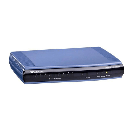
MediaPack Series Installing the MP-11x Series This subsection describes the MP-11x hardware installation. 2.1.1 Physical Description The subsections below provide a physical description of the front and rear panels of the MP-11x. 2.1.1.1 MP-11x Front Panel The device's front panel provides LEDs for indicating various operating statuses. The figure below displays the front panel of the MP-118. -
Page 11: Unpacking And Checking Package Contents
• Small plastic bag containing four anti-slide bumpers for desktop installation. Check, retain, and process any documents. Notify AudioCodes or your local supplier of any damage or discrepancies. 2.1.3 Mounting the MP-11x The device can be mounted in one of the following ways: Desktop mounting (refer to 'Desktop Mounting' on page 12). -
Page 12: Desktop Mounting
MediaPack Series The figure below shows the mounting components on the underside of the MP-11x: Figure 2-3: View of MP-11x Underside Table 2-2: Mounting Components on MP-11x Underside Item # Functionality Square slot used to attach anti-slide bumpers (for desktop mounting). Oval notch used to attach the MP-11x to a wall. -
Page 13: 19-Inch Rack Mounting
2.1.3.3 19-inch Rack Mounting The MP-11x can be installed in a standard 19-inch rack by placing it on an AudioCodes' 19- inch rack-mounting shelf (special customer order) that must be pre-installed in a rack. The shelf can hold up to two MP-11x devices. The rack-mounting shelf can be ordered separately from AudioCodes. -
Page 14: Cabling The Mp-11X
MediaPack Series 2.1.4 Cabling the MP-11x This section describes MP-11x cabling. To cable the MP-11x, take these steps: Connect MP-11x to the Ethernet network (refer to 'Connecting MP-11x to the Network' on page 14). Connect MP-11x to FXS/FXO devices (refer to 'Connecting MP-11x to FXS /FXO Devices' on page 14). -
Page 15: Connecting Mp-11X To Fxs/Fxo Devices
Installation Manual 2. Installing the Device 2.1.4.2 Connecting MP-11x to FXS/FXO Devices Follow the procedure below for connecting MP-11x to FXO or FXS interfaces. Warnings: • Ensure that you connect FXS ports only to analog telephones or PBX trunk lines, and FXO ports only to CO/PBX lines, otherwise damage to MP-11x can occur. -
Page 16: Connecting Mp-11X Rs-232 Port To A Pc
MediaPack Series The Lifeline’s splitter connects pins #1 and #4 to another source of an FXS port, and pins #2 and #3 to the POTS phone. Refer to the Lifeline splitter pinouts in the figure below: Figure 2-8: RJ-11 Lifeline Splitter Connector Pinouts To cable the MP-11x/FXS Lifeline, take these 3 steps: Connect the Lifeline splitter to Port #1 on MP-11x (the Lifeline splitter is a special order option). -
Page 17: Connecting Mp-11X To Power
Installation Manual 2. Installing the Device To connect MP-11x to a PC, take these 2 steps: Connect the PS/2 connector (refer to the figure below for connector pinouts) on one end of the cable to the MP-11x RS-232 port (labeled RS-232). Connect the DB-9 connector at the other end of the cable to either the COM1 or COM2 RS-232 communication port on your PC. -
Page 18: Installing Mp-124
MediaPack Series Installing MP-124 This subsection describes the MP-124 hardware installation. 2.2.1 Physical Description The subsections below provide a physical description of the MP-124 front and rear panels. 2.2.1.1 MP-124 Front Panel The MP-124 front panel (shown in the figure below) provides LEDs for indicating various operating statuses. -
Page 19: Mp-124 Rear Panel
Installation Manual 2. Installing the Device 2.2.1.2 MP-124 Rear Panel The device's rear panel (shown in the figure below) provides the ports for cabling the device to the various interfaces. Figure 2-11: MP-124 Rear Panel - AC Power Model Figure 2-12: MP-124 Rear Panel - DC Power Model The table below describes the MP-124 rear panel components. -
Page 20: Unpacking And Checking Package Contents
Two short equal-length brackets and bracket-to-device screws for 19-inch rack installation Check, retain and process any documents. Notify AudioCodes or your local supplier of any damage or discrepancies. 2.2.3 Mounting the MP-124 The MP-124 can be mounted in one of the following ways: Desktop mounting (refer to 'Desktop Mounting' on page 20). -
Page 21: 19-Inch Rack Mounting
Installation Manual 2. Installing the Device 2.2.3.2 19-inch Rack Mounting The MP-124 can be installed in a standard 19-inch rack, by using two short, equal-length brackets (supplied). The MP-124 with attached brackets for rack installation is shown in the figure below: Figure 2-14: MP-124 with Brackets for Rack Installation Rack Mount Safety Instructions When installing the chassis in a rack, implement the following safety... -
Page 22: Cabling The Mp-124
MediaPack Series Swivel the bracket until the holes in the bracket align with the two empty screw holes on the MP-124. Use the supplied screws to attach the bracket to the side of the MP-124. Repeat steps 1 through 4 to attach the second bracket to the other side of the MP-124. Position the MP-124 in the rack and line up the bracket holes with the rack frame holes. -
Page 23: Figure 2-15: Mp-124 Wiring Using Earthing Screw On Rear Panel
Installation Manual 2. Installing the Device AudioCodes recommends using a surge protector such as CIRCA 4B1FS-240 of CircaTelecom (http://www.circatelecom.com) and a building entrance terminal fixture (e.g., CIRCA 2625QC/QC). Alternative surge protectors should meet the following specifications: Technology: Solid State Breaking Voltage: 230V Response Time: <... -
Page 24: Connecting Mp-124 To The Ethernet Network
MediaPack Series If the MP-124 does not provide an earthing screw, then connect the surge protector to the grounding pin of the standard electrical outlet located alongside the power outlet that is powering MP-124 (see figure below). The wire used for this must be less than two meters in length with a minimum of 16 AWG. -
Page 25: Connecting Mp-124 To Fxs Interface
Installation Manual 2. Installing the Device 2.2.4.3 Connecting MP-124 to FXS Interface The MP-124 interfaces with the analog telephone interfaces by connecting to a main distribution frame (MDF), using a 50-pin Telco cable. MP-124 Safety Notice To protect against electrical shock and fire, use a 26 AWG min wire to connect analog FXS lines to the 50-pin Telco connector. -
Page 26: Figure 2-19: Mp-124 In A 19-Inch Rack With Mdf Adaptor
MediaPack Series Connect the wire-pairs at the other end of the cable to a male 50-pin Telco connector (not supplied). Insert and fasten the male connector to the female 50-pin Telco connector on the MP- 124 rear panel (labeled Analog FXS Lines 1-24). Connect the telephone lines from the MDF adaptor block to a fax machine, modem, or telephones by inserting each RJ-11 connector on the 2-wire line cords of the POTS phones into the RJ-11 sockets on the front of an MDF adaptor block, as shown in the... -
Page 27: Connecting Mp-124 Rs-232 Port To A Pc
Installation Manual 2. Installing the Device 2.2.4.4 Connecting MP-124 RS-232 Port to a PC Follow the procedure below to connect the MP-124 serial (RS-232) interface to a PC using a standard, straight-through cable with DB-9 connectors on either end. To connect MP-124 to a PC, take these 2 steps: Connect the DB-9 connector (refer to the figure below for connector pinouts) on one end of the cable to the MP-124 RS-232 port (labeled RS-232). -
Page 28: Figure 2-21: Wired Dc Power Terminal Block Connected To Mp-124
MediaPack Series 2.2.4.5.2 DC Power Supply The cabling of the MP-124 model for 48-VDC power supply. MP-124 DC Safety Notice When connecting MP-124 to a DC power supply, ensure that you adhere to the following safety guidelines: • Connect the device to a safety extra-low voltage (SELV) source that is sufficiently isolated from the mains. -
Page 29: Configuring The Device
Installation Manual 3. Configuring the Device Configuring the Device This section provides basic device configuration. This is performed mainly by using the device's embedded Web server (Web interface). Assigning an IP Address The device is supplied with application software (cmp file) residing on its flash memory. This software is set to factory default settings such as MAC and IP address, as listed in the table below. -
Page 30: Assigning An Ip Address Using Http
MediaPack Series 3.1.1 Assigning an IP Address Using HTTP You can assign an IP address to the device using the device's HTTP-based embedded Web server. To assign an IP address using HTTP, take these 7 steps: Disconnect the device from the network and reconnect it to a PC using one of the following methods: •... -
Page 31: Assigning An Ip Address Using Bootp
PC and re-access the device via the Web interface with its newly assigned IP address. 3.1.2 Assigning an IP Address Using BootP You can assign an IP address to the device using the supplied AudioCodes' BootP/TFTP Server application. Notes: •... -
Page 32: Assigning An Ip Address Using The Voice Menu Guidance
MediaPack Series In the ‘Gateway’ field, enter the IP address of the default gateway (if any). Click Apply to save the new client. Click OK; the ‘Client Configuration’ screen closes. Physically reset the device using the hardware reset button (or power down and then power up the device). - Page 33 Installation Manual 3. Configuring the Device To change the IP address: Press 1 followed by the pound key (#); The current IP address of the device is played. Press the # key. Dial the new IP address. Use the star (*) key instead of periods (.), e.g., 192*168*0*4, and then press # to finish.
-
Page 34: Table 3-2: Configuration File Name Patterns
Table 3-2: Configuration File Name Patterns Configuration File Name Pattern Description http://aa.bb.cc.dd/config.ini Standard config.ini. https://aa.bb.cc.dd/config.ini Secure HTTP. The device's MAC address is appended to the http://aa.bb.cc.dd/audiocodes/<MAC>.ini file name (e.g., http://36.44.0.6/audiocodes/00908f012300.ini). http://aa.bb.cc.dd:8080/config.ini HTTP on port 8080. http://aa.bb.cc.dd:1400/config.ini HTTP on port 1400. Generating configuration per IP/MAC address http://aa.bb.cc.dd/cgi-... -
Page 35: Assigning An Ip Address Using The Cli
Installation Manual 3. Configuring the Device Item Number at Description Menu Prompt or ini file parameter VoiceMenuPassword (refer to the User's Manual). 3.1.4 Assigning an IP Address Using the CLI The procedure below describes how to assign the device an IP address using the command-line interface (CLI). - Page 36 MediaPack Series Tip: Once the device is configured, backup your settings by saving the configuration (ini) file to your PC. This saved file can later be used, if necessary, to restore configuration settings (refer to 'Backing Up and Restoring Configuration' on page 39). To configure basic SIP parameters, take these 6 steps: Access the Web interface.
-
Page 37: Example Of Enabling Channels And Configuring Call Routing
Installation Manual 3. Configuring the Device Example of Enabling Channels and Configuring Call Routing This section provides an example for enabling the device's channels and for configuring Tel (PSTN) to IP call routing. This includes assigning the channels a telephone number and routing calls (with a dialed number of 10 as its prefix) made from these channels to a specific IP destination (e.g., IP address 10.33.24.14). -
Page 38: Figure 3-5: Connecting Two Devices
MediaPack Series The following figure shows an example of a configuration setup of two communicating FXS devices. Phones ‘101’ and '102' are connected to the first two channels of device with IP address 10.33.24.18; phone ‘120’ is connected to the first channel of device 10.33.24.14. The configuration in the 'Endpoint Phone Number Table' and 'Tel to IP Routing' pages (refer to the figure below) enables calls to be made between these two devices as well as between phones connected to the same device. -
Page 39: Saving And Resetting The Device
Installation Manual 3. Configuring the Device Saving and Resetting the Device To apply configuration changes to the device's volatile memory (RAM), click the Submit button located on the page in which you are configuring. Modifications to parameters with on-the-fly capabilities are immediately applied to the device; other parameters are applied only after a device reset. -
Page 40: Backing Up And Restoring Configuration
MediaPack Series Backing Up and Restoring Configuration The 'Configuration File' page enables you to save a copy of the device's current configuration as an ini file to a PC. This is useful for backing up your configuration. The saved ini file includes only those parameters that were modified as well as parameters with other than default values. -
Page 41: Changing The Login User Name And Password
Installation Manual 3. Configuring the Device Changing the Login User Name and Password To prevent unauthorized access to the Web interface, two Web user accounts (login accounts) are available (primary and secondary) with assigned user name and password. For detailed information on the Web user accounts, refer to the device's User’s Manual. To change the user name and password, take these 3 steps: Open the 'Web User Accounts' page (Configuration tab >... -
Page 42: Restoring Factory Default Settings
MediaPack Series Restoring Factory Default Settings You can use the device's hardware Reset button to restore all the device's configuration settings to factory defaults, including the device's IP address and Web interface's login user name and password. These default settings include factory defaults as well as user-defined defaults (refer to the device's User's Manual) defaults. -
Page 43: Upgrading Firmware Using Software Update Wizard
Installation Manual 3. Configuring the Device 3.8.1 Upgrading Firmware Using Software Update Wizard The Software Update Wizard guides you through the process of software upgrade -- selecting files and loading them to the device. The wizard is used specifically for loading the latest cmp file to the device. -
Page 44: Figure 3-10: Load Cmp File Wizard Page
MediaPack Series Click the Start Software Update button; the 'Load a CMP file' Wizard page appears: Figure 3-10: Load CMP File Wizard Page Note: At this stage, you can quit the wizard, by clicking Cancel without requiring a device reset. However, once you start uploading the cmp file, the process must be followed through and completed with a device reset. -
Page 45: Figure 3-11: Cmp Successfully Loaded Wizard Page
Installation Manual 3. Configuring the Device Click the Browse button, navigate to the cmp file, and then click Send File; the cmp file is loaded to the device and you're notified as to a successful loading, as shown below. Figure 3-11: CMP Successfully Loaded Wizard Page Click one of the following buttons: •... -
Page 46: Figure 3-12: End Process Wizard Page
MediaPack Series You can now choose to either: • Click Reset; the device resets, utilizing the new cmp and ini file you loaded up to now as well as utilizing the other auxiliary files. • Click Back; the 'Load a cmp file' page is opened again. •... -
Page 47: Upgrading The Ini And Auxiliary Files
Installation Manual 3. Configuring the Device 3.8.2 Upgrading the ini and Auxiliary Files The auxiliary files (and ini file) are dat files that can be loaded to the device to provide enhanced device provisioning. These files are described in the table below. For detailed information on these files, refer to the Product Reference Manual. -
Page 48: Figure 3-13: Load Auxiliary Files Page
MediaPack Series To load an auxiliary file to the device, take these 4 steps: Open the 'Load Auxiliary Files' page (Management tab >Software Update menu > Load Auxiliary Files). Figure 3-13: Load Auxiliary Files Page Click the Browse button corresponding to the file type that you want to load, navigate to the folder in which the file is located, and then click Open;... -
Page 49: Monitoring The Device
Installation Manual 4. Monitoring the Device Monitoring the Device The operating status of the device can be monitored in the following ways: Monitoring the device's hardware front-panel LEDs (refer to 'Monitoring Front-Panel LEDs' on page 49). Monitoring the device using the the Web interface's 'Home' page (refer to 'Monitoring Using the Web Interface' on page 50). -
Page 50: Web Interface's Home Page
MediaPack Series Label Type Color State Function Control Link Blinking Sending and receiving SIP messages. Control Green No traffic. Data Packet Green Blinking Transmitting RTP packets. Status Blinking Receiving RTP packets. No traffic. Channels Telephone Green Off-hook or ringing. Interface Line malfunction. -
Page 51: Viewing Channel Status
Installation Manual 4. Monitoring the Device 4.2.2 Viewing Channel Status The 'Home' page displays channel port icons that indicate the voice channels' operating status. You can use these port icons to drill down to view detailed channel status. For a detailed description of the 'Home' page, refer to the device's User's Manual. - Page 52 Installation Manual Version 5.6 www.audiocodes.com...
Need help?
Do you have a question about the MediaPack MP-11x Series and is the answer not in the manual?
Questions and answers