Table of Contents
Advertisement
Advertisement
Chapters
Table of Contents

Related Manuals for Brother LX-200


Summary of Contents for Brother LX-200
- Page 1 SERVICE MANUAL MODEL: LX-200/LX-900/LX-910D REVISED EDITION May, 2000...
- Page 2 Unauthorized copying of all or part of the contents of this manual is prohibited. The contents of this manual may change without notice.
- Page 3 INTRODUCTION This Service Manual describes the Cool Laminator LX-200/900/910D specifications, operating principles of the mechanisms, disassembly and reassembly procedures, and maintenance and troubleshooting procedures. This Service Manual is intended for use by trained technicians. It is not intended for use by the user.
- Page 4 Chapter 1. SPECIFICATIONS...
- Page 5 CONTENTS Chapter 1. SPECIFICATIONS 1.1 Mechanical Specifications....................1-1 1.1.1 Appearance ......................1-1 1.1.2 Operating Panel ....................1-1 1.1.3 Indicators....................... 1-2 1.2 Electrical Specifications ....................1-2 1.2.1 Power Supply ......................1-2...
-
Page 6: Mechanical Specifications
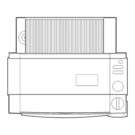
1.1 Mechanical Specifications 1.1.1 Appearance [1] External dimensions (W x D x H) 357 mm x 293 mm x 195 mm [2] Mass Approx. 4.6 kg (main unit only) 357 mm 195 mm 293 mm Fig. 1.1-1 Appearance 1.1.2 Operating Panel [1] Number of Keys 5 ( Power switch, Cut key, Feed key, Start/Stop button, Cutting mode selector) -
Page 7: Indicators
1.1.3 Indicators [1] Positions Start/Stop button LED indicators (red, green, orange) 1.2 Electrical Specifications 1.2.1 Power Supply [1] Power supply Commercial power supply (locally available power supply). Converted to DC by the AC adaptor. -
Page 8: Mechanisms
Chapter 2. MECHANISMS... -
Page 9: Table Of Contents
CONTENTS Chapter 2. MECHANISMS 2.1 Mechanical Operating Principles ..................2-1 2.1.1 Description of Mechanisms (Border Mode) ............2-1 2.1.2 Feed and Compression Mechanisms ..............2-2 2.1.3 Cutter Mechanism (Border Mode) ................ 2-4 2.1.4 Paper Size Detector Mechanism ................2-6 2.1.5 Trimming Mechanism ................... -
Page 10: Mechanical Operating Principles
2.1 Mechanical Operating Principles 2.1.1 Description of Mechanisms (Border Mode) 1. When a document is inserted into the paper loading gate, the paper feed rollers feed it to the driving roller. 2. As the document passes between the paper feed rollers, the paper size detector determines its size (length and width). -
Page 11: Feed And Compression Mechanisms
2.1.2 Feed and Compression Mechanisms The feed and compression mechanism controls the motor drive to feed the document into the film cartridge, compression-feed the films, and eject the laminated document. When no compression-feed is applied while feeding a document into the film cartridge or ejecting a laminated document, the LF motor rotates clockwise and the motor drive is transmitted via gears to the paper feed roller and paper eject roller. - Page 12 Operation During Film Compression-Feed 1. When the leading edge of the document enters the compression-feed area, LF motor starts to rotate counterclockwise, as indicated by the arrow. 2. Planet gear (A), which had been free, moves to engage with drive gear (A). The drive from the LF motor is then transmitted to the various gears, as shown in the diagram, and the driving roller rotates as indicated by the arrow.
-
Page 13: Cutter Mechanism (Border Mode)
2.1.3 Cutter Mechanism (Border Mode) The cutter mechanism cuts the laminated document to the size of the document plus an added border. Both edges of the films are cut to suit the width of the document and the leading edge and trailing edge are cut according to the document length. Y-Cutter Vertical Drive Operation 1. - Page 14 Cutting Leading and Trailing Edges (X-cutter Mechanism) 1. All the rollers which feed the document stop when the cut position at the leading edge of the document reaches the cutting position of the rotary cutter and fixed- blade cutter. 2. The DC motor rotates to drive the carriage in the X-cutter assembly via the spiral mechanism (not illustrated).
-
Page 15: Paper Size Detector Mechanism
2.1.4 Paper Size Detector Mechanism Paper Length Detection 1. When the leading edge of the document passes between the paper feed rollers, it rotates the paper sensor crank about the pivot to turn on the paper sensor which detects the document leading edge. 2. - Page 16 Paper Width Detection 1. The Y-cutter arm L (sensor unit) moves in the direction of the arrow. When the PL detect lever touches the document, it rotates about the pivot to switch off the photosensor. 2. When the photosensor turns off, the Y-cutter arm L movement stops and this position is detected as the document width.
-
Page 17: Trimming Mechanism
2.1.5 Trimming Mechanism 1. When a corner of the laminated document is inserted over the T-cutter plate, the sensor lever operates a leaf switch that detects the document. 2. When the document is detected, the motor gear of TC motor rotates in the direction of the arrow (counterclockwise) from its reference position to drive the T-cam gear in the direction indicated by the arrow (clockwise) via a series of gears. -
Page 18: Disassembly Procedures
Chapter 3. DISASSEMBLY PROCEDURES... - Page 19 CONTENTS Chapter 3. DISASSEMBLY PROCEDURES 3.1 Safety Precautions ......................3-1 3.2 Removing the Film Cartridge .................... 3-1 3.3 Covers ..........................3-2 3.3.1 Removing the Trimmer Upper Cover ..............3-2 3.3.2 Removing the Top Cover ..................3-3 3.3.3 Removing the Sub-tray ..................3-4 3.3.4 Removing the Paper Tray and Paper Guide............
- Page 20 3.10 Paper Eject Roller ......................3-28 3.10.1 Removing the Y-D Shaft ..................3-28 3.10.2 Removing the Paper Eject Sub-roller Unit............3-29 3.10.3 Removing the Paper Eject Roller Unit ..............3-29 3.11 Y-diversion Lever ......................3-30 3.11.1 Removing the Y-diversion Lever Assy..............3-30 3.11.2 Disassembling the Y-diversion Lever Assy ............
-
Page 21: Safety Precautions
3.1 Safety Precautions When conducting disassembly operations, place the unit on a grounded anti-static sheet. LSI and other electronic components are sensitive to static electricity and may be damaged if touched while charged. Before transporting a circuit board, wrap it in a conducting sheet such as aluminum foil. -
Page 22: Covers
3.Lift up the roller holder assy and pull out the film cartridge. Roller holder assy Film cartridge Fig. 3.2-2 Removing the Film Cartridge 2 3.3 Covers 3.3.1 Removing the Trimmer Upper Cover 1.Pull out the T-cutter plate and the trimmer bottom cover. T-cutter plate Trimmer bottom cover Fig. -
Page 23: Removing The Top Cover
2.Set the unit on its side with the trimmer cover uppermost. Remove the two trimmer cover screws. Remove the trimmer upper cover. Trimmer upper cover Trimmer cover screws Fig. 3.3-2 Removing the Trimmer Upper Cover 2 3.3.2 Removing the Top Cover Open the top cover. -
Page 24: Removing The Sub-Tray
3.3.3 Removing the Sub-tray 1.Open the sub-tray. 2.Flex the center of the sub-tray toward you to release the shafts from the shaft recesses in the body cover. Remove the sub-tray. Shaft recesses Sub-tray Body cover Fig. 3.3-4 Removing the Sub-tray 3.3.4 Removing the Paper Tray and Paper Guide 1.Lift the top of the paper tray in the direction of arrow A, then pull it in the direction... -
Page 25: Removing The Body Cover B
2.Disengage the paper guide hook (at the rear of the paper tray) from the paper tray. Remove the paper guide. Paper tray Hook Paper tray film Paper guide Fig. 3.3-6 Removing the Paper Guide 3.3.5 Removing the Body Cover B 1.Remove the two bottom cover screws A from the bottom of the bottom cover. - Page 26 2.Lift the rear of the bottom cover in the direction of arrow B while pushing it in the direction of arrow A. Release the four hooks at the rear face. 3.Push the body cover in the directions indicated by the arrows C to release the hook at the left and right side.
-
Page 27: Removing The Front Cover
3.3.6 Removing the Front Cover 1.Remove the two front cover screws under the bottom cover. Hook Front cover screws Fig. 3.3-10 Removing the Front Cover (1) 2.While pressing up the two hooks on the front cover from underneath, pull the front cover out to remove it. -
Page 28: Removing The Cover Switch Assy
3.3.7 Removing the Cover Switch Assy 1.Disconnect the cover switch assy harness connector (yellow CN4) located under the body cover from the switch PCB. 2.Remove the cover switch screw. Remove the cover switch assy. Cover switch assy Front Cover switch screw Harness connector Fig. -
Page 29: Removing The Dial Switch Holder Assy B
3.3.8 Removing the Dial Switch Holder Assy B 1.Disconnect the leaf switch R assy (red CN2) and leaf switch L assy (white CN3) harness connectors from the switch PCB. 2.Remove the dial lock arm and the dial lock arm spring that is hooked on the body cover. -
Page 30: Disassembling The Dial Switch Holder Assy B
3.3.9 Disassembling the Dial Switch Holder Assy B 1.Pull the plate spring in the direction of the arrow. Remove dial switch B. 2.Remove the two leaf switch R/L screws. Remove the leaf switch R assy (red CN2) and the leaf switch L assy (white CN3). Dial switch B Leaf switch R/L screws Leaf switch R/L assy’s... - Page 31 5.Remove the slide plate screw. Remove slide plate 2 from slide plate 1B. Slide plate screw Slide plate 2 Slide plate 1B Fig. 3.3-16 Disassembling the Dial Switch Holder Assy B (3) 6.Disconnect lug A on the dial lock arm from the dial switch holder. Pull the dial lock arm off the shaft.
-
Page 32: Chassis
3.4 Chassis 3.4.1 Removing the Harness Connectors Remove 12 harness connectors from the main PCB. Do not remove the power harness assy (red/black CN13). Power harness assy Fig. 3.4-1 Removing the Harness Connectors 3.4.2 Removing the PE Sensor Unit Open the bearing supports in the bottom cover outward. Lift the PE sensor unit out of the bottom cover bearing supports. -
Page 33: Removing The Chassis Unit
3.4.3 Removing the Chassis Unit 1.Remove the sensor frame screw from the sensor frame. Remove the ground wire (jack PCB). After removing the wire, reinsert the sensor frame screw to fasten the sensor frame to the chassis. Ground wire (jack PCB) Sensor frame Sensor frame screw Fig. - Page 34 3.Remove the cassette holder screws from under the chassis unit. Cassette holder screws Fig. 3.4-5 Removing the Chassis Unit (3) 4.Pull out the chassis unit. Chassis unit Fig. 3.4-6 Removing the Chassis Unit (4) 3-14...
-
Page 35: Pcbs
3.5 PCBs 3.5.1 Removing the Main PCB Assy 1.Disconnect the power harness assy (red/black CN13) from the Main PCB assy 1. 2.Remove the four main PCB screws. Remove the Main PCB assy 1. Main PCB screws Main PCB assy 1 Main PCB screws P ower harness assy Fig. -
Page 36: Removing The Switch Pcb Assy
3.5.3 Removing the Switch PCB Assy 1.Remove the two switch PCB screws A and three switch PCB screws B from under the body cover B. Remove the switch PCB assy 1. Switch PCB screws B Switch PCB screws A SW PCB assy 1 Fig. -
Page 37: T-Chassis
3.6 T-Chassis 3.6.1 Removing the T-Chassis Unit 1.Remove the plate spring screw. Remove the plate spring. 2.Remove the two T-chassis screws and remove the T-chassis unit. Plate spring screw T-chassis unit Plate spring T-chassis screw Fig. 3.6-1 Removing the T-Chassis Unit 3-17... -
Page 38: Disassembling The T-Chassis Unit
3.6.2 Disassembling the T-Chassis Unit 1.Open hook A on the T-paper guide in the direction A'. Pull out the T-lever shaft to remove the T-lever unit. 2.Remove T-lever 2 from T-lever 1. Remove the T-push spring and T-cam roller. 3.Remove the leaf switch TRI screw and remove the leaf switch TRI assy. 4.Disconnect the switch lever from the shaft hook on the T-paper guide and remove the switch lever. -
Page 39: Y-Ca Chassis
3.7 Y-CA Chassis 3.7.1 Removing the Y-CA Chassis Assy 1. Remove the Y-extension spring L. 2. Remove the two Y-CA chassis screws 3. Remove the Y-CA timing belt from the Y-cutter arm and remove the Y-CA chassis assy. Y-cutter arm Y-CA timing belt Y-extension spring L Y-CA chassis screws... -
Page 40: Disassembling The Y-Ca Chassis Assy
3.7.2 Disassembling the Y-CA Chassis Assy 1. Remove the pulley holder screw. Move the Y-CA pulley holder in the direction of arrow A and remove the Y-CA timing belt. 2. Move the Y-CA pulley holder in the direction of arrow B and remove it. 3. -
Page 41: Removing The Roller Holder Assy
3.7.3 Removing the Roller Holder Assy 1. Move the Y-cutter arm L as far as possible to the left. 2. Lift up the roller holder assy and remove the roller holder spring. 3. Remove the two roller holder rings. Push the roller holder assy to the right to disengage it from the chassis unit L boss shaft. -
Page 42: Disassembling The Roller Holder Assy
3.7.4 Disassembling the Roller Holder Assy 1. Disengage the two hooks A and remove the side covers L/R. 2. Remove the lock lever springs L/R from inside the lock levers L/R to allow the lock levers L/R to move freely. 3. -
Page 43: Sensor Frame And Y-Cutter Arm L
3.8 Sensor Frame and Y-cutter Arm L 3.8.1 Removing the Sensor Frame 1. Position the chassis unit as shown in the diagram. Remove the paper sensor crank from the paper feed roller. 2. Remove the two sensor frame screws. 3. Lift the right end of the sensor frame to release it from the top-right boss. Move the sensor frame to the left to release it from the two bosses at the left. -
Page 44: Disassembling The Sensor Frame
3.8.3 Disassembling the Sensor Frame 1. Disengage the hooks on FPC holder A from the cut-outs in the sensor frame. Move the FPC holder A in the direction of the arrow to remove it. 2. Release the FPC holder B from the boss hole in the sensor frame. Move the FPC holder B in the direction of the arrow to remove it. -
Page 45: Disassembling The Y-Cutter Arm L
3.8.4 Disassembling the Y-cutter Arm L 1. Remove the sensor holder screw. Remove the photosensor (PS) PCB holder from the Y-cutter arm L. 2. Disengage the PS PCB holder hook. Turn the PL detect lever to a position where it does not engage with the sensor, then remove it. -
Page 46: Paper Feed Roller
3.9 Paper Feed Roller 3.9.1 Removing the Paper Feed Sub-roller Assy 1. Position the chassis unit as shown in the diagram. Release the gear 16 hook from the paper feed sub-roller assy. Take care not to damage the gear hook by opening too far. -
Page 47: Removing The Paper Feed Roller Assy
3.9.2 Removing the Paper Feed Roller Assy 1. Position the chassis unit as shown in the diagram. Release the gear 16 hook from the paper feed sub-roller assy. Take care not to damage the gear hook by opening too far. 2. -
Page 48: Paper Eject Roller
3.10 Paper Eject Roller 3.10.1 Removing the Y-D Shaft 1. Remove the left and right paper eject sub-roller springs. 2. Remove the left and right Y-extension springs L/R. 3. Pull out the Y-gear 40-20 from the shaft and remove the Y-driving gear. Take care not to damage the gear hook by opening too far while removing the Y-gear 40-20. -
Page 49: Removing The Paper Eject Sub-Roller Unit
3.10.2 Removing the Paper Eject Sub-roller Unit 1. Remove the paper eject shaft holders L/R attached to the paper eject sub-roller unit by pulling them from the paper eject roller shaft in the direction of the arrow. 2. Remove the paper eject shaft holders L/R from the removed paper eject sub-roller unit. -
Page 50: Y-Diversion Lever
4. Push the paper eject roller unit to the left, then remove from the right. Paper eject roller unit Fig. 3.10-5 Removing the Paper Eject Roller Unit (2) 3.11 Y-diversion Lever 3.11.1 Removing the Y-diversion Lever Assy 1. Press the tabs on the two Y-cutter units in the direction of arrow 1 to release the hooks. -
Page 51: Disassembling The Y-Diversion Lever Assy
2. Lift up the right end and the left end of the Y-diversion lever assy in sequence to remove it. Y-diversion lever assy Fig. 3.11-2 Removing the Y-diversion Lever Assy (2) 3.11.2 Disassembling the Y-diversion Lever Assy 1. Release the two Y-cutter guide shaft rings from the right end. 2. -
Page 52: X-Cutter
3.12 X-cutter 3.12.1 Removing the X-cutter Unit 1. Remove the two X-cutter screws. Lift up the X-cutter unit. X-cutter unit X-cutter screws Fig. 3.12-1 Removing the X-cutter Unit 3.12.2 Disassembling the Tape Sensor Unit 1. Remove the leaf switch screw. Remove the leaf switch F assy. 2. -
Page 53: Driving Roller
3.13 Driving Roller Shaft 3.13.1 Removing the Driving Roller Shaft 1. Remove the driving roller C ring. Remove the gear 16M1 hook and driving roller bearing. Take care not to open the driving roller C ring too far. 2. Remove the driving roller E ring. Remove the driving roller bearing. 3. - Page 54 5. Gear 36/12 hook 6. Gear 21 7. Gear 37 hook 8. Gear 21 9. Gear 40/16 hook (This is removed when removing the paper eject roller.) 10. Gear 21 11. Gear 20 (This is removed when removing the paper eject roller.) 12.
-
Page 55: Disassembling The Left Side Of The Chassis
3.14.2 Disassembling the Left Side of the Chassis 1. Release roller guide L from the boss hole. Incline the guide and remove it. 2. Remove the LF motor screw and TC/LF motor screw. Remove the LF motor. Boss hole Roller guide L TC/LF motor screw LF motor LF motor screw... -
Page 56: Right Side Of The Chassis
3.15 Right Side of the Chassis 3.15.1 Disassembling the Right Side of the Chassis 1. Remove the leaf switch Y screw. Remove the leaf switch Y assy. 2. Release the Y-sensor lever hook and remove the Y-sensor lever. 3. Incline the edging saddle EDS-1 and remove it. 4. -
Page 57: Lower Chassis
7. Remove the two TC motor screws. Remove the TC motor. TC motor TC motor screws Fig. 3.15-2 Disassembling the Right Side of the Chassis (2) 3.16 Lower Chassis 3.16.1 Removing the Left and Right Sides of the Chassis Remove the six side chassis screws and remove the left and right sides of the chassis. Side chassis screws Fig. -
Page 58: Removing The Cassette Holder
3.16.2 Removing the Cassette Holder 1. Release the two side hooks fastening the cassette holder. 2. Flex the rear face of the cassette holder inward to release the two lugs. Remove the cassette holder from the bottom chassis. Hooks Cassette holder Bottom chassis Fig. -
Page 59: Removing The Cassette Detect Switch
3.16.4 Removing the Cassette Detect Switch Remove the leaf switch (SW) C screw. Remove the leaf switch C assy. Leaf switch (SW) C screw Leaf switch C assy Fig. 3.16-4 Removing the Cassette Detect Switch 3-39... - Page 60 Chapter 4. REASSEMBLY PROCEDURES...
- Page 61 CONTENTS Chapter 4. REASSEMBLY PROCEDURES 4.1 Safety Precautions ......................4-1 4.2 Table of Tightening Torque ....................4-1 4.3 Lower Chassis ........................4-2 4.3.1 Installing the Cassette Detect Switch..............4-2 4.3.2 Installing the Encoder (ENC) Sensor PCB ............4-2 4.3.3 Installing the Cassette Holder ................4-3 4.3.4 Installing the Left and Right Sides of the Chassis ..........
- Page 62 4.14 T-Chassis......................... 4-27 4.14.1 Reassembling the T-Chassis Unit............... 4-27 4.14.2 Installing the T-Chassis Unit ................4-28 4.15 PCBs..........................4-29 4.15.1 Installing the Switch PCB Assy ................4-29 4.15.2 Installing the Jack PCB Assy ................4-30 4.15.3 Installing the Main PCB Assy................4-30 4.16 Chassis ..........................
-
Page 63: Safety Precautions
4.1 Safety Precautions When conducting reassembly operations, place the unit on a grounded anti-static sheet. LSI and other electronic components are sensitive to static electricity and may be damaged if touched while charged. Before transporting a circuit board, wrap it in a conducting sheet such as aluminum foil. -
Page 64: Installing The Cassette Detect Switch
Name of Screw Qty. Screw Size Tightening Torque Page Leaf switch R/L screw PAN-HEAD MACHINE SCREW M2.6 0.196 to 0.392N•m 4-35 Dial holder screw 0.49 to 0.686N•m 4-35 TAPTITE,BIND B M3 Cover switch screw PHILLIPS PAN-HEAD TAPTILE B M2.6 0.49 to 0.686N•m 4-36 Front cover screw TAPTITE,BIND B M2.6X6... -
Page 65: Installing The Cassette Holder
4.3.3 Installing the Cassette Holder Engage the two side hooks and four claws on the cassette holder with the bottom chassis. Insert the two rear lugs into the slots to fasten the cassette holder. Cassette holder Slot Claws Hooks Bottom chassis Fig. -
Page 66: Right Side Of The Chassis
4.4 Right Side of the Chassis 4.4.1 Reassembling the Right Side of the Chassis 1. Attach the TC motor with the two TC/LF motor screws. TC motor TC/LF motor screws Fig. 4.4-1 Reassembling the Right Side of the Chassis (1) - Page 67 2. Put the TY-spring washer, TY-idle gear, and felt (stick onto the TY-idle gear) on the shaft. 3. Attach the TY-planet gear to the TY-planet gear holder. Put the TY-planet gear holder on the shaft and push it until the hooks engage. 4.
-
Page 68: Left Side Of The Chassis
4.5 Left Side of the Chassis 4.5.1 Reassembling the Left Side of the Chassis 1. Fasten the LF motor with one TC/LF motor screw and one LF motor screw. 2. Incline the roller guide L. Insert the cut-out into chassis L and push it into place until the hooks engage in the boss hole. - Page 69 13. Gear 21 14. Gear 37 hook 15. Gear 21 16. Gear 36/12 hook 17. Planet 20 hook (two) Attach the TY-planet gear to the planet gear holder. Put the TY-spring washer, planet gear holder, felt (stick onto the TY-planet gear holder), and planet 20 hook on the shaft.
- Page 70 Gear 25 hook Gear 60/20 hook Gear 60/16M1 Gear 36/12 hook Gear 16M1 Gear 20 Gear 50 Gear 40/16 hook Gear 60/16 Gear 21 Gear 36/12 hook TY-planet gear Planet gear 20 hook Gear 20 Gear 48/24 TY-planet gear Gear 37 hook TY-idle gear TY-planet gear Fig.
-
Page 71: Driving Roller Shaft
4.6 Driving Roller Shaft 4.6.1 Installing the Driving Roller Shaft 1. Insert the semicircular end of the driving roller shaft into the hole in chassis L. 2. Put the driving roller bearing from the left and attach it to chassis L. (Align the lug on the bearing with the cut-out in the chassis.) 3. -
Page 72: X-Cutter
4.7 X-cutter 4.7.1 Reassembling the Tape Sensor Unit 1. Fasten the leaf switch F assy to the tape sensor holder with the leaf switch screw. 2. Attach the tape sensor lever to the tape sensor holder. 3. Attach the tape sensor holder to the X-cutter unit with the sensor holder screw. X-cutter unit Tape sensor lever Tape sensor holder... -
Page 73: Y-Diversion Lever
4.8 Y-diversion Lever 4.8.1 Reassembling the Y-diversion Lever Assy 1. Hold the Y-cutter guide shaft with the two rings at the right end. Insert the left end into Y-cutter guide L and the right end into Y-cutter guide R. 2. Insert the Y-cutter guide shaft through the holes in the Y-diversion lever. Fasten with the two Y-cutter guide shaft rings. -
Page 74: Installing The Y-Diversion Lever Assy
4.8.2 Installing the Y-diversion Lever Assy 1. Mount the Y-diversion lever assy on the X-cutter unit by inserting the left end into chassis L then the right end into chassis R. Y-diversion lever assy X-cutter unit Fig. 4.8-2 Installing the Y-diversion Lever Assy 1 2. -
Page 75: Paper Eject Roller
4.9 Paper Eject Roller 4.9.1 Installing the Paper Eject Roller Unit 1. Temporarily remove gear 40-16 and gear 20 when installing the paper eject roller unit, as these can interfere with the installation. 2. Hold the paper eject roller unit with the end where the gears mount at the left. Insert the left end into the hole in chassis L, then the right end into the hole in chassis R. - Page 76 3. Insert the left and right paper eject roller bearings into the chassis L/R. The paper eject roller bearings can only be inserted if the lugs on the bearings are aligned with the grooves in the chassis. 4. Turn the paper eject roller bearing L counterclockwise to the boss hole to insert it in the chassis left side.
-
Page 77: Installing The Paper Eject Sub-Roller Unit
4.9.2 Installing the Paper Eject Sub-roller Unit 1. Orient the left paper eject shaft holder L (narrow) and right paper eject shaft holder R (wide) with the flat face inward and attach them to the paper eject sub-roller unit. 2. Attach the paper eject shaft holders L/R attached to paper eject sub-roller unit to the paper eject roller shaft in the chassis. - Page 78 2. Insert the Y-D shaft (with cams) first into chassis R, then into chassis L. The Y-D shaft should be inserted behind the paper eject shaft holders L/R. 3. Put the Y-driving gear onto the right semicircular end of the Y-D shaft. Next put the Y-gear 40-20 on this shaft and push the gear until the hook engages.
-
Page 79: Paper Feed Roller
4.10 Paper Feed Roller 4.10.1 Installing the Paper Feed Roller Assy 1. Insert the bearings into the chassis L/R. 2. Attach the left and right rod holders to the paper feed roller assy with the hooks inward. Bearings Paper feed roller assy Rod holders Fig. -
Page 80: Installing The Paper Feed Sub-Roller Assy
4.10.2 Installing the Paper Feed Sub-roller Assy 1. Hold the paper feed sub-roller assy with the semicircular end to the right. Push through the left and right rod holders and engage the paper feed roller grooves in the bearings. Paper feed sub-roller assy Bearings Rod holders Fig. -
Page 81: Sensor Frame And Y-Cutter Arm L
4.11 Sensor Frame and Y-cutter Arm L 4.11.1 Reassembling the Y-cutter Arm L 1. Fasten the Y-CA sensor to the photosensor (PS) PCB holder with the Y-CA sensor screw. 2. Put the PL detect lever on the photosensor (PS) PCB holder shaft. Turn the PL detect lever to the position where the sensor is cut off and push it until the hook engages. -
Page 82: Reassembling The Sensor Frame
4.11.2 Reassembling the Sensor Frame 1. Attach the paper sensor harness assy (flat cable) to the FPC holder A and FPC holder B. 2. Insert the hooks on FPC holder A into slots A in the sensor frame. Attach FPC holder A by moving it in the direction of the arrow until the hook tip engages in the groove. -
Page 83: Installing The Y-Cutter Arm L
4.11.3 Installing the Y-cutter Arm L 1. Engage the lug on Y-cutter guide L with the groove in Y-cutter arm L. Insert the Y- cutter arm shaft in Y-cutter arm L. 2. Insert the Y-cutter arm shaft in holes in the chassis L/R. Fasten with the two arm shaft rings. -
Page 84: Installing The Sensor Frame
4.11.4 Installing the Sensor Frame 1. Align the left end of the sensor frame with boss A on the side of chassis R. Align the right end of the sensor frame above boss B on chassis L. 2. Insert the paper sensor crank through the cut-out in the in the sensor crank protective film and engage it with the paper feed roller unit shaft. - Page 85 7. Put the interference board, set button L, and lock lever spring L onto the lock lever shaft. Pass the shaft through the hole in the left side of the roller holder assy. 8. Insert the lock lever shaft in the semicircular hole in lock lever R. Insert hook B of lock lever L from the position of cut-out A as with lock lever R, and turn to fasten in position.
-
Page 86: Installing The Roller Holder Assy
4.12.2 Installing the Roller Holder Assy 1. Move the Y-cutter arm L as far as possible to the left. 2. Insert the chassis unit R boss shaft into the hole in the roller holder assy, then insert the chassis unit L boss shaft. Attach the roller holder rings to the left and right boss shafts to fasten the roller holder assy in position. -
Page 87: Y-Ca Chassis
4.13 Y-CA Chassis 4.13.1 Reassembling the Y-CA Chassis Assy 1.Attach the Y-CA motor with the two Y-CA motor screws. 2.Put the Y-CA driving pulley on the Y-CA chassis shaft and fasten it with the Y-CA driving pulley ring. 3.Insert the shaft of the Y-CA idle pulley into slot A of the Y-CA pulley holder. Push the Y-CA idle pulley in the direction of arrow A to fasten it in position. -
Page 88: Installing The Y-Ca Chassis Assy
4.13.2 Installing the Y-CA Chassis Assy 1.Align the Y-CA chassis assy with the positioning hook and the two bosses on chassis Positioning hook Bosses Fig. 4.13-2 Installing the Y-CA Chassis Assy (1) 2.Attach the Y-CA timing belt to the attachment position on the Y-cutter arm L. 3.Fasten the Y-CA unit with the two Y-CA frame screws. -
Page 89: T-Chassis
4.14 T-Chassis 4.14.1 Reassembling the T-Chassis Unit 1.Install the T-idle gear and T-gear 35-14 on the T-chassis. Put the T-cam shaft through the T-cam gear and engage the hook on the T-cam gear with the groove on the T- cam shaft. 2.Align the T-sensor lever with boss hole A. -
Page 90: Installing The T-Chassis Unit
4.14.2 Installing the T-Chassis Unit 1.Align the T-chassis unit with the two bosses. Bosses T-chassis unit Fig. 4.14-2 Installing the T-Chassis (1) 2.Fasten the T-chassis unit with the two T-chassis screws. 3.Align the plate spring with the boss and fasten it with the plate spring screw, such that it holds T-gear 35-14 in position. -
Page 91: Pcbs
4.15 PCBs 4.15.1 .Installing the Switch PCB Assy 1.Turn the body cover upside-down, and attach the start switch B,start key film, start key actuator, two-connection switch, and power switch. Two connection switch Power switch Start key actuator Start key film Start switch B ig. -
Page 92: Installing The Jack Pcb Assy
4.15.2 Installing the Jack PCB Assy Align the jack PCB assy 1 with the boss and fasten it in position with the jack PCB screw. Jack PCB screw Ferrite core Jack PCB assy 1 Boss Fig. 4.15-3 Installing the Jack PCB Assy 4.15.3 Installing the Main PCB Assy 1.Align the Main PCB assy 1 with the two bosses and fasten it in position with the four main PCB screws. -
Page 93: Chassis
4.16 Chassis 4.16.1 Installing the Chassis Unit 1.Align the chassis unit with the two bosses on the bottom cover and fasten it in position with the four cassette holder screws. cassette holder screws Fig. 4.16-1 Installing the Chassis Unit (1) 2.Attach the chassis unit using the two bottom cover screws B and the spring washers in the bottom cover. -
Page 94: Installing The Pe Sensor Unit
3.Remove the sensor frame screw from the sensor frame. Attach the ground wire and fasten it with the sensor frame screw. Ground wire Sensor frame Sensor frame screw Fig. 4.16-3 Installing the Chassis Unit (3) 4.16.2 Installing the PE Sensor Unit 1.Engage the tip of the PE sensor unit with the paper sensor crank. -
Page 95: Installing The Harness Connectors
4.16.3 Installing the Harness Connectors Attach the 12 harness connectors to the MAIN PCB. Do not attach the power harness assy (red/ black CN13). Orange (CN15) Blue (CN8) White (CN7) Red (CN6) Power harness assembly Black (CN5) Yellow (CN12) Yellow, blue, white, red, gray (CN11) Flat cable Black (CN10) White (CN3) - Page 96 2.Align slide plate 2 with the boss on slide plate 1B and fasten it with the slide plate screw. Slide plate screw Slide plate 2 Slide plate 1B Bosses Fig. 4.17-2 Reassembling the Dial Switch Holder Assy B (2) 3.Engage the slide plate 1B hook and bosses A with the slots in the dial S holder assy. Ensure that slide plate 1B is positioned relative to the dial lock arm as shown in detail A.
-
Page 97: Installing The Dial Switch Holder Assy B
5.Align the leaf switch R assy (red CN2) and the leaf switch L assy (white CN3) with the boss holes and fasten them in position with the two leaf switch R/L screws. 6.Pull the plate spring in the direction of the arrow. Insert the dial switch B such that the indicator is positioned between the two leaf switches. -
Page 98: Installing The Cover Switch Assy
4.17.3 Installing the Cover Switch Assy 1.Align the cover switch assy with the boss hole and fasten it in position with the cover switch screw. 2.Connect the cover switch unit harness connector (yellow CN4) to the switch PCB. Cover switch assy Front Cover switch screw Boss hole... -
Page 99: Installing The
4.17.4 Installing the Front Cover 1.Align the front cover with the angle of the cover front face and insert parts A into parts B. Push until the hooks at each side of the front cover engage. Parts B Front cover Parts A Fig. -
Page 100: Installing The Body Cover
4.17.5 Installing the Body Cover 1.Pass all the harnesses through the hooks in the bottom cover. Fig. 4.17-9 Installing the Body Cover (1) 2.Connect the switch harness assy (white CN1) to the MAIN PCB. Switch harness assy Fig. 4.17-10 Installing the Body Cover (2) 4-38... - Page 101 3.Insert the lug on the Y-cutter guide R into the slot in the dial switch holder assy. Dial switch holder assy Slot Y-cutter guide R Fig. 4.17-11 Installing the Body Cover (3) 4.Engage the two hooks on the body cover front face. 5.Push down the body cover sides to engage the two hooks.
- Page 102 7.Insert the two bottom cover screws A from underneath to fasten the body cover in position. Bottom cover screws A Fig. 4.17-13 Installing the Body Cover (5) 4-40...
-
Page 103: Installing The Paper Tray And Paper Guide
4.17.6 Installing the Paper Tray and Paper Guide 1.Press the paper guide hook (at the rear of the paper tray) into the groove in the paper tray. Paper tray Hook Paper tray film Groove Paper guide Fig. 4.17-14 Installing the Paper Guide 2.Push the paper tray in the direction of arrow A until its edge reaches the paper feed roller. -
Page 104: Installing The Sub-Tray
4.17.7 Installing the Sub-tray Flex the center of the sub-tray toward you to insert the shafts into the shaft recesses in the body cover. The sub-tray can be folded in the direction of the arrow. Sub-tray Shaft recesses Body cover Fig. -
Page 105: Installing The Trimmer Upper Cover
4.17.9 Installing the Trimmer Upper Cover 1.Set the unit on its side with the trimmer upper cover uppermost. 2.Engage part B of the trimmer upper cover with part A on the chassis. Align the trimmer cover with the two bosses and fasten it in position with the two trimmer cover screws. -
Page 106: Installing The Film Cartridge
4.18 Installing the Film Cartridge 1.Insert the film cartridge with the arrow mark facing forward. Lower it into the roller holder assy. Roller holder assy Film cartridge Fig. 4.18-1 Installing the Film Cartridge (1) 2.Push the left and right set buttons to lock the roller holder assy in position. Close the top cover. - Page 107 Chapter 5. ELECTRONIC CONTROLLERS...
- Page 108 CONTENTS Chapter 5. ELECTRONIC CONTROLLERS 5.1 Electronic Parts....................... 5-1 5.1.1 Configuration of the Electronic Parts ..............5-1 5.1.2 Outline of the Electronic Parts ................5-2 5.2 Operation of Each Part ....................5-3 5.3 Main PCB........................5-4 5.4 Detector Circuits ......................5-9 5.5 Motor Drive Circuits ......................
-
Page 109: Electronic Parts
5.1 Electronic Parts 5.1.1 Configuration of the Electronic Parts The electronic parts of the unit comprise the following PCBs and an AC adaptor. Main PCB Switch PCB Jack PCB Paper size sensor PCB Film detector PCB AC adaptor Film Detect Side Cutter Paper Detect Corner Cutter... -
Page 110: Outline Of The Electronic Parts
5.1.2 Outline of the Electronic Parts Each PCB and the AC adaptor are described below. Main PCB The main PCB is located below the paper guide. It is connected to all PCBs, motors, switches, and cables. It converts the unstabilized DC voltages input from the Jack PCB to stabilized +5V and +24V DC voltages, which are supplied to all controllers. -
Page 111: Operation Of Each Part
5.2 Operation of Each Part This unit is operated by three 24 V stepping motors and one DC motor (for the X-cutter unit). The operation of each motor shown in Fig. 5.1-1 is described below. Paper feed motor (LF Motor) This motor is used to feed the document and film and to eject the laminated document. -
Page 112: Main Pcb
5.3 Main PCB Fig. 5.3-1 shows a block diagram of the electrical parts. The Main PCB comprises the CPU, detector circuits (including switch status detection), motor drive circuits, and power circuits. Corner Cutter Motor (TC) Paper Size Detector Motor (Y-CA) Fig. - Page 113 Table 5.3-1 CPU I/O Map Port Pin No. YA MOTOR PHASE A YA MOTOR PHASE B YA MOTOR PHASE C YA MOTOR PHASE D DC-IN1 DC-IN2 DC-ENA DC-IL DVO (P13) BUZZER INT1 (P11) INT (COVER) COVER LED 4 LED 1 LED 2 LED 3 YCA-LED...
- Page 114 Port Pin No. CSEL A T/C MOTOR PHASE B T/C MOTOR PHASE A T/C MOTOR PHASE D T/C MOTOR PHASE C LF MOTOR PHASE B LF MOTOR PHASE A LF MOTOR PHASE D LF MOTOR PHASE C Clock Circuit The main CPU incorporates a clock-generation circuit which uses externally mounted components.
- Page 115 Buzzer Drive Circuit This circuit sounds the piezoelectric buzzer. To sound the buzzer, the main CPU outputs a 4 kHz squarewave with 50% duty from port DV0 (P13). This signal is used to generate the buzzer sound. To stop the buzzer, the port status is set to High level using R82 in the input mode. Fig.
- Page 116 Specification Switching Circuit This circuit reads the specification switching information. The specification switching is conducted by a ROM program built into the main CPU according to the solder point settings on the PCB. The relationships between the solder points and specifications are shown in PART LIST.
-
Page 117: Detector Circuits
5.4 Detector Circuits These circuits detect the status of the switches, keys and buttons that operate the machine (Power switch, Cut key, Feed key, Start/Stop button, and dial switches) and the sensors that determine the film type, document length and width, and cover open/closed status. - Page 118 Switch Scan Circuit This circuit in the main CPU scans the status of the Power switch, Cut button, Feed button, Start button, and TRI switch (leaf switch) at 14 ms intervals to continuously detect the status of each switch. The circuit comprises a matrix of two output ports (P36, P37) and four input ports (P40 to P43).
- Page 119 Dial Switch Circuit This circuit detects the automatic cutting mode selected on the Cutting mode selector switch. This circuit comprises two leaf switches (ON/OFF-R, ON/OFF-L ) mounted on each side of the dial switch. The signals detected by these two leaf switches are input to the Main PCB via the Switch PCB.
- Page 120 Paper Width Detector Circuit This circuit detects the width of the document and determines the Y-carriage position. It also determines the Y-carriage standby position when the power is ON or the cover is closed. This circuit comprises the transmissive photosensor YCA-F mounted on the Paper size detector PCB that is attached to the Y-carriage.
- Page 121 Cartridge Type Detector Circuit This circuit detects the type of film cartridge. The cartridge type detector switch CSIZE is mounted at the film cartridge inlet. When an A4 film cartridge is inserted, the film cartridge presses the cartridge type detector switch and sets the input Low (ON). When no cartridge or an A6 film cartridge is inserted, the input remains High (OFF).
- Page 122 Film Feed Detector Circuit This circuit detects the film feed status to prevent jams if a problem occurs. The film feed detector switch TPS is mounted before the paper eject roller and if there’s no problem with the film during document feed or compression, the film presses against the film feed detector switch TPS and sets the ON (input Low).
-
Page 123: Motor Drive Circuits
5.5 Motor Drive Circuits Paper Feed Motor Drive Circuit (LF Motor) This circuit drives the paper feed motor using 2-2 phase excitation from the +24V DC stabilized constant voltage. The stepping motor excitation phases A, B, C, and D are controlled by main CPU ports P72, P73, P70, and P71, respectively. - Page 124 Trimming Motor Start Point Detect Circuit This circuit rotates the trimming cam and Y-cutter cam forward and backward with the trimming motor (T/C motor) to detect the position of each cam. The trimming switch (TRG) is designed to turn OFF 150 steps before the trimming cam standby position (T-cutter top position).
- Page 125 X-cutter Motor Drive Circuit This circuit drives the DC motor with the +24V DC stabilized constant voltage. The X-cutter comprises a DC motor and two switches. The DC motor is controlled by the main CPU ports P14 to P17 and is driven by the DC motor control driver #4. The two switches are detected by ports P53 and P54.
-
Page 126: Power Supply Circuits
5.6 Power Supply Circuits The power supply circuits receive the unstabilized DC voltage supplied to CN1 from the AC adaptor through the Jack PCB via fuse F1 (protective circuit), diode D6, and the filter circuit. The 2-channel switching power IC (IC#6) in the circuits converts the unstabilized DC voltage into a stabilized +5V voltage (logic power supply) and into a stabilized +24V DC voltage (drive power supply). - Page 127 +5V Power Supply Fig. 5.6-2 shows the timing chart of the power IC (IC#6) for the +5V DC power supply during idling. In this circuit, the transistor Q11 switches at approximately 100 kHz to convert the unstabilized input voltage to a stabilized +5V supply. When transistor Q11 is ON, energy accumulates in the coil L3 and electrolytic capacitor C27 until they are able to supply a +5V voltage.
- Page 128 Chapter 6. MAINTENANCE...
- Page 129 CONTENTS Chapter 6. MAINTENANCE 6.1 Lubrication ......................... 6-1 6.1.1 Table of Lubricants ....................6-1 6.1.2 Precautions during Lubrication ................6-1 6.1.3 Lubrication Positions..................... 6-1 6.2 Replacing the Cartridge and Film ..................6-9 6.2.1 Replacing the Cartridge ..................6-9 6.2.2 Replacing the Sheet.................... 6-12 6.3 Adjustments........................
-
Page 130: Lubrication
6.1 Lubrication After the parts of 6.1.3 are replaced, apply lubricant to the positions indicated in 6.1.3 Lubrication Positions below. If only one of a pair of touching parts is replaced, lubricant remains on the other part and no further lubrication is required. If both of a pair of touching parts is replaced, lubricant must be applied to the indicated position. - Page 131 Chassis L LF motor Gear Planet gear 20 hook LF motor gear Planet gear 20 hook Fig. 6.1-2 Chassis L LF motor Gear Chassis R TC motor Gear TC motor gear TY-idle gear Fig. 6.1-3 Chassis R TC motor Gear...
- Page 132 Chassis L/R TY-planet Gear Holder TY-spring washer TY-idle gear TY-planet gear holder Felt TY-planet gear Fig. 6.1-4 Chassis L/R TY-planet Gear Holder Top of Chassis L/R Chassis Roller holder pin Lock pin Roller guide Fig. 6.1-5 Top of Chassis L/R...
- Page 133 Roller Holder (left and right) Roller holder return spring (right only) Roller holder Release plate Sub-roller bearing Fig. 6.1-6 Roller Holder Y-cutter Arm L Y-cutter arm L Sensor frame S (left and right) Y-cutter arm shaft S (left and right) Fig.
- Page 134 Paper Eject Roller Paper Eject Roller Paper eject roller bearing Paper eject roller unit Paper eject roller bearing Fig. 6.1-8 Paper Eject Roller Paper Eject Sub-roller Paper eject shaft holder L Paper eject sub-roller Paper eject shaft holder R Fig. 6.1-9 Paper Eject Sub-roller...
- Page 135 Driving Roller Bearing Driving roller shaft Bearing Fig. 6.1-10 Driving Roller T-Chassis Unit Plate spring T-chassis T-gear 35-14 Fig. 6.1-11 T-Chassis Unit...
-
Page 136: Dial Switch
Y-CA Chassis Assy Y-CA idle pulley Y-CA pulley holder Y-CA chassis Fig. 6.1-12 Y-CA Chassis Assy Dial Switch Dial switch B Dial S holder assembly Plate spring Fig. 6.1-13 Dial Switch... - Page 137 Y-Diversion Lever E (two positions) Y-cutter guide shaft Y-diversion lever assy Ring Fig. 6.1-14 Y-Diversion Lever...
-
Page 138: Replacing The Cartridge And Film
6.2 Replacing the Cartridge and Film 6.2.1 Replacing the Cartridge [1] Turn off the power switch and open the top cover. Fig. 6.2-1 Replacing the Cartridge (1/6) [2] Push the lock lever R in the direction of the arrow to unlock the roller holder assy. Hold the set buttons and lift out the roller holder assy. - Page 139 [3] Carefully remove the cartridge. Fig. 6.2-3 Replacing the Cartridge (3/6) [4] Orient the new cartridge with the arrow mark facing forward and carefully insert it. Check the following items before inserting the cartridge. Cartridge shutter is fully closed. The edge of the sheet is parallel with the cartridge film outlet. If the edge is not parallel, cut it parallel with scissors.
- Page 140 [5] Lower the roller holder assy and push the set buttons in the direction of the arrows to lock the roller holder assy in position. Fig. 6.2-5 Replacing the Cartridge (5/6) [6] Close the top cover. Fig. 6.2-6 Replacing the Cartridge (6/6) [7] Turn on the power switch and press the Feed button to feed out some sheet and remove the slackness in the sheet.
-
Page 141: Replacing The Sheet
6.2.2 Replacing the Sheet [1] Carefully remove the cartridge. Fig. 6.2-7 Replacing the Sheet (1/9) [2] Open the cartridge shutter, then open the cartridge cover. Fig. 6.2-8 Replacing the Sheet (2/9) 6-12... - Page 142 [3] Remove the old sheet. Fig. 6.2-9 Replacing the Sheet (3/9) [4] Hold the yellow plastic holders of the new sheet and insert the sheet in the cartridge as shown in the diagram. It is not possible to insert the sheet in the wrong direction. Fig.
- Page 143 [5] Close the cartridge cover, ensuring that the edge of the sheet protrudes from the cartridge film outlet. Fig. 6.2-11 Replacing the Sheet (5/9) [6] Press the shutter buttons and close the shutter. Fig. 6.2-12 Replacing the Sheet (6/9) 6-14...
- Page 144 [7] Press the catches on the yellow plastic holders and remove them in the sequence shown. Fig. 6.2-13 Replacing the Sheet (7/9) [8] Check that the edge of the sheet is parallel with the cartridge film outlet. If the edge is not parallel, cut it parallel with scissors.
- Page 145 [9] Orient the cartridge with the arrow mark facing forward and carefully insert it. Arrow mark Fig. 6.2-15 Replacing the Sheet (9/9) Note: After removing sheet from its sealed pack, it will dry up if not inserted into the cartridge. 6-16...
-
Page 146: Adjustments
6.3 Adjustments 6.3.1 Adjusting the Right Y-cutting Position (Border Mode) Loosen the screw and move slide plate 2 in the direction of the arrow indicated in the diagram below. This moves the Y-cutter attached to the Y-cutter guide and adjusts the cutting position for the right edge of the sheet. -
Page 147: Adjusting The Left Y-Cutting Position
6.3.2 Adjusting the Left Y-cutting Position Loosen the screw and move the photosensor (PS) PCB holder left or right. This moves the detection position of the sensor attached to the photosensor (PS) PCB holder and adjusts the cutting position for the left edge of the sheet. In the diagram below, move the photosensor (PS) PCB holder to the right to increase the border of the laminated document. -
Page 148: Adjusting Perpendicularity Of Chassis And Document
6.3.3 Adjusting Perpendicularity of Chassis and Document 1. Loosen the four screws under the bottom cover, as shown in the diagram. 2. Insert the Slant adjust plate between the paper feed roller and paper feed sub-roller until the edge of the gauge is near the fixed cutter. 3. -
Page 149: Quick Way To Clean X-Cutter
Quick way to clean X-cutter Here’s procedure for quick way to clean X-cutter. Note that this indicates only the way of cleaning, and If mal-cutting still persists after cleaning according the way below, then replacement of X-cutter unit according disassembly procedure of Chapter 3 is necessary. 1. - Page 150 3. Remove Paper eject sub-roller springs. Fig. 6.4-3 Removing Paper eject sub roller springs 4. Clean fixed blade of X-cutter by inserting alcohol-soaked cotton bar into clearance between Paper eject roller and Paper eject sub-roller and sliding it horizontally, along cleaning range indicated in the Fig.
- Page 151 Chapter 7. TROUBLESHOOTING...
- Page 152 CONTENTS Chapter 7. TROUBLESHOOTING 7.1 Outline ..........................7-1 7.2 Precautions during Repair....................7-1 7.3 After Making a Repair ....................... 7-1 7.4 Basic Checks........................7-1 7.5 Troubleshooting Flowcharts ....................7-2 7.6 Troubleshooting Tables..................... 7-5...
-
Page 153: Outline
7.1 Outline It is extremely difficult to determine when and where a problem may arise and to determine the cause of a problem that did arise. It is even more difficult to formulate remedies for theoretical problems which may or may not occur. This chapter gives examples of actual problems that have occurred, together with suggested remedies. -
Page 154: Troubleshooting Flowcharts
7.5 Troubleshooting Flowcharts AC adaptor plugged in, power ON Nothing happens when power switch is pressed. Is green LED indicator lit? a. Abnormal +5V DC supply. b. Defective main CPU. See page 7-5. Nothing happens when switches are pressed (LED indicators do not light). a. - Page 155 Abnormal trimming. Is trimming normal? a. Defective trimming (TRI) switch. b. Defective trimming (TC) motor. c. Defective trimming (TRG) switch. d. Defective T-cutter. See page 7-12. Nothing happens when switches are pressed Is X-cutter operation (LED indicators do not light). normal? a.
- Page 156 Problem during automatic operation. Document cannot be correctly inserted. Is document correctly inserted? a. Problem with input-side rollers. b. Defective PE sensor (P-END) switch. See page 7-16. Document width cannot be detected correctly. Document width a. Defective Y-carriage (Y-CA) motor. detected correctly? b.
-
Page 157: Troubleshooting Tables
7.6 Troubleshooting Tables Nothing happens when power switch is pressed. (LED indicator does not light.) a. Abnormal input voltage. b. Abnormal +5V DC supply. c. Defective main CPU. Problem Check Item Cause Remedy Repair Section a. Abnormal input Are AC adaptor, Jack PCB, Defective harness Connect harness voltage... - Page 158 Nothing happens when switches are pressed. a. Defective switch or leaf switch on the Switch PCB. b. Defective LED on the Switch PCB. Problem Check Item Cause Remedy Repair Section a. Defective Is Switch PCB correctly Defective Switch PCB Correctly mount switch or leaf mounted? mounting.
- Page 159 Problem Check Item Cause Remedy Repair Section b. Defective LED Low output from the main Defective main CPU#1. Replace Main PCB Replace 3.3.3 on the Switch CPU ports P32 to P35 (Pin assy. CPU#1. 3.3.4 35 to Pin 38) that drive 3.3.5 indicators LED1 to LED4? 3.5.1...
- Page 160 An error occurred during processing after power ON (before film feed). a. Abnormal +24V DC supply b. Abnormal DC input voltage. c. Abnormal X-cutter power ON processing. d. Abnormal Y-carriage power ON processing. e. Abnormal Y-cutter power ON processing. Problem Check Item Cause Remedy...
- Page 161 Problem Check Item Cause Remedy Repair Section d. Abnormal Y- Sensor lever cuts Deformed sensor frame Replace the sensor carriage power photosensor at start position? unit? frame unit. ON processing 3.3.3 Photosensor cut off when not Sensor lever incorrectly 3.3.4 at start position? installed.
- Page 162 An error occurred during processing after power ON (after film feed). a. Defective film or cartridge. b. Defective film feed detector (TPS) switch. c. Defective film feed system. Problem Check Item Cause Remedy Repair Section a. Defective film or Is the film cartridge correctly Defective film cartridge Correctly mount the cartridge...
- Page 163 Abnormal manual feed a. Defective film feed (LF) motor. b. Defective film compression system. c. Problem related to paper eject roller. Problem Check Item Cause Remedy Repair Section a. Defective film Is the black lead connector Motor harness assy not Correctly connect the 3.3.3 feed (LF) motor...
- Page 164 Abnormal trimming a. Defective trimming (TRI) switch. b. Defective trimming (TC) motor. c. Defective trimming (TRG) switch. d. Defective T-cutter. Problem Check Item Cause Remedy Repair Section a. Defective Is document correctly Document inserted Correctly insert the trimming (TRI) inserted? incorrectly.
- Page 165 Problem Check Item Cause Remedy Repair Section b. Defective Is the white lead connector Motor harness assy not Correctly connect the 3.3.3 trimming (TC) connected to CN9 on the connected. motor harness assy. 3.3.4 motor. Main PCB? 3.3.5 Are pulses output from output Defective main CPU#1.
- Page 166 Problem Check Item Cause Remedy Repair Section d. Defective T- Does the trimming T-cam Problem with planet Apply KS64F silicon 3.3.1 cutter. rotate when the trimming gear operation. grease to the four 3.3.3 motor (TC motor) rotates? bearings. 3.3.4 3.3.5 Replace the TY planet gear.
- Page 167 Abnormal X-cutter operation. a. Defective X-cutter position switch. b. Defective X-cutter DC motor. c. Defective X-cutter. Problem Check Item Cause Remedy Repair Section a. Defective X- The X-cutter rotary cutter is Defective X-cutter unit. Replace the X-cutter 3.3.1 cutter position at the left or right end but unit.
- Page 168 Document cannot be correctly inserted. a. Problem with input-side rollers. b. Defective PE sensor (P-END) switch. Problem Check Item Cause Remedy Repair Section a. Problem with Is document correctly Document inserted Correctly insert the input-side inserted against the paper incorrectly. document.
- Page 169 Document width cannot be detected correctly. a. Defective Y-carriage (Y-CA) motor. b. Defective sensor unit (YCA-F). c. Defective Y-cutter arm. Problem Check Item Cause Remedy Repair Section a. Defective Y- Is the Y-CA motor harness Motor harness not Correctly connect the 3.3.3 carriage (Y-CA) connected to connector C11...
- Page 170 Lamination is not normal. a. Defective film type (ENC) detector. b. Defective document or film. Problem Check Item Cause Remedy Repair Section a. Defective film Is the white lead connector Defective harness assy Correctly connect the 3.3.3 type (ENC) connected to CN3 on the connection.
- Page 171 No cutting in Y direction. a. Defective Y-cutter (Y-G) switch. b. Abnormal Y-cutter vertical movement. Problem Check Item Cause Remedy Repair Section a. Defective Y- Is the blue lead connector Leaf-switch assy not Correctly connect the 3.3.3 cutter (Y-G) connected to CN8 on the connected correctly.
- Page 172 Incorrect cutting in Y direction. a. Incorrect Y-direction cutting position. b. Defective Y-cutter. Problem Check Item Cause Remedy Repair Section a. Incorrect Y- Does the right cutter move Y-cutter guide R and Correctly reassemble direction cutting when the mode is changed? slide plate 2 incorrectly the body cover.
- Page 173 Incorrect cutting position at document front or rear edge. a. Defect in paper feed system. b. Defect in paper sensor system. Problem Check Item Cause Remedy Repair Section a. Defect in paper Do the three planet gear units Defective operation of Apply KS64F silicon 3.3.1 feed system...
- Page 174 Cartridge size, film type cannot be detected correctly. a. Defective cartridge type detector (CSIZE) switch. Problem Check Item Cause Remedy Repair Section a. Defective Is the yellow lead connector Leaf switch C assy not Correctly connect the 3.3.3 cartridge type connected to CN12 on the connected.
- Page 175 Buzzer does not sound. a. Defective buzzer circuit. Problem Check Item Cause Remedy Repair Section a. Defective Are 4kHz pulses output from Defective main CPU#1. Replace Main PCB Replace buzzer circuit DV0 (20 pin) on main assy. CPU#1. 3.3.3 CPU#1? Are correct voltages applied Defective resistors R82 Replace Main PCB...
- Page 176 Appendix Main PCB Circuit Diagram APP-1...
- Page 177 May, 2000 86S004BE3 Printed in Japan...
Need help?
Do you have a question about the LX-200 and is the answer not in the manual?
Questions and answers