Advertisement
Quick Links
Operating Instructions | Betriebsanleitung | Mode d'emploi |
Instrucciones de manejo | Manuale d'uso | Instruções de Operação
Original Operating Instructions | Original-Betriebsanleitung
Mode d'emploi original
Instrucciones de manejo originales | Manuale d'uso originale |
|
Instruções de Operação Originais
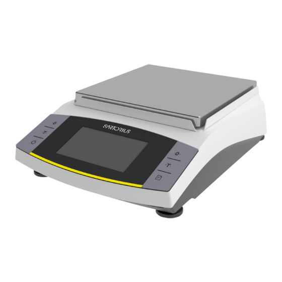
Entris
II Advanced Line
®
BCA Models | Modelle BCA | Modèles BCA | Modelo BCA | Modelli BCA | Modelos BCA
Precision Balances | Präzisionswaagen | Balances de précision | Balanzas de precisión
Bilance di precisione | Balanças de Precisão
1000068556
Advertisement


Need help?
Do you have a question about the Entris II Advanced Series and is the answer not in the manual?
Questions and answers