
Related Manuals for Sartorius WM Series


Summary of Contents for Sartorius WM Series
- Page 1 PRESENTED BY JPBOWLIN.COM 817.332.8116 J.P. Bowlin is a quality-driven Calibration Company that has provided calibration, repair and sales of all types of weighing and measurement products since 1931.
- Page 2 Operating Instructions Sartorius WM.. Models Weighing in Motion 98648-009-48...
-
Page 3: Table Of Contents
Contents 3 Preliminary Remarks 16 Troubleshooting The following symbols are used 16 Error Codes in these instructions: § indicates required steps 3 Intended Use 16 Weight Discrepancies 3 Warranty 16 Troubleshooting Electrical Problems $ indicates steps required only under 3 Safety Instructions 16 Errors in Normal Operation certain conditions 3 Safety Instructions regarding the... -
Page 4: Preliminary Remarks
Danger! regulations for accident prevention and feed and discharge. WM series equip- Denotes a dangerous situation. Fatal or environmental protection. National ment can be used to check samples at least serious injury, or considerable... -
Page 5: Safety Instructions For The User
– The following regulations and guidelines – Inform operating personnel before any Safety Instructions regarding must be observed during transport, installa- work is performed on the equipment, the Pneumatics tion and operation of the equipment: including maintenance and service work. –... -
Page 6: Observing Environmental Protection Regulations
– Dust cover for display and control unit CE Equipment Designation Label (Example) Sartorius Fast-Factory Special Version: 40004525 VF1812 Order no. Internal ID no. SARTORIUS AG GÖTTINGEN Germany WM35GEP – I000Q 91000001 230V ac 50/60 Hz 0.3K W Yr of mfr. 2000 Model Serial no. Power supply/frequency... -
Page 7: Installation Instructions
Installation Instructions Ambient Conditions Choose a suitable location for setting up the machine/system. The place of installation should be dry, level and even. The allowable operating tempera- ture range is -10°C to +40°C (14°F to 104°F). Observe the following when choosing a location for the equipment: –... -
Page 8: Adjusting The Checkweigher
Adjusting the Checkweigher Important Note: In addition to the usual tools, a 1-meter spirit level is required for adjusting the check- weigher. § Loosen the locknuts on the leveling feet (1). § Extend or retract the leveling feet until the level indicator on the weighing platform of the checkweigher indicates a level position. -
Page 9: Changing The Conveyor Direction
Changing the Conveyor Direction You can change the direction of conveyance by turning the entire checkweigher around (i.e., the checkweigher with frame; models WM35, 60 and 120). Only one direction of conveyance is possible for checkweigher model WM6. § Install the checkweigher without its support trestle to have it facing in the desired direc- tion. -
Page 10: Getting Started
Getting Started Connecting the Equipment to AC Power Danger! Before connecting the equipment to power, make sure the power cords are not live. The main switch must be in the “OFF” or “0” position. Installation For the electrical connection to the power supply, a feeder with a cross section of 3 + 1.5 mm is required. - Page 11 § Connect power supply cables in accordance with industry standards. Connect the black wire (L1; live) to terminal (1) Connect the blue wire (N; neutral) to terminal (2) Connect the green/yellow wire (PE; protective earth; grounding conductor) to the grounding terminal (screw) Refer to the wiring diagram for terminal assignments.
-
Page 12: Serial Data Interface
Serial Data Interface You can connect a Sartorius printer (see “Accessories”) or a computer to the serial ASCII RS-232 data interface on the control cabinet. § Plug the connector into the data interface. Note: Keep the threaded cap in a safe place. -
Page 13: Motor Cable
Motor Cable The motor cable is attached to the checkweigher frame at the factory. This must not be modified. § Check whether the motor cable is unobstructed and not in contact with any objects (e.g., the load plate on the checkweigher). §... -
Page 14: Inspection And Adjustment Following Initial Power-Up
Inspection and Adjustment following Initial Power-up The conveyor belt may have to be adjusted. It is important that this belt remain centered while the equipment is running. A conveyor belt tends to center itself at the point of highest tension. Due to the convexity of the drive roller, this point is the middle of the conveyor unit. - Page 15 Determining Weight Values (Inspection and Adjustment) You can check the accuracy of weighing either statically (with the equipment at a stand- still) or dynamically (with the conveyor belt running). In either case, the checkweigher must be zeroed and calibrated/adjusted by pressing the “Zero/tare” key (=) before you begin.
-
Page 16: Determining Weight Values
Determining Weight Values (The following description refers to the illustrations on the left.) The product approaches the measurement (weighing) section of the conveyor system. The product is detected on the conveyor belt. The weight value increases from “0” to “G” on the checkweigher display. The product now rests entirely on the conveyor belt. -
Page 17: Error Codes
If the error cannot be localized, or if the cause of the problem cannot be eliminated, please contact the Sartorius Technical Customer Service Center. Errors in Normal Operation There are a number of factors that can disrupt normal operation or cause errors. -
Page 18: Care And Maintenance
The LED on the photo sensor remains off: – the photo sensor is not adjusted correctly, thus transmitter and receiver are not communicating – transmitter or receiver is defective – the photo sensor has been wired incorrectly (e.g., during recent replacement) –... -
Page 19: Annual Maintenance
Important Note: The 4 screws for fastening the weighing platform to the frame must not be tightened nor loosened. Make sure that these screws cannot be adjusted or manipulated. Annual Maintenance We recommend having the equipment inspected annually by our customer service center. Electrical Maintenance Always perform the following inspections first: 1. -
Page 20: Rs-232 Ascii Interface
6. Turn on the motor; switch position “ON” – Does the display of the FC’s protective switch show the most recently set frequencies? – Does the motor start? Note: We recommend drawing up a checklist for your maintenance personnel so that these inspections can be checked off, and thus documented, as they are performed. -
Page 21: Instructions For Recycling The Packaging
Product at photo sensor (conveyor belt outlet): Product at outlet detected (photo sensor) Output of measured value to serial interface (RS-232, ASCII, 16 characters): 40 – 70 ms Setting the control outputs <, =, > 100 ms (< or = or > or no signal) Conveyor belt speed Setting in control cabinet The conveyor belt speed is set in the control cabinet, at the motor controls, by changing... -
Page 22: Specifications
Specifications Model Model DCP... Model ECP... Model EDP... Model FCP... Model FDP... Conveyor belt width 300+200 400+200 400+300 500+200 500+300 Weighing capacity 25g to 6kg 25g to 6kg 25g to 6kg 25g to 6kg 25g to 6kg Max. overload capacity Total weight Throughput in pc/min* <109... - Page 23 Model Model MHE... Model OHE... Model RHE... Model RKE... Conveyor belt width 1100+700 1300+700 1500+700 1500+900 Weighing capacity 25g to 120kg 25g to 120kg 25g to 120kg 25g to 120kg Max. overload capacity Total weight Throughput in pc/min.* <45 <38 <33 <33 Conveyor belt speed (max.)
-
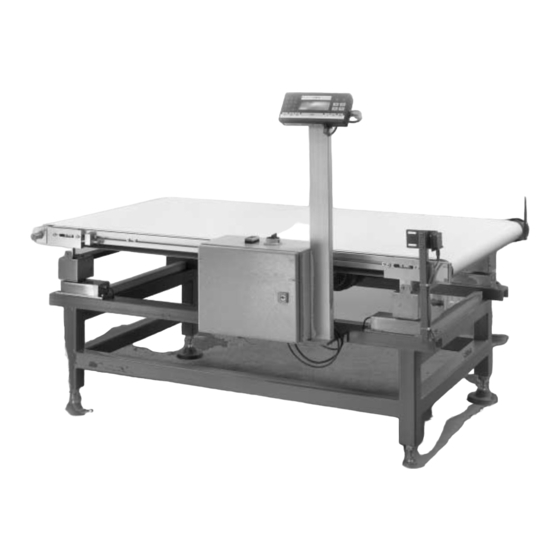
Page 24: General View Of The Equipment
General View of the Equipment WM35 WM60/120... -
Page 25: Dimensions (Scale Drawings)
Dimensions (Scale Drawings) All dimensions are given in millimeters Model: WM6DCP WM6ECP 400x200 300x200 Model: WM6EDP WM6FCP 400x300 500x200... - Page 26 Model: WM6FDP WM35GEP 600x400 500x300 Model: WM35IEP WM35LFP 1062 1000x500 800x400...
- Page 27 Model: WM60_120RKE WM60_120MHE 1510 1110 1180 1500x900 1100x700 Model: WM60_120RHE WM60_120WKE 1910 1510 1580 1180 1900x900 1500x700...
- Page 28 Model: WM60_120YKE WM60_120TKE 2110 1710 1780 1380 2100x900 1700x900 Model: WM60_120OHE 1310 1300x700...
-
Page 29: Circuit Diagrams
If a defect or failure occurs and can be eliminated only by replacing one or more parts of the system, the spare part(s) required must be obtained from Sartorius AG. The information (address, e-mail, fax and phone numbers) for contacting Sartorius is listed in the chapter entitled “Safety Instructions.”... - Page 30 Sartorius AG Weender Landstrasse 94–108 37075 Goettingen, Germany Phone +49.551.308.0 +49.551.308.3289 www.sartorius.com Copyright by Sartorius AG, Goettingen, Germany. All rights reserved. No part of this publication may be reprinted or translated in any form or by any means without the prior written permission of Sartorius AG.
Need help?
Do you have a question about the WM Series and is the answer not in the manual?
Questions and answers