Advertisement
Quick Links
PRIMA Pro
Operating Surgical Microscopy
User Manual
To ensure proper use of this instrument as well as to avoid injury while operating instrument, understanding this
manual Completely before use is highly recommended.
6182001-795
Prima Pro
Issue 1.0
Printed on Jan, 2024
Advertisement

Related Manuals for Labomed PRIMA Pro


Summary of Contents for Labomed PRIMA Pro
- Page 1 PRIMA Pro Operating Surgical Microscopy User Manual To ensure proper use of this instrument as well as to avoid injury while operating instrument, understanding this manual Completely before use is highly recommended. 6182001-795 Prima Pro Issue 1.0 Printed on Jan, 2024...
- Page 2 The information contained in this document was accurate at the time of publication. Specifications are subject to change without prior notice. LABOMED reserve the right to make changes to the product described in this user manual without notice and without incorporating those changes in any products already sold.
- Page 3 CHANGING THE OBJECTIVES AND EYEPIECES SYSTEM CONFIGURATION DIAGRAM THERMAL CUTT-OFF TENSION ADJUSTMENT MOVING POSITION OF THE SYSTEM CARE AND MAINTENANCE CLEANING AND DISINFECTION AMBIENT REQUIREMENT DISPOSAL TROUBLESHOOTING TABLE TECHNICAL SPECIFICATIONS GUIDANCE TABLES GLOSSARY WARRANTY 6182001-795 Prima Pro Issue 1.0 Printed on Jan, 2024...
- Page 4 1. INTRODUCTION AND INTENDED USE The LABOMED Prima is a surgical and diagnostic microscope which is adaptable for different surgical needs for consistent visualization during all intra operative phases of dental surgeries by providing magnified view of the surgical field without compromise to performance.
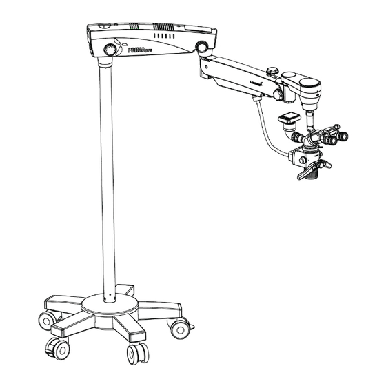
- Page 5 2. PRODUCT DESCRIPTION Catalogue No. 6183601 Model: Prima Pro Fig. 1 Castor Wheels With Brakes 15. Suspension Arm Spring Tension Adjustment Star Base Top 16. Suspension Arm Movement Locking Knob Star Base Bottom 17. Swivel Arm Star Base Leg 18. Wire Mesh with Fibre Light Guide Inside Column 19.
- Page 6 3. PRODUCT DESCRIPTION (CEILING MOUNT) Catalogue No. 6183603 Model: Prima Pro Fig. 2 1. Column 10. Eyepieces 2. Cover Mount (to be used in false ceiling only) 11. Both Hand Release Electromagnetic Clutch 3. Swivel Arm 12. Step Magnification Knob 4.
- Page 7 4. INSTALLATION REFERENCES (CEILING MOUNT) CEILING MOUNT (STANDARD ARM) Fig. 3 6182001-795 Prima Pro Issue 1.0 Printed on Jan, 2024...
- Page 8 INSTALLATION REFERENCES (CEILING MOUNT) continued CEILING MOUNT SYSTEM FOR 10 FEET CEILING HEIGHT Fig. 4 6182001-795 Prima Pro Issue 1.0 Printed on Jan, 2024...
- Page 9 INSTALLATION REFERENCES (CEILING MOUNT) continued MARKING REFERENCE Fig. 5 6182001-795 Prima Pro Issue 1.0 Printed on Jan, 2024...
- Page 10 INSTALLATION REFERENCES (CEILING MOUNT) continued Fig. 6 6182001-795 Prima Pro Issue 1.0 Printed on Jan, 2024...
- Page 11 6137200-804 ASSY. CEILING MOUNT PLATE 6137200-805 ASSY. CEILING COVER PRIMA SS-630 M4x10.0 SOCKET HD CAP SCREW SS-802 SOCKET FLAT HD SCREW M6x16 SS-854 RAWAL PLUG M10 SS-921 M12x40-SOCKET HEAD CAP SCREW 6182001-795 Prima Pro Issue 1.0 Printed on Jan, 2024...
- Page 12 Ensure that there is a 350mm diameter hole in the drop ceiling to mount the master Ceiling plate. Labomed Ceiling Mount system for wooden ceiling can be installed by fixing a flat wooden membrane at least 90mm thick to the joist and then mount the Master Ceiling Plate to the wooden membrane as shown in Fig.
- Page 13 Use Shims as required and adjust the RAWL Bolts/ Lag bolts until the column is Vertical. Tighten all screws securely. NOTICE: Shims and Shim materials are to be provided by the customer and are not furnished by Labomed. There are numerous shims and shim materials commercially available and no specific type or brand name is required.
- Page 14 Fully tighten all the bolts with 10mm allen key. All the procedure from Part 1 to 9 above is the responsibility of the customer to organise. Labomed representative will complete rest of the microscope Installation after this.
- Page 15 & regulations have been complied and the points listed below are taken care. The customer must keep this confirmation with his records. A copy of this document must be provided to labomed representative dealer. 3. The roof on which ceiling mount is to be mounted must have the following load capacity: Perpendicular force: minimum 1500 Nm.
- Page 16 List of Contents: Ceiling Kit Raval Plugs : 06 Nos Washers : 06 Nos Ceiling Mount : 01 Nos Column : 01 Nos Ceiling Mount Cover : 01 Nos 6182001-795 Prima Pro Issue 1.0 Printed on Jan, 2024...
- Page 17 6. PRODUCT DESCRIPTION (WALL MOUNT) Catalogue No. 6183602 Model: Prima Pro Fig. 11 1. Wall Mount Bracket 2. Mount Shaft 3. Swivel Arm 4. Suspension Arm 5. Suspension Arm Hydraulic Movement Lock Knob 6. Auto Balancing Arm Lock Knob 7. ABA (Auto Balancing Arm) Electromagnetic Clutch 8.
- Page 18 7. INSTALLATION REFERENCES (WALL MOUNT) Fig.12 6182001-795 Prima Pro Issue 1.0 Printed on Jan, 2024...
- Page 19 INSTALLATION REFERENCES (WALL MOUNT) continued Fig. 13 6182001-795 Prima Pro Issue 1.0 Printed on Jan, 2024...
- Page 20 INSTALLATION REFERENCES (WALL MOUNT) continued Prima Pro Wall Mount with Standard Suspension Arm Fig. 14 6182001-795 Prima Pro Issue 1.0 Printed on Jan, 2024...
- Page 21 Anchoring the Wall Mount Reference A. Paper Template for Marking B. Wall Mount Assembly C. Distance from Floor – Refer suitable height as per ordered configuration from Figure – 14. Fig. 15 6182001-795 Prima Pro Issue 1.0 Printed on Jan, 2024...
- Page 22 Anchoring the Wall Mount Reference A. Paper Template for Marking B. Wall Mount Assembly C. Distance from Floor – Refer suitable height as per ordered configuration from Figure –14. Fig. 15a 6182001-795 Prima Pro Issue 1.0 Printed on Jan, 2024...
- Page 23 INSTALLATION REFERENCES (WALL MOUNT) Wall Mount: Alternative Installation to the Patient’s Side (with Standard Suspension Arm) Fig. 16 6182001-795 Prima Pro Issue 1.0 Printed on Jan, 2024...
- Page 24 HORIZONTAL WALL MOUNT INSTALLATION REFERENCES (WOODEN WALL) Fig. 17 6182001-795 Prima Pro Issue 1.0 Printed on Jan, 2024...
- Page 25 HORIZONTAL WALL MOUNT INSTALLATION REFERENCES (SOLID BRICK WALL) VERTICAL WALL MOUNT INSTALLATION REFERENCES (SOLID BRICK WALL) Fig. 18 6182001-795 Prima Pro Issue 1.0 Printed on Jan, 2024...
- Page 26 Refer to Figure 15 & 15a. Measure the distance between the centres of the studs. The Labomed Wall Mount Model is designed to mount directly on a wall with wood studs spaced 406mm (16”) centre or on solid brick/concrete wall minimum 229mm (9”) thick wall.
- Page 27 Inch centre, it is recommended that 3/8" x 4" hex head lag screws are used. Fig. 20 WARNING: THE MOUNTING HARDWARE SUPPLIED FOR WOODEN WALL IS NOT DESIGNED FOR INSTALLATION TO WALL WITH STEEL STUDS OR TO CINDER BLOCK/MASONRY WALLS. 6182001-795 Prima Pro Issue 1.0 Printed on Jan, 2024...
- Page 28 7. Check the other side and insert shims as needed and then tighten the lag screws. 8. When the Wall Mount is level, both horizontally and vertically, securely tighten all Six lag screws. 6182001-795 Prima Pro Issue 1.0 Printed on Jan, 2024...
- Page 29 Ensuring the wall mount (top edge and front face) is level. NOTICE: Shims and shim materials are to be provided by the customer and are not furnished by Labomed. There are numerous shims materials commercially available and no specific type or brand name is implied.
- Page 30 WALL MOUNT INSTALLATION PROCEDURE (continued) Fig. 23 6182001-795 Prima Pro Issue 1.0 Printed on Jan, 2024...
- Page 31 2. Unscrew the threaded plug from wall mount shaft as shown in fig-23. 3. Assemble the Arm on wall mount shaft referring fig.22 and Re-install the threaded plug into place. 4. Complete the rest of Installation as per fig.1,2,3 or 4 as ordered. 6182001-795 Prima Pro Issue 1.0 Printed on Jan, 2024...
- Page 32 A copy of this document must be provided to labomed representative dealer. 3. The wall on which wall mount is to be mounted must have the following load capacity: Perpendicular force: minimum 1500 Nm Also take into account any additional loads acting on the wall.
- Page 33 Such activities as the installation of the flange and the installation of conduits and electrical lines are the customer’s responsibilities. List of Contents: Wall Mount Kit Raval Plugs : 06 Nos Washers : 06 Nos Wall Mount : 01 Nos 6182001-795 Prima Pro Issue 1.0 Printed on Jan, 2024...
- Page 34 WARNING: DO NOT REPAIR OR SERVICE THIS INSTRUMENT WITHOUT AUTHORIZATION FROM THE MANUFACTURER. ANY REPAIR OR SERVICE TO THIS INSTRUMENT MUST BE PERFORMED BY EXPERIENCED PERSONAL OR DEALERS WHO ARE TRAINED BY LABOMED OR SERIOUS INJURY TO THE OPERATOR OR PATIENT MAY OCCUR.
- Page 35 CAUTION: REMOVE THE AC POWER PLUG FROM THE WALL SOCKET WHILE CHECKING FOR A BLOWN FUSE. CAUTION: DO NOT ROLL THE MICROSCOPE OVER CABLES OR HOLES. CAUTION: DO NOT REMOVE FERRITE BEADS IF APPLIED TO CABLES. 6182001-795 Prima Pro Issue 1.0 Printed on Jan, 2024...
- Page 36 Permissible humidity range during transport and storage. Permissible pressure range during transport and storage. The product complies with US and Canadian safety requirements. Permissible temperature range during transport and storage. 6181001-795 6182001-795 Prima Pro Issue 1.0 Printed on Jan, 2024...
- Page 37 For Europe, per MDR 2017/745, the unit is a Class I instrument, per rule 13, Annex VIII. • For the United States, the FDA classification is Class I. • Please observe all applicable accident prevention regulations. 6182001-795 Prima Pro Issue 1.0 Printed on Jan, 2024...
- Page 38 5. Observation Head, (inclined or ergo) as ordered. 6. Pair of eyepieces, as ordered. 7. Power cord. 8. Installation Kit A. Allen wrench 5 mm B. Allen wrench 8 mm 9. User manual 6182001-795 Prima Pro Issue 1.0 Printed on Jan, 2024...
- Page 39 Fig. 27. Fig. 27 5. Take out the Star Base from the wooden box and place it on the floor shown in. Fig. 28 and Fig.29 . Fig. 28 Fig. 29 6182001-795 Prima Pro Issue 1.0 Printed on Jan, 2024...
- Page 40 Knob (I) as shown in Fig.- 32. c. Make sure the safety screw (1) is installed and tightened at position (2) so the coupling does not detach if knob (I) is accidentally unscrewed. Fig. 32 6182001-795 Prima Pro Issue 1.0 Printed on Jan, 2024...
- Page 41 Make sure the light guide has been routed through wire mesh into the carrier system such that the microscope is not obstructed and can be moved in its entire range of movement without stretching, kinking, or twisting the light guide. Fig. 34 6182001-795 Prima Pro Issue 1.0 Printed on Jan, 2024...
- Page 42 Two fuses are provided in this, i.e. one is live fuse and second as spare fuse. Replace the blown fuse with live fuse and secure back the fuse compartment. For fuse replacement refer label shown in fig.37. Fig. 37 6182001-795 Prima Pro Issue 1.0 Printed on Jan, 2024...
- Page 43 ELECTRICAL CONNECTIONS (continued) 3. DATA PLATE FOR PRIMA PRO MICROSCOPE 4. PRIMA WIRING CODING DIAGRAM 6182001-795 Prima Pro Issue 1.0 Printed on Jan, 2024...
- Page 44 This knob shown as A in Fig. 38 lock the UP/DOWN movement of the suspension arm at the desired height by turning it clockwise. 7. ADJUSTING TENSION ON ROTARY MOTION OF INCLINED CARRIER Refer Section 23 TENSION ADJUSTMENT for more details. 6182001-795 Prima Pro Issue 1.0 Printed on Jan, 2024...
- Page 45 Fig. 43 Single Chip White LED with over 2250 white lumen's. Lumen maintenance of greater than 70% after 60000 Hrs. Environment friendly ROHS Compliant. Typical spectrum is 400 - 700 nm. 6182001-795 Prima Pro Issue 1.0 Printed on Jan, 2024...
- Page 46 4. Make sure that the magnification changer is engaged in the index point at the click stop position. 5. Focusing for highest magnification, change all the magnification field of view must be in focus only fine focusing in required for sharp focus. 6182001-795 Prima Pro Issue 1.0 Printed on Jan, 2024...
- Page 47 It can be thread in by rotating in clockwise direction. 2. To install the eyepieces, insert in the eye tubes of observation head. 3. To install the eyepieces, insert in the eye tubes of observation head. Fig. 48 6182001-795 Prima Pro Issue 1.0 Printed on Jan, 2024...
- Page 48 ADAPTER FLOOR MOUNT ASSISTOSCOPE CMOS CAMERA TIL TABLE ERGO HEAD (0-210°) CCD ATTACHMENT CMO -200 CMO -250 CMO -300 CMO -400 CMO 200-270 CMO 300-400 CMO 200-400 MICROSCOPE BASE Fig. 49 6182001-795 Prima Pro Issue 1.0 Printed on Jan, 2024...
- Page 49 Use hexagonal wrench of 8mm in bolt (A) shown in fig.52 rotate it clockwise to increase desired tension on Gas spring. 4. Re-tighten the two screws. Fig. 52 5. Put back the plate. 6182001-795 Prima Pro Issue 1.0 Printed on Jan, 2024...
- Page 50 8. Do not go over steps and edges: the stand, might topple! 9. Be extremely careful when moving over slopes. 10. Do not park the stand on slopes 11. Press lock downwards. 12. Check whether the stand is locked in position. 6182001-795 Prima Pro Issue 1.0 Printed on Jan, 2024...
- Page 51 Part or circuit diagram etc. Surgical Microscope Maintenance/Servicing Check 6182001-795 Prima Pro Issue 1.0 Printed on Jan, 2024...
- Page 52 10. Do not clean products and optical components in a cleaning/disinfecting devices or ultra sound bath. 11. LABOMED MaxiLite coatings are fungal resistant. If you clean as described above, the coatings will not be damaged.
- Page 53 2. While cleaning, muslin cloth should not be dripped wet to prevent seepage and rusting to running/bare parts. 3. Alcohol is flammable, its use as a surface disinfectant should be in well-ventilated spaces only. 6182001-795 Prima Pro Issue 1.0 Printed on Jan, 2024...
- Page 54 The unit is marked with CE and is compliant to ANSI / AAMI EC 60601 - 1:2005. 28. DISPOSAL Disposal of the instrument must comply with locally applicable laws and regulations. 6182001-795 Prima Pro Issue 1.0 Printed on Jan, 2024...
- Page 55 Stand is unstable The brakes on the wheel are not Engage the brakes in use No image is visible in the field Magnichanger is not indexed Index magnichanger properly of view properly 6182001-795 Prima Pro Issue 1.0 Printed on Jan, 2024...
- Page 56 Microscope arm with magnichanger, head & 16.5 kg eyepieces H-base 58 kg Floor column 9 kg Ceiling mount column (for standard 3mtr 8 kg ceiling mount) Wall mount bracket 12 kg Ceiling mount bracket 9 kg 6182001-795 Prima Pro Issue 1.0 Printed on Jan, 2024...
- Page 57 The Prima is suitable for use in all establishment, other IEC 61000-3-2 than domestic, and those directly connected to the Flicker Complies public low voltage power network that supplies IED 61000-3-3 buildings used for domestic purposes. 6182001-795 Prima Pro Issue 1.0 Printed on Jan, 2024...
- Page 58 5 Seconds for 5 Seconds power supply or battery. Power Frequency 3A/m 3A/m Power frequency magnetic field should 50/60Hz Magnetic be that of a typical commercial or Field IEC 61000-4-8 hospital Environment. 6182001-795 Prima Pro Issue 1.0 Printed on Jan, 2024...
- Page 59 ME Equipment or ME System. *Over the frequency range 150kHz to 80 MHz, field strengths should be less than [V1] V/m. 6182001-795 Prima Pro Issue 1.0 Printed on Jan, 2024...
- Page 60 Note 1: At 80MHz and 800 MHz, the separation distance for the higher frequency range applies. Note 2: These guidelines may not apply in all situations. Electromagnetic propagation is affected by absorption and reflection from structures, objects and people. 6182001-795 Prima Pro Issue 1.0 Printed on Jan, 2024...
- Page 61 (Double Beam Splitter) splits light beam into two directions (one to eye and one to side port) for simultaneous user viewing and photography, videography, or co-observation. Ratio of light distribution is 70% for eyes and 30% to side ports for photography, videography and co-observation. 6182001-795 Prima Pro Issue 1.0 Printed on Jan, 2024...
- Page 62 LABOMED factory or authorized LABOMED Dealer. All claims under this warranty must be in writing and directed to the LABOMED factory or its authorized dealer for this device making the original sale and must be accompanied by a copy of the purchaser’s invoice.
- Page 63 By signing below, purchaser confirms that the correct and secure installation of mounting plates and hardware for the LABOMED Prima microscope(s) purchased is the sole responsibility of the purchaser and appointed contractor, and will comply with applicable building codes and good practices.
- Page 64 Revision History Rev.No. Date of Release DCR # Change App. By January, 2024 New Development New revision S.Bal 6182001-795 Prima Pro Issue 1.0 Printed on Jan, 2024...
- Page 65 6182001-795 Prima Pro Issue 1.0 Printed on Jan, 2024...
Need help?
Do you have a question about the PRIMA Pro and is the answer not in the manual?
Questions and answers