Table of Contents
Advertisement
Quick Links
Advertisement
Table of Contents

Related Manuals for Labomed Prima DNT


Summary of Contents for Labomed Prima DNT
- Page 1 PRIMA Operating Surgical Microscopy User Manual To ensure proper use of this instrument as well as to avoid injury while operating instrument, understanding this manual Completely before use is highly recommended. Prima 6137000-795 Issue 1.9 Printed on Sept,2021...
- Page 2 The information contained in this document was accurate at the time of publication. Specifications are subject to change without prior notice. LABOMED reserve the right to make changes to the product described in this user manual without notice and without incorporating those changes in any products already sold.
-
Page 3: Table Of Contents
Prima TABLE OF CONTENTS 1. INTRODUCTION AND INTENDED USE 2. PRODUCT DESCRIPTION 3.DIMENSIONS OF CEILING MOUNT 4. INSTALLATION REFERENCES (CEILING MOUNT) 6-11 5. CEILING MOUNT INSTALLATION 12-14 (A) DROP CEILING APPLICATIONS (B) LEVELING THE CEILING MOUNT SYSTEM (C) INSTALLING CEILING MOUNT ON CONCRETE CEILINGS 6.INSTALLATION REFERENCES (CONCRETE CEILING MOUNT) 15-16 7.DIMENSIONS OF WALL MOUNT ASSEMBLY... -
Page 4: Introduction And Intended Use
Prima INTRODUCTION AND INTENDED USE The LABOMED Prima is a surgical and diagnostic microscope which is adaptable for different surgical needs for consistent visualization during all intra operative phases of ENT & dentistry surgeries by providing magnified view of the surgical field without compromise to performance. -
Page 5: Product Description
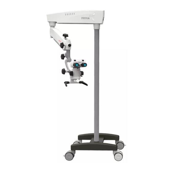
Prima PRODUCT DESCRIPTION Catalog no. 6138000-000 Model : Prima DNT Fig. 1 1. Wheel with Brakes 15. Magnification changer 2. H shape metal Base 16. Handle 3. Column 17. Common Main Objective 4. Swivel arm 18. Magnichanger locking knob 5. Suspension arm 19. - Page 6 Prima PRODUCT DESCRIPTION(continued) Catalog no. 6137000-000 Model : Prima ENT LABOMED Part # ....LABO AMERICA, I 9 N 2C 0 , . Auburn Court Fremont CA 94538 IP X6 www.laboamerica.com Fig. 1.1 1. Wheel with Brakes 15. Magnification changer 2.
-
Page 7: Dimensions Of Ceiling Mount
Prima 3.DIMENSIONS OF CEILING MOUNT CEILING MOUNT WITH STANDARD SUSPENSION ARM CONCRETE ROOF 91mm 525mm 600mm ±180° ±150° Fig. 2 Fig. 2 PRIMA CEILING MOUNT DESIGN FORMULA TO CALCULATE MICROSCOPE COLUMN LENGTH COLUMN LENGTH = (FLOOR TO CEILING HEIGHT - 1755mm) GIVEN EXAMPLE :- COLUMN LENGTH = 3660mm - 1755mm = 1905mm 6137000-795 Prima... - Page 8 Prima DIMENSIONS OF CEILING MOUNT(continued) CEILING MOUNT WITH LONG SUSPENSION ARM CONCRETE ROOF 91mm 525mm 922mm ±180° ±150° Fig. 3 6137000-795 Prima Issue 1.9 Printed on Sept,2021...
-
Page 9: Installation References (Ceiling Mount)
Prima 4. INSTALLATION REFERENCES (CEILING MOUNT) CEILING MOUNT: ALTERNATIVE INSTALLATION TO THE PATIENT’S SIDE WITH STANDARD ARM Fig. 4 6137000-795 Prima Issue 1.9 Printed on Sept,2021... - Page 10 Prima INSTALLATION REFERENCES (CEILING MOUNT)(continued) CEILING MOUNT: ALTERNATIVE INSTALLATION TO THE PATIENT’S SIDE WITH LONG ARM 986mm Fig. 5 6137000-795 Prima Issue 1.9 Printed on Sept,2021...
- Page 11 Prima INSTALLATION REFERENCES (CEILING MOUNT)(continued) WORK RANGE RECOMMENDED FOR IDEAL INSTALLATION SITE STANDARD ARM Fig. 6 6137000-795 Prima Issue 1.9 Printed on Sept,2021...
- Page 12 Prima INSTALLATION REFERENCES (CEILING MOUNT)(continued) WORK RANGE RECOMMENDED FOR IDEAL INSTALLATION SITE LONG ARM 986mm Fig. 7 6137000-795 Prima Issue 1.9 Printed on Sept,2021...
- Page 13 Prima INSTALLATION REFERENCES (CEILING MOUNT)(continued) MARKING REFERENCE 400mm 175mm 175mm Fig. 8 6137000-795 Prima Issue 1.9 Printed on Sept,2021...
- Page 14 Prima INSTALLATION REFERENCES (CEILING MOUNT)(continued) Fig. 9 6137000-795 Prima Issue 1.9 Printed on Sept,2021...
-
Page 15: Ceiling Mount Installation
1. Ensure that there is a 350mm diameter hole in the drop ceiling to mount the master Ceiling plate. Wooden membrane 2. Labomed Ceiling Mount system for wooden ceiling can be installed by fixing a flat wooden membrane at least 90mm thick to the joist Joist and then mount the Master Ceiling Plate to the wooden membrane as shown in Fig.10 . -
Page 16: (B) Leveling The Ceiling Mount System
3. Tighten all screws securely. NOTICE:Shims and Shim materials are to be provided by the customer and are not furnished by Labomed. There are numerous shims and shim materials commercially available and no specific type or brand name is required. -
Page 17: (C) Installing Ceiling Mount On Concrete Ceilings
Mount system” to correct any leveling concerns. 9. Fully tighten all the bolts with 10mm allen key. 10. All the procedure from Part 1 to 9 above is the responsibility of the customer to organise. Labomed representative will complete rest of the microscope Installation after this. -
Page 18: Installation References (Concrete Ceiling Mount)
Prima 6.INSTALLATION REFERENCES (CONCRETE CEILING MOUNT) RAVAL PLUG M10x75mm SS-854 (8-NOS.) TO BE FIXED IN CONCRETE CEILING BOLT M1Ox75mm SS-854 (8-NOS.) FIXED IN RAVAL PLUG SPRING LOCK WASHER 12MM SS-995 (6-NOS.) PILLAR M4x10 SOCKET HEAD CAP SCREW CEILING MOUNT PLATE SS-630 (2-NOS.) 6137200-805 (1-NOS.) M6x10 SOCKET SET SCREW... - Page 19 Prima INSTALLATION REFERENCES (CONCRETE CEILING MOUNT) CEILING CONNECTIONS CONNECTOR Fig. 14 6137000-795 Prima Prima Issue 1.9 Printed on Sept,2021...
-
Page 20: Dimensions Of Wall Mount Assembly
Prima 7.DIMENSIONS OF WALL MOUNT ASSEMBLY 406 ±0.2 Fig. 15 6-THRU HOLE Ø12.0 LIST OF CONTENTS 1. Paper template for marking - 1 2. Wall Mount Assembly -1 3. Hexagonal Lag bolts (for wooden walls) -6 4. Plain Washer -6 5. - Page 21 Prima DIMENSIONS OF WALL MOUNT ASSEMBLY(continued) WALL MOUNT WITH STANDARD SUSPENSION ARM 196mm 525mm 600mm THRU HOLE Ø12.0mm 406mm ±150° ±100° Fig .16 6137000-795 Prima Issue 1.9 Printed on Sept,2021...
- Page 22 Prima DIMENSIONS OF WALL MOUNT ASSEMBLY(continued) WALL MOUNT WITH LONG SUSPENSION ARM 525mm 922.6mm 196mm THRU HOLE Ø12.0mm 406mm ±100° ±150° Fig. 17 6137000-795 Prima Issue 1.9 Printed on Sept,2021...
-
Page 23: Installation Of Wall Mount
Prima 8.INSTALLATION OF WALL MOUNT WALL MOUNT WITH STANDARD SUSPENSION ARM & SWIVEL ARM WITH 8" EXTENSION ARM Fig.18 6137000-795 Prima Issue 1.9 Printed on Sept,2021... -
Page 24: Dimensions Of Wall Mount
Prima 9.DIMENSIONS OF WALL MOUNT Fig.19 6137000-795 Prima Issue 1.9 Printed on Sept,2021... -
Page 25: Installation References (Wall Mount)
Prima 10.INSTALLATION REFERENCES (WALL MOUNT) Wall mount: Alternative installation to the patient’s side (With standard suspension arm) 1021mm Fig. 20 6137000-795 Prima Issue 1.9 Printed on Sept,2021... - Page 26 Prima INSTALLATION REFERENCES (WALL MOUNT (continued) Wall mount: Alternative installation to the patient’s side (with long suspension arm) 1182mm Fig .21 6137000-795 Prima Issue 1.9 Printed on Sept,2021...
- Page 27 Prima INSTALLATION REFERENCES (WALL MOUNT (continued) Wall mount: MARKING REFERENCE Anchoring the Wall mount Reference A Paper Template for marking B Wall Mount Assembly C Distance from Floor- Refer suitable height as per ordered configuration from figure-1,2 or 4 6-COUNTER HOLE Ø16mm x 2.0mm DEEP THRU HOLE Ø11.0mm 406mm...
-
Page 28: Wall Mount Installation
Refer to Figure 21 and 22. Measure the distance between the centers of the studs. The Labomed Wall Mount Model is designed to mount directly on a wall with wood studs spaced 406mm (16”) centers or on solid brick/concrete wall minimum 229mm (9”) thick wall. - Page 29 Prima 11A.WALL MOUNT INSTALLATION FOR WOODEN WALL WALL MOUNT 6137100-806 6-NOS HEX HEAD WOODEN SCREW ? 10x100 6NOS-WASHER CAP RAWAL PLUG M10 PART NO SS-855(6-NOS) Fig .24 6137000-795 Prima Issue 1.9 Printed on Sept,2021...
- Page 30 Prima 11B.WALL MOUNT INSTALLATION FOR SOLID BRICK WALL WALL MOUNT 6137100-806 Fig.25 6137000-795 Prima Issue 1.9 Printed on Sept,2021...
-
Page 31: Wall Mount Installation Procedure
Prima 12.WALL MOUNT INSTALLATION PROCEDURE WALL MOUNT INSTALLATION ON STANDARD SIXTEEN INCH(16"406 MM) WOODEN WALL STUD SPACING For securing the Wall Mount System to construction using wooden wall studs spaced on 16 (406 mm) Inch centers, it is recommended that 3/8" x 4" hex head lag screws are used. Fig.26 WARNING: THE MOUNTING HARDWARE SUPPLIED FOR WOODEN WALL IS NOT DESIGNED FOR INSTALLATION TO WALL WITH STEEL STUDS OR TO CINDER BLOCK/MASONRY WALLS. - Page 32 Prima WALL MOUNT INSTALLATION PROCEDURE (continued) LEVELING THE WALL MOUNT PLATE ASSEMBLY It is important to ensure that wall mount (6137100-806) is level both horizontally and vertically, after installation. Leveling of the wall mount assembly is necessary to prevent the microscope system from drifting from side to side when it is being used at full extension.
- Page 33 Ensuring the wall mount (top edge and front face) is level. NOTICE: Shims and shim materials are to be provided by the customer and are not furnished by Labomed. There are numerous shims materials commercially available and no specific type or brand name is implied.
- Page 34 Prima WALL MOUNT INSTALLATION PROCEDURE (continued) Level Wall Mount Assembly Shim Fig.29 6137000-795 Prima Issue 1.9 Printed on Sept,2021...
- Page 35 Prima WALL MOUNT INSTALLATION PROCEDURE (continued) LEVELING THE WALL MOUNT ON MASONRY WALL 1. Slightly tighten the bolts on the top side- leaving the bottom bolts slightly loosened. 2. Place a level across the top of the back plate to check the horizontal leveling. See figure-13. 3.
- Page 36 A copy of this docu- ment must be provided to labomed representative dealer. 3. The wall Post on which the Prima wall mount is to be mounted must have the following load...
- Page 37 Prima WALL MOUNT INSTALLATION PROCEDURE (continued) Control and Power Supply of the system Note: The maximum weight of the surgical microscope including accessories must not exceed 7kg and the respective weight of our accessory equipment is specified in the price list. The weight of the mount including the surgical microscope is as follow: Ceiling mount kit: Approx..17 kg.
-
Page 38: Warning And Cautions
WARNING: THIS INSTRUMENT SHOULD BE USED IN STRICT ACCORDANCE WITH THE INSTRUCTIONS OUTLINES IN THIS USER’S GUIDE. THE SAFETY OF THE OPERATOR AND THE PERFORMANCE OF THE INSTRUMENT CANNOT BE GUARANTEED IF USED IN A MANNER NOT SPECIFIED BY LABOMED. WARNING: DO NOT REPAIR OR SERVICE THIS INSTRUMENT WITHOUT AUTHORIZATION FROM THE MANUFACTURER. - Page 39 Prima WARNING AND CAUTIONS(continued) WARNING: THIS INSTRUMENT IS NOT SUITABLE FOR USE IN THE PRESENCE OF FLAMMABLE ANESTHETIC MIXTURES, SUCH AS OXYGEN OR NITROUS OXIDE. WARNING: LED RADIATION - DO NOT STARE DIRECTLY INTO THE BEAM WHEN THE MICROSCOPE IS IN THE ON POSITION. WARNING: THE USE OF ACCESSORIES OR CABLES OTHER THAN THOSE SPECIFIED, WITH THE EXCEPTION OF THOSE SOLD BY THE MANUFACTURER AS REPLACEMENT PARTS FOR THE INTERNAL COMPONENTS, MAY RESULT IN INCREASED EMISSIONS OR DECREASED IMMUNITY OF THE...
-
Page 40: Explanation Of Symbols
Prima 14. EXPLANATION OF SYMBOLS Caution: Observe all warning labels and notes! If any label in missing on your instrument or has become illegible, please contact us or one of our Authorized representatives. We will supply the missing labels. Brightness Control: After the illumination has been switched on, the user can continuously adjust brightness by turning the knob appropriately. -
Page 41: Standards And Directives
Prima 15. STANDARDS AND DIRECTIVES The instrument described in this user manual has been designed in compliance with the following standards: • ISO 8600-3 First edition 1997-07-01 AMENDMENT 1 Optics and Optical instruments-Medical endo- scopes and endoscopic accessories Part 3: Determination of field of view and direction of view of endoscopes with optics. -
Page 42: Condition Of Instrument At Time Of Unpacking/Supply
Prima 16. CONDITION OF INSTRUMENT AT TIME OF UNPACKING/SUPPLY The appliance is delivered in sub-assembled modular groups along with one Installation Kit and one user manual. Please check for the following when unpacking the device: 1. Mobile supporting base with brakes on Castor wheels, or the type of mounting system. 2. -
Page 43: Installation Of Base (Mobile Stand)
Prima 17A. INSTALLATION OF BASE (MOBILE STAND) Open the center support assembly box as shown in fig.30. Fig.30 Remove the tool kit and foam sheets as shown in fig.31. Fig.31 3. Lift up the Centre Support assembly as shown in fig.32. Fig.32 Place the Centre Support assembly on the floor as shown in fig.33. - Page 44 Prima INSTALLATION Lift the wheel support assembly and cover as shown in fig.36. Place it (Wheels down) under one end of the center support as shown in Fig.37. Repeat procedure for the other wheel support assembly. Fig.36 8. Align the holes of the centre support with the holes of both wheel supports and tighten the screws as shown in Fig.37.
-
Page 45: Microscope Installation
Prima 17B. MICROSCOPE INSTALLATION 1 Open the Microscope Box. Remove pillar (Column) from the box. Engage this column onto the shaft matching the guide holes on column has shaft, as shown as B in Fig.40. 1a Align the tapped holes of the column with the shaft and tighten three allen screws from the sides, as shown as C in Fig.41. - Page 46 Prima INSTALLATION Retrieve the inclined coupling assembly from the packing and follow as below refer Fig.44. • Install the coupling to the suspension arm by sliding the guiding shaft (1) into the suspension arm. • Lock the inclined coupling with the threaded plug (3). Make sure that safety screw must tight in place at position (2) to avoid sudden falling of the coupling.
-
Page 47: Electrical Connections
Prima 18. ELECTRICAL CONNECTIONS Connect the power cable to the AC inlet socket (2) provided on the back of the swivel arm as shown in the fig.47. Switch on the power from on/off switch (2). Note: Power supply is designed with universal input 100V - 240V AC, 50/60HZ. - Page 48 Prima ELECTRICAL CONNECTIONS (continued) 4. PRIMA WIRING CODING DIAGRAM 6137000-795 Prima Issue 1.9 Printed on Sept,2021...
-
Page 49: Control Elements
Prima 19. CONTROL ELEMENTS 1 ON/OFF SWITCH It is located on the back of the swivel arm. At ‘ON’ position, green LED glows and cooling fan startsrunning. Keep the intensity control knob at Minimum level before switching on the system. To save burning life of LED, switch OFF the appliance if the microscope is not in use for longer time. - Page 50 Prima 6 FILTER CHANGE LEVER Refer Fig. 53(K). Filter change Lever is located in right side of the magnichanger housing. Use lever by pulling out to change the filter and push back to main light. 7 BRAKES Fig. 53 Locks the stand from unwanted movement by pressing down the two brakes provided on caster wheels.
-
Page 51: Instructions For Using The Microscope
Prima 20. INSTRUCTIONS FOR USING THE MICROSCOPE WARNING: INSTRUMENT IS UNSAFE FOR MRI ENVIRONMENT. SETTING UP OF MICROSCOPE: 1. Lock all the brakes on base wheels after setting up of microscope on the attendance area for stability. 2. Although tension on microscope is factory pre-set as per the ordered configuration. - Page 52 Prima MAIN MICROSCOPE The objective lenses with focal lengths of 250mm, 300mm and 400mm are available for different working distances. Also Variable working distance CMO like NuVar 7, NuVar 10 and NuVar 20 also available on demand. For more details NuVar refer brochure.
-
Page 53: Changing The Objectives & Eyepieces
Prima 21. CHANGING THE OBJECTIVES & EYEPIECES 1. The objectives can be taken out by rotating i in anti-clock wise direction. It can be thread in by rotating in clockwise direction. 2. To install the eyepieces, insert in the eye tubes of observation head. -
Page 54: Use Of Accessories
Prima 22. USE OF ACCESSORIES Part No.: 6138000-000 Model: Prima DNT VESA MOUNT 6137500-800 EYE PIECE 10X16 EYE PIECE 12.5X16 6120010 6135012 TILTABLE ERGO HEAD (0-210°) (6122015) 6134130-113 6134130-112 DOUBLE IRIS BAYONET BAYONET 6214051 6134130-111 6134130-110 MOUNT MOUNT ROTO PLATE... - Page 55 Prima USE OF ACCESSORIES(continued) Part No.: 6137000-000 Model: Prima ENT VESA MOUNT 6137500-800 EYE PIECE 10X16 EYE PIECE 12.5X16 6120010 6135012 STRAIGHT HEAD 6121025 6134130-113 6134130-112 BAYONET BAYONET 6134130-111 6134130-110 MOUNT MOUNT BAYONET BAYONET CANON SONY ROTO PLATE MOUNT MOUNT EOMS NEX-5N 6134115-801...
-
Page 56: Thermal Cut-Off
Prima 23. THERMAL CUT-OFF The instrument is designed with safety provisions. fans in the electrical box provide free - and forced - air circulation to cool the electronic components. The instruments also includes a built-in-safety mechanism called "auto thermal cut-off". This mechanism is activated through Thermistors when the LED temperature rises above 80 degree C. -
Page 57: Moving Position Of The System
Prima 25. MOVING POSITION OF THE SYSTEM Position of the system for safe transportation Fold the system as shown before moving RELOCATING THE STAND 1. Turn off the unit at the power switch. 2. Disconnect the power cable. 3. Remove the video cable from the video modules (e.g., video monitor, USB monitor) and the camera control unit. - Page 58 Prima 26. CARE AND MAINTENANCE This instrument is a high grade technological product and not required any special periodical Maintenance if handed carefully. To ensure optimum performance and safe working order of the Instrument, its safe functioning must be checked once every 12 months as per table below. We Recommended having this check performance by our service representative as part of regular Maintenance work.
-
Page 59: Care And Maintenance
Do not use ethanol and spirit. 10. Do not clean products and optical components in a cleaning/disinfecting devices or ultra sound bath. 11. LABOMED MaxiLite coatings are fungal resistant. If you clean as described above, the coatings will not be damaged. -
Page 60: Cleaning And Disinfection
Prima 27. CLEANING AND DISINFECTION Following disinfectants are recommended for cleaning and disinfection. 1. Normal household bleach (Sodium hypochlorite 5%)- strength 5000 ppm(10 parts water 1 part bleach). 2. 70% Isopropyl alcohol. Procedure: • Take a muslin cloth. • Moist it to feel wet •... -
Page 61: Ambient Requirement
Prima 28. AMBIENT REQUIREMENT +10˚C..+40˚C For Operation Temperature 30%..90% Rel. Humidity (without condensation) Air Pressure 700hPa..1,060hPa -40˚C..+70˚C Temperature For Transportation and Storage Rel. Humidity 10%..100% (without condensation) Air Pressure 500hPa..1,060hPa The unit meets the essential requirements stipulated in Annex I of the 93/42/EEC and Annex IX Rule 13 of MDR 2017/745 Governing medical devices. - Page 62 Prima 30. TROUBLESHOOTING TABLE Problem Possible Cause Remedy No illumination Plug in power cable Power cable not plugged in Press the power switch to ON Power switch in OFF position position Defective instrument fuse Change the fuse Change the power cable Defective power cable Contact in-house technician Line power failure...
-
Page 63: Troubleshooting Table
Prima ontinued) TROUBLESHOOTING TABLE(c Problem Possible Cause Remedy The brakes on the wheels are not Engage the brakes Stand is unstable in use Magnichanger is not indexed No image is visible in the Index magnichanger properly properly field of view 6137000-795 Prima Issue 1.9 Printed on Sept,2021... -
Page 64: Technical Specifications
Prima 31. TECHNICAL SPECIFICATIONS Binocular Tubes Ergo viewing tube 0° - 210° (tiltable), IPD 49-78mm Optional: Straight viewing tube 90°, IPD 45-78mm Eyepieces WF 10x/18mm with retractable eye guards,diopter adjustment ± 7mm and diopter lockOptional: WF 12.5x/18mm; fixed eye guards. Magnichanger 5 step: 0.4x, 0.6X, 1.0X, 1.6X &... -
Page 65: Guidance Tables
Prima 32. GUIDANCE TABLES Guidance and Manufacturer’s Deceleration Electromagnetic Emissions All Equipment and Systems Guidance and Manufacturer’s Declaration - Electromagnetic Emissions The Prima is intended for use in the electromagnetic environment specified below. The customer or user of the Prima should ensure that it is used in such an environment. Emissions Test Compliance Electromagnetic Environment Guidance... - Page 66 Prima GUIDANCE TABLES (continued) Guidance and Manufacturer’s Deceleration Electromagnetic Emissions All Equipment and Systems Guidance and Manufacturer’s Deceleration - Electromagnetic Emissions Prima is intended for use in the electromagnetic environment specified below. The customer or user of the Prima should ensure that it is used in such an environment. Electromagnetic Environment IEC 60601 Test Immunity Test...
- Page 67 Prima GUIDANCE TABLES (continued) Guidance and Manufacturer’s Deceleration Electromagnetic Immunity Equipment and Systems that are NOT Life-Supporting Guidance and manufacturer’s Deceleration – Electromagnetic Immunity The Prima is intended for use in the electromagnetic environment specified below. The customer or user of the Prima ENT/DNT should ensure that it is used in such an environment. Immunity Test IEC 60601 Test Level Compliance...
- Page 68 Prima GUIDANCE TABLES (continued) Recommended separation distance between Portable and Mobile RF Communications equipment and the Prima for ME equipment and ME systems that are not Life-supporting. Guidance and Manufacturer’s Deceleration - Electromagnetic Immunity Recommended separation distance for between Portable and Mobile RF Communications equipment and the Prima The Prima is intended for use in electromagnetic environments in which radiated RF disturbances are controlled.
-
Page 69: Measures And Weight
Prima 33. MEASURES AND WEIGHT Prima - Microscope with Mobile Stand Total Weight: Approx. 88 kgs. WALL MOUNT CEILING MOUNT 1124.6mm 525mm 1124.6mm 525mm FLOOR MOUNT 1464.6mm 843mm 525mm 536mm 6137000-795 Prima Issue 1.9 Printed on Sept,2021... -
Page 70: Glossary
Prima 34. GLOSSARY Compensation of short-or-far-sightedness. This can be done for each Ametropia Compensation eye using the two individual eyepieces (range: +5 to -5 diopters). Distance front lens to object level (250mm). Working Distance Refers to the color characteristic of a light source. Using color Color Temperature temperature, one can set the color of a light source to warm or cold light Relative to the color of natural light. -
Page 71: Warranty
LABOMED factory or authorized LABOMED Dealer. All claims under this warranty must be in writing and directed to the LABOMED factory or its authorized dealer for this device making the original sale and must be accompanied by a copy of the purchaser’s invoice. - Page 72 Prima Revision History Rev. No. Date of Release DCR # Change App. By March 22,2016 DCR/13/16 Wiring Coding S.Bal diagram added. July 05,2017 DCR/4A/17 Section 3.0 S.Bal Warning Updates revised UPS requirement Oct 30,2018 DCR/19A/18 Page 35 updated S.Bal weight Added section 7.6 Feb 26,2019 DCR/6A/19...
- Page 73 920 Auburn Court Fremont, CA 94538 U.S.A. Phone: 510-445-1257 Fax: 510-991-9862 Email: sales@laboamerica.com www.laboamerica.com EU REP. Labomed Europe Essebaan 50 NL-2908 LK Capelle a/d IJssel The Netherlands Tel: +31 (0)10 4584222 Fax: +31 (0)10 4508251 E-mail: info@labomedeurope.com A16372 ISO 13485...
Need help?
Do you have a question about the Prima DNT and is the answer not in the manual?
Questions and answers