
Subscribe to Our Youtube Channel
Related Manuals for L3Harris XL Series


Summary of Contents for L3Harris XL Series
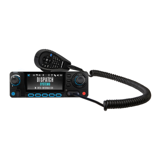
- Page 1 Operator’s Manual 14221-1850-2000 Rev. C, April 2024 XL Series Mobile Radios XL-200M and XL-185M...
- Page 2 Information and descriptions contained herein are the property of L3Harris Technologies. Such information and descriptions may not be copied or reproduced by any means or disseminated or distributed without the express prior written permission of L3Harris Technologies, PSPC Business, 221 Jefferson Ridge Parkway, Lynchburg, VA 24501.
-
Page 3: Table Of Contents
14221-1850-2000, Rev. C TABLE OF CONTENTS Section Page 1. REGULATORY AND SAFETY INFORMATION ..............8 SAFETY SYMBOL CONVENTIONS ................8 RF ENERGY EXPOSURE AWARENESS AND CONTROL INFORMATION FOR FCC OCCUPATIONAL USE REQUIREMENTS ............8 FEDERAL COMMUNICATIONS COMMISSION REGULATIONS ........ 9 COMPLIANCE WITH RF EXPOSURE STANDARDS .......... - Page 4 14221-1850-2000, Rev. C TABLE OF CONTENTS Section Page RADIO CONTROLS ....................27 BEFORE FIRST USE ....................30 POWER ON AND SET VOLUME ................30 VIDA ID ........................30 ® 4.4.1 User Login....................... 30 4.4.2 Provisioning ....................31 RADIO DISPLAYS ...................... 31 STATUS MESSAGES ....................
- Page 5 14221-1850-2000, Rev. C TABLE OF CONTENTS Section Page 4.29.2 Receiving an Emergency Call ................. 62 4.29.3 Stealth Emergency ..................62 4.30 MDC-1200 (ANALOG CONVENTIONAL ONLY) ............62 4.30.1 Normal PTT Operation ..................62 4.30.2 MDC PTT ID Receive Handling ..............63 4.30.3 Emergency Declaration ..................
- Page 6 5.22 EMERGENCY CHECK-IN TIMER ................95 5.23 WI-FI CLIENT SELECTION ..................96 5.24 EXTERNAL SPEAKER ....................96 6. PROGRAMMING ........................98 L3HARRIS DEVICE MANAGEMENT ................. 98 PROGRAMMING VIA RPM2 ..................98 WI-FI PROGRAMMING ....................99 EDIT CHANNEL (ANALOG AND P25 CONVENTIONAL ONLY) ........ 99 OTAP ........................
- Page 7 14221-1850-2000, Rev. C TABLE OF CONTENTS Section Page Figure 11-1: Options Network Configuration ................. 118 Figure 11-2: Wi-Fi Configuration ....................118 Figure 11-3: Service Name ....................... 118 Figure 11-4: Enable Wi-Fi in RPM2 ................... 119 Figure 11-5: Enable Wi-Fi Programming Mode on Radio ............120 LIST OF TABLES Table 1-1: Calculated Minimum Safe Distance from LMR Antenna (Based on Maximum Gain of Non-Yagi/Non-Log Periodic Antennas) ..............
-
Page 8: Regulatory And Safety Information
Failure to comply with these precautions or with specific warnings elsewhere violates safety standards of design, manufacture, and intended use of the product. L3Harris assumes no liability for the customer’s failure to comply with these standards. -
Page 9: Federal Communications Commission Regulations
FEDERAL COMMUNICATIONS COMMISSION REGULATIONS Before it was marketed in the United States, the XL Series mobile radio was tested to ensure compliance with FCC RF energy exposure limits for two-way mobile radios. When two-way radios are used as a consequence of employment, the FCC requires users to be fully aware of and able to control their exposure to meet occupational requirements. -
Page 10: Mobile Antennas
Based on the highest radiated RF power and the highest antenna gain in antennas to be used with the XL Series mobile radio, the distances listed are considered as safe distances for controlled and uncontrolled environments with the XL Series mobile radio transmitting at a maximum 50% duty cycle. -
Page 11: Approved Accessories
RF exposure guidelines and may violate FCC regulations. For a list of approved accessories, refer to the radio’s Installation Manual and/or the Products and Services Catalog. 1.4.3 Contact Information For additional information on RF exposure and other information, contact L3Harris using one of the contact links listed in Section 10. REGULATORY APPROVALS 1.5.1... -
Page 12: Fcc Part 15
14221-1850-2000, Rev. C 1.5.2 FCC Part 15 This device complies with Part 15 of the FCC Rules. Operation is subject to the following two conditions: 1. This device may not cause harmful interference, and 2. This device must accept any interference received, including interference that may cause undesired operation. -
Page 13: Common Hazards
14221-1850-2000, Rev. C COMMON HAZARDS The operator of any mobile radio should be aware of certain hazards common to the operation of vehicular radio transmissions. Possible hazards include but are not limited to the following: Explosive Atmospheres – Just as it is dangerous to fuel a vehicle while its engine is running, •... -
Page 14: Safe Driving Recommendations
14221-1850-2000, Rev. C SAFE DRIVING RECOMMENDATIONS The American Automobile Association (AAA) advocates the following key safe driving recommendations: • Read the literature on the safe operation of the radio. Keep both hands on the steering wheel and the microphone in its hanger whenever the vehicle is •... -
Page 15: Operating Tips
NB or WB channel. In this case, adjacent channel interference would increase and performance would degrade. There would also be some level of performance degradation if a NB transmission is received on a WB channel and vice-versa. L3Harris equipment meets the emission mask which minimizes any impact. -
Page 16: Renseignements Sur La Réglementation Et Sécurité
Le non-respect de ces précautions ou d’avertissements précisés ailleurs enfreint les normes de sécurité de la conception, de la fabrication et de l’utilisation prévue du produit. L3Harris n’assume aucune responsabilité pour le non-respect de ces normes par le client. -
Page 17: Règlements De La Federal Communications Commission (" Commission Fédérale Des Communications " Aux États-Unis)
14221-1850-2000, Rev. C Des changements ou modifications non expressément approuvés par L3Harris pourraient annuler le droit d’utilisation de l’équipement pour l’utilisateur. Cette radio bidirectionnelle utilise une énergie électromagnétique dans le spectre des radiofréquences (RF) pour permettre une communication à distance entre deux utilisateurs ou plus. -
Page 18: Conformité Aux Normes D'exposition Aux Rf
14221-1850-2000, Rev. C CONFORMITÉ AUX NORMES D’EXPOSITION AUX RF La radio mobile bidirectionnelle XL est conçue et testée pour être conforme à un certain nombre de normes et directives nationales et internationales quant à l’exposition humaine à l’énergie électromagnétique des RF. Cette radio est conforme aux limites d’exposition de l’IEEE et de la Commission internationale de protection contre les rayonnements non ionisants pour un environnement professionnel/contrôlé... -
Page 19: Antennes Mobiles
RF professionnelle ou contrôlée de la FCC. 2.3.3 Coordonnées Pour de plus amples renseignements sur l’exposition aux RF ou d’autres renseignements, contactez L3Harris en utilisant l’un des liens apparaissant à la Section 10. -
Page 20: Interférence Des Radiofréquences
14221-1850-2000, Rev. C INTERFÉRENCE DES RADIOFRÉQUENCES 2.4.1 Partie 15 de la FCC Cet appareil est conforme à la Partie 15 de la réglementation de la FCC. Le fonctionnement est soumis aux deux conditions suivantes : 1. Cet appareil ne doit pas causer une interférence nuisible; et 2. -
Page 21: Introduction
14221-1850-2000, Rev. C INTRODUCTION DESCRIPTION The XL Series Mobile Radio provides the advanced connectivity that first responders require while addressing evolving voice and data communications. It meets MIL-STD-810G for durability. XL Mobile Radios support P25 Trunking, P25 Conventional, EDACS ®... -
Page 22: Vehicle Communications Hub (Vch)
14221-1850-2000, Rev. C 3.1.1 Vehicle Communications Hub (VCH) The XL Vehicle Communications Hub (VCH) is the main LMR radio unit in a vehicular (mobile) radio system. A major feature of the VCH design is the use of IP networks for tethering multiple radio control heads. -
Page 23: Connected Core Module (Ccm)
14221-1850-2000, Rev. C 3.1.3 Connected Core Module (CCM) The Connected Core Module (CCM) is an optional module installed in the VCH of the XL Mobile. The CCM provides LTE, Wi-Fi, Bluetooth and GNSS capability to the VCH. The CCM can include various LTE Modules to meet regional LTE banding requirements. -
Page 24: Cleaning
Heavy-duty cleaning procedure as described in the maintenance manual. OPTIONS AND ACCESSORIES Only use L3Harris approved accessories. Refer to L3Harris’ Products and Services Catalog for the complete list of options and accessories available. Always use the correct options and accessories for the radio. - Page 25 14221-1850-2000, Rev. C DESCRIPTION PART # XL-200M OPTION # XL-185M OPTION # Antenna, Base, Magnetic Mount Low Loss AN-125001-008 XZ-AN6Y XT-AN6Y Mount, NMO Antenna, Magnetic, Heavy-Duty 12099-0370-01 XZ-AN7H XT-AN7H Antenna, Element, 700/800 MHz 3 dB AN-225001-001 XZ-AN8D XT-AN8D Antenna, Element, 900 MHz, 3 dB AN-225005-001 XT-AN8E Antenna, GPS, Roof Mount...
-
Page 26: Related Publications
14221-1850-2000, Rev. C RELATED PUBLICATIONS The following publications contain additional information about the radio and related products: MANUAL NUMBER DESCRIPTION 14221-1850-2010 XL Mobile Product Safety Manual 14221-1850-1000 XL Mobile Quick Guide 14221-1850-4000 XL Mobile Installation Manual 14221-1850-5000 XL Mobile Maintenance Manual 14221-1850-1010 Keypad Mobile Microphone (KMM) Quick Guide 14221-1850-2020... -
Page 27: Basic Operation
14221-1850-2000, Rev. C BASIC OPERATION RADIO CONTROLS Figure 4-1: Control Head Controls Figure 4-2: Keypad Mobile Microphone (KMM) Controls... -
Page 28: Figure 4-3: Xl Rugged Hand-Held Controller (Rhhc)
14221-1850-2000, Rev. C Figure 4-3: XL Rugged Hand-Held Controller (RHHC) Table 4-1 describes the default functions of buttons, knobs, and controls. Some can be programmed for different functions; see Section 6.6 for more information. NOTE For full descriptions of the XL RHHC controls, indicators, and connectors, refer to the XL RHHC Operator’s Manual, 14221-1850-2020. -
Page 29: Table 4-1: Radio Controls, Indicators, And Connectors
14221-1850-2000, Rev. C Bluetooth is not supported in a configuration that ONLY utilizes the XL RHHC (no control head). NOTE Table 4-1: Radio Controls, Indicators, and Connectors CONTROL/INDICATOR FUNCTION Turn knob clockwise to power on the radio and increase volume. Power On/Off Turn counterclockwise to decrease volume and put the radio into standby. -
Page 30: Before First Use
14221-1850-2000, Rev. C CONTROL/INDICATOR FUNCTION Indicates radio status: • Red = actively transmitting. Indicator LED Green = actively receiving. • Orange = actively transmitting encrypted. • If enabled via programming, LCD, LED, and keypad backlight brightness varies Ambient Light Sensor dynamically based on input from this sensor. -
Page 31: Provisioning
14221-1850-2000, Rev. C 4.4.2 Provisioning If provisioning is enabled via radio programming and the user has successfully logged in, the VIDA User Personality configured in the UAS is provisioned to the radio. When no VIDA Provisioned database is available, the radio will operate using the RPM2-programmed personality. -
Page 32: Status Messages
14221-1850-2000, Rev. C ICON DESCRIPTION ICON DESCRIPTION ICON DESCRIPTION (Orange) OTAR Disabled Alert(s) Present Transmitting Encrypted Talkaround Enabled OTAR Registered Vote Scanning Failsoft OTAR Registering Scanning Enabled Vehicular Repeater OTAR Rekeying Emergency Vehicular Repeater Transmit Power Level RX Mail Enabled High Wi-Fi Signal Transmit Power Level... -
Page 33: Predefined Menu Layouts
14221-1850-2000, Rev. C MESSAGE DESCRIPTION RX EMERGENCY An emergency call is being received. The radio displays the unit name or unit ID. P25 Trunked and EDACS – The radio has entered the Wide Area Scan mode to search for a new WIDE AREA SCAN system. - Page 34 14221-1850-2000, Rev. C CUSTOM MENU FULL RESTRICTED (DEFAULT SETTINGS) SCAN: ENABLE/DISABLE SCAN VIEW SCAN LIST EDIT ZONE SCAN LIST VIEW CUSTOM CHANNELS EDIT CUSTOM SCAN LIST CUSTOM SCAN SITE ROAM SITE ALIAS SECURITY: ENCRYPTION ENABLE ZEROIZE GLOBAL CKR ENABLE GCKR KEY SELECT ACTIVE KEY SET KEY LIST OTAR ENABLE...
- Page 35 14221-1850-2000, Rev. C CUSTOM MENU FULL RESTRICTED (DEFAULT SETTINGS) BLUETOOTH SETTINGS: BLUETOOTH ENABLE BLUETOOTH DISCOVERABLE VOLUME CONTROL BLUETOOTH SPEAKER EXTERNAL SPEAKER BLUETOOTH PAIRING BLUETOOTH PAIRING ADD BLUETOOTH PAIRING DELETE CLOCK SETTINGS: DISPLAY FORMAT TIME ZONE PROGRAM: ACTIVATE PLAN ACTIVATE PROFILE GPS SETTINGS: GPS ENABLE POSITION INFO...
-
Page 36: Menu
14221-1850-2000, Rev. C CUSTOM MENU FULL RESTRICTED (DEFAULT SETTINGS) Stealth Mode Settings LCD Enabled LED Enabled Backlight Enabled Side/Alert Tones Enabled Mobile Main Audio Path Enabled Voice Annunciation Enabled Channel/Group Knob Enabled ZONE CTZ EDIT MENU Press the Menu button while on the main display to access the menu. Depending on radio programming, this button accesses the top-level list of menus (Figure 4-5) or it accesses the Call Menu directly (Figure 4-6). -
Page 37: Table 4-5: Menu Navigation
14221-1850-2000, Rev. C Table 4-5: Menu Navigation MENUS DESCRIPTION CALL MENU: EXIT EMERGENCY MODE Exits emergency. See Section 4.29 for more information. TALKAROUND MODE Enable/disable talkaround. See Section 4.19 for more information. TONE ENCODE Analog conventional only – Transmits a programmed tone sequence on the current radio system and channel. - Page 38 14221-1850-2000, Rev. C MENUS DESCRIPTION UTILITY MENU: AUDIO SETTINGS: Allows the user to enable or disable the master volume control. When • MASTER enabled, it allows remote control heads to control the volume of the speaker attached to the back of the radio. When disabled, the volume knob on a remote-mount control head only controls the volume of the speaker attached to the control head.
- Page 39 Degrees (LAT LONG DD), Latitude/Longitude Degrees Minutes Seconds (LAT/LONG DMS), LAT/LONG DM, Military Grid Reference System (MGRS), or Universal Transverse Mercator (UTM). When enabled, the radio sends GPS data to a L3Harris-supplied PC client • SITUATION AWARENESS using Remote Network Driver Interface Specification (RNDIS) networking.
- Page 40 14221-1850-2000, Rev. C MENUS DESCRIPTION WIFI ACCESS POINT Power Wi-Fi On/Off. • POWER When the radio is configured as a Wi-Fi access point, displays the number of • CLIENT COUNT connected clients. Selecting CLIENT COUNT will display the MAC addresses of connected clients.
-
Page 41: Alert Tones
14221-1850-2000, Rev. C ALERT TONES The radio provides audible Alert Tones or “beeps” to indicate various operating conditions. Some of the most common tones are described in Table 4-6. Table 4-6: Alert Tones TONE DESCRIPTION SOUND/DURATION Ready to Talk Tone After a PTT is pressed, this is an audible indication (tone) for Unencrypted (Analog FM 1000 Hz tone for 25 ms... -
Page 42: Select Zone/System
14221-1850-2000, Rev. C 4.10 SELECT ZONE/SYSTEM A System is a group of channels or talkgroups that share a common set of parameters as programmed using RPM2. For example, a Trunking system defines the parameters needed to communicate on an infrastructure by agency or geographical region, such as WACN, System ID, Talkgroups, etc. -
Page 43: Select Group/Channel
14221-1850-2000, Rev. C 4.11 SELECT GROUP/CHANNEL The radio can be programmed with 1,250 talkgroups or 1000 channels per personality. Use the Group/Channel knob to select groups/channels. Numeric Channel Entry A button on the control head or KMM can be programmed for Numeric Channel Entry, which allows the user to manually enter the talkgroup/channel number from the keypad. -
Page 44: Group Calls
14221-1850-2000, Rev. C 4.13 GROUP CALLS 4.13.1 Transmit a Group Call A talkgroup is a group of radios with which you want to have private conversations. These groups can be divided into areas such as state, region, county, or large special events. Turn the Channel/Group knob to select the desired group (see Figure 4-1). -
Page 45: Individual Calls
14221-1850-2000, Rev. C If an in-band alias for the transmitting radio/console is sent to the received radios, the receive radios display that alias instead of the Unit ID or the I- CALL/Alias set contained in the receive radio’s personality, if any. The Alias alternates with the talkgroup name in the lower right display of the radio. -
Page 46: Receiving An Individual Call
14221-1850-2000, Rev. C Select KEYPAD to enter the Unit ID. Use the KMM or navigation keys and the Group/Channel Select Knob to enter the ID and press ENTER. The soft keypad is not displayed when a KMM is connected. NOTE 5. -
Page 47: User Profiles
14221-1850-2000, Rev. C 3. The radio rings and indicates a missed call if you do not respond. The ring sounds until you press PTT, view the missed call menu using the up navigation key, change channel/group/system, or power cycle the radio. 4. -
Page 48: Noise Cancellation
6.6. NOTE 4.16 NOISE CANCELLATION XL Mobile radios feature L3Harris’ proprietary noise suppression capability to provide clear and crisp voice quality in high-noise environments. This can be used in any mode, including analog and digital communications. The standard mic has two microphones; one located at the top (voice) and one on the bottom (noise reference) (see Figure 4-7 and Figure 4-8). -
Page 49: Enable Noise Cancellation
14221-1850-2000, Rev. C 4.16.1 Enable Noise Cancellation To enable Noise Cancellation: 1. Press the Menu button to access the menu. 2. Navigate to the UTILITY menu. 3. Scroll up or down to highlight AUDIO SETTINGS and press the Group/Channel Select Knob. 4. -
Page 50: Voice Versus Noise Reference Microphone
14221-1850-2000, Rev. C 4.16.4 Voice Versus Noise Reference Microphone The voice microphone is located on the top front face of the mic and the noise reference microphone is on the lower rear side. Do not obstruct either element during radio transmissions. Figure 4-7: Voice Microphone Figure 4-8: Noise Reference Microphone 4.17 ENABLE/DISABLE ENCRYPTION... -
Page 51: Channel Guard (Analog Conventional Only)
14221-1850-2000, Rev. C 4.18 CHANNEL GUARD (ANALOG CONVENTIONAL ONLY) Channel Guard is L3Harris’s trademark for CTCSS (tone squelch) and CDCSS (digital tone squelch). The Channel Guard menu is only accessible if the System is setup for CG SEL in the radio’s personality. -
Page 52: Use Talkaround To Bypass Repeater (Analog And P25 Conventional Only)
14221-1850-2000, Rev. C 4.19 USE TALKAROUND TO BYPASS REPEATER (ANALOG AND P25 CONVENTIONAL ONLY) You can bypass the repeater system to communicate directly with other radios on your current channel’s receive frequency. This is useful if you are out of range of a repeater or if a repeater is busy. -
Page 53: Type 99 Operation
14221-1850-2000, Rev. C A button on the control head or KMM can be programmed to toggle talkaround enable/disabled. See Section 6.6 for the various options that can be programmed to the control head buttons. If the talkaround Indication feature is enabled using RPM2, the radio plays a unique grant tone when a call is placed on a simplex channel or when talkaround has been enabled on a duplex channel. -
Page 54: Enable/Disable Type 99
14221-1850-2000, Rev. C 4.20.1 Enable/Disable Type 99 To enable Type 99: 1. Select T99 TOGGLE from the CALL menu. 2. Press the Group/Channel Knob to change T99 TOGGLE between ENABLED and DISABLED. T99 is displayed in the top of the radio display when Type 99 is enabled. A button or switch can be programmed to enable/disable Type 99 (see Section 6.6). -
Page 55: Receive Alert
14221-1850-2000, Rev. C 4. Highlight the desired unit in the list and press the Group/Channel Select Knob, or select KEYPAD to enter the Unit ID. 5. Press PTT to send the page. 4.21.2 Receive Alert 1. When receiving a Call Alert, the radio displays RX PAGE. 2. -
Page 56: Dtmf
14221-1850-2000, Rev. C 4. Select an entry from the list of pre-programmed entries or click DIRECT DIAL KEYPAD to enter the number directly. Direct Dial entries can have up to 31 characters (0-9, *, #, or a space; the space correlates to a pause.) Select OPTIONS to view details about the highlighted pre-programmed entry. - Page 57 14221-1850-2000, Rev. C 5. The scan icon is displayed on the main display when scanning is enabled. To start scan: 1. Press the Menu button. 2. Navigate to the SCAN menu. 3. Scroll up or down to highlight SCAN LISTS and press the Group/Channel Select Knob. 4.
-
Page 58: Stop Scan
14221-1850-2000, Rev. C 4.25 STOP SCAN 1. Press the Menu button. 2. Navigate to the SCAN menu. 3. Scroll up or down to highlight STOP SCAN and press the Group/Channel Select Knob. 4. Press the BACK soft key to exit the scan menu. 1. -
Page 59: Monitor And Squelch Types (Conventional Only)
14221-1850-2000, Rev. C 4.26 MONITOR AND SQUELCH TYPES (CONVENTIONAL ONLY) The monitor function allows you to temporarily turn off selected squelch to monitor for traffic that may not normally break squelch. The type of squelch used depends on an analog or digital channel. - Page 60 14221-1850-2000, Rev. C 4. Scroll up or down to highlight the desired scan list. Press the Group/Channel Select Knob. When scanning is started, indicates the active scan list; when scanning is stopped, indicates the active scan list. 5. Highlight the desired channel. 6.
-
Page 61: Failsoft
14221-1850-2000, Rev. C 4.28 FAILSOFT 4.28.1 Conventional Failsoft (EDACS) In the unlikely event of an EDACS system failure, communications can take place in Conventional Failsoft mode. The radio is automatically directed to a communications channel set up for this purpose. An increase in activity on the channel during Conventional Failsoft operation may be noticed, so be careful not to transmit until the channel is clear. -
Page 62: Receiving An Emergency Call
14221-1850-2000, Rev. C The radio goes through transmit and receive cycles if so configured. Speak into the microphone while the radio is transmitting or press PTT to talk. 3. To exit emergency, power cycle the radio or select EXIT EMERGENCY from the CALL menu. If enabled via programming, you can clear an emergency by pressing the button programmed for the Monitor/Clear function and then the emergency button. -
Page 63: Mdc Ptt Id Receive Handling
14221-1850-2000, Rev. C 4.30.2 MDC PTT ID Receive Handling When the radio receives an MDC PTT ID, it searches the MDC ID Alias List for an alias associated with the ID. If one is found, it displays the alias. If none is found, the radio displays the ID in hexadecimal. -
Page 64: Beon Operation
Radio (LMR) services onto the broadband capable third generation (3G) and 4G/LTE cellular networks. This includes the ability to provide highly integrated interoperability services between BeOn users on the cellular network and users of traditional LMR networks. L3Harris’ VIDA ®... -
Page 65: Advanced Operations
14221-1850-2000, Rev. C ADVANCED OPERATIONS VIEW/CHANGE PERSONALITIES Personalities contain radio programming information such as frequencies, channels, stations, and talk groups. Up to ten different personalities can be stored in the radio, but only one can be active at a time. 5.1.1 View Personalities 1. -
Page 66: Change Active Personality
14221-1850-2000, Rev. C 5.1.2 Change Active Personality To change the active personality: 1. Press the Menu button. 2. Navigate to the UTILITY menu. 3. Scroll up or down to highlight PROGRAM and press the Group/Channel Select Knob. 4. Scroll up or down to highlight the desired personality and press the Group/Channel Select Knob. -
Page 67: Situational Awareness (Sa) - P25 Conventional Only
14221-1850-2000, Rev. C 7. If personality is activated, the radio displays PLAN COMPLETE followed by the name of the personality. Press the OK soft key. You cannot activate a personality when the radio is transmitting an emergency. • A FAILED message may be displayed for errors such as invalid syntax in the fill or some •... -
Page 68: User Defined Zones
14221-1850-2000, Rev. C 6. Press the left or right navigation buttons to view the location of each unit. The color of each unit indicates its status as follows. Only one status can be shown at a time and are listed in priority order: •... - Page 69 14221-1850-2000, Rev. C 4. Press the OPTIONS soft key. 5. Press the up or down navigation buttons to select EDIT ZONE to create a zone or select RENAME ZONE to name the User Defined Zone (up to 16 characters are allowed). 6.
-
Page 70: Mixed System Zone
14221-1850-2000, Rev. C MIXED SYSTEM ZONE Mixed System Zones are defined using RPM2 and cannot be edited on the radio. If a Mixed System Zone is not configured using RPM2, it will not appear on the radio. Up to 250 Mixed System Zones can be defined. -
Page 71: Audio Settings
14221-1850-2000, Rev. C 5. After successfully entering the password, select and change the values of the displayed channel parameters. The password remains active until power cycle. Refer to Section 6.3 for more information. AUDIO SETTINGS From this menu, you can set audio settings such as speaker mute, noise cancellation, PTT, and tones. -
Page 72: Display Settings
14221-1850-2000, Rev. C DISPLAY SETTINGS To change display settings: 1. Press the Menu button. 2. Navigate to the UTILITY Menu. 3. Highlight DISPLAY SETTINGS and press the Group/Channel Select Knob. 4. Scroll through available display settings and press the Group/Channel Select Knob to change settings as desired: FRONT BACKLIGHT - Turn front display backlight On, Off, Momentary, or Momentary •... - Page 73 14221-1850-2000, Rev. C COLOR SCHEME - Change the color scheme of the top and front displays for optimum • viewing in day or night conditions. ACCENT BACKLIGHT - Turns the backlight for the control head or KMM buttons On, Off, •...
-
Page 74: Gps Settings
Decimal Degrees (LAT LONG DD), Latitude/Longitude Degrees Minutes Seconds (LAT/LONG DMS), LAT/LONG DM, Military Grid Reference System (MGRS), or Universal Transverse Mercator (UTM). SA OVER NETWORK - Allows the radio user to send GPS data to a L3Harris-supplied • PC client. -
Page 75: Position Info
14221-1850-2000, Rev. C POSITION INFO The Position Info screen displays the radio user’s location information. GPS must be enabled in the GPS Settings (see Section 5.8). To display position info: 1. Press the Menu button. 2. Navigate to the UTILITY menu. 3. -
Page 76: Pair Devices
14221-1850-2000, Rev. C 4. Highlight ENABLED and press the Group/Channel Select Knob to toggle YES/NO. A button on the control head or KMM can be programmed to enable/disable Bluetooth. 5.10.2 Pair Devices To pair devices: 5. Press the Menu button. 6. -
Page 77: Clock Settings
14221-1850-2000, Rev. C 13. Scroll up or down to highlight the desired device and press the PAIR softkey. 14. Pairing progress is displayed. For Bluetooth 2.0 devices, a pin code screen appears. • Enter the pin code and select OK. For Bluetooth 2.1 devices, a PASSKEY accept/deny screen appears. -
Page 78: Select Language
14221-1850-2000, Rev. C 5.12 SELECT LANGUAGE To change the language displayed by the radio: 1. Press the Menu button. 2. Navigate to the UTILITY menu. 3. Highlight CHANGE LANGUAGE and press the Group/Channel Select Knob. 4. Highlight the desired language and press the Group/Channel Select Knob. 5.13 SET UP SCAN The procedures in the following sections describe how to set up the scan list, home channels, and priority channels. -
Page 79: Trunked/Conventional Scanning
14221-1850-2000, Rev. C 5.13.1.3 Priority 2 Channel This channel will also be scanned more often than others. An example scan sequence would be P1, C2, P1, C3, P1, C4, P2, C5, P1, C6, P1, C7, P1, C8, P2, C9 etc. In addition, this channel will be scanned even while actively receiving on a non-priority channel. -
Page 80: Edit Scan List
14221-1850-2000, Rev. C 5.13.4 Edit Scan List Depending on the scan list options selected via RPM2, you may be able to add or remove channels/groups from the scan list. To edit the scan list: 1. Press the Menu button. 2. Navigate to the SCAN menu. 3. - Page 81 14221-1850-2000, Rev. C 3. Highlight SCAN LISTS and press the Group/Channel Select Knob. 4. Scroll up or down to highlight the desired scan list and press the Group/Channel Select Knob. 5. Press the up or down navigation buttons to highlight the desired channel/group. 6.
-
Page 82: Custom Scan Lists
14221-1850-2000, Rev. C 5.13.6 Custom Scan Lists The Mixed Zone Scan (MZS) feature gives the user the capability to scan based on a custom scan list that is assigned at the system level. The Custom Scan (CS) list can contain System and Channel/Group configurations across P25 Trunked, P25 Conventional, and Analog Systems. -
Page 83: Wide Area System Scan (P25 Trunked)
14221-1850-2000, Rev. C 5. Select ADD SCAN LIST. 6. Highlight the newly added scan list and press the VIEW/EDIT soft key and then select EDIT SCAN LIST. 7. Scroll left or right to display the desired system. 8. Scroll up or down to highlight the desired group/channel and the OPTIONS softkey. From the options menu, you can add/delete channels from the scan list and set/remove Priority 1 and Priority 2 channels. -
Page 84: Site Lock
14221-1850-2000, Rev. C 3. Scroll up or down to highlight SITE ROAMING and press the Group/Channel Select Knob to toggle Wide Area System Scan ENABLED/DISABLED. 4. Select BACK to exit the scan menu. 5.13.8 Site Lock The Site Lock feature provides a list of available, adjacent sites that the user can lock the radio to. -
Page 85: Radio Status
14221-1850-2000, Rev. C 5. From the OPTIONS menu, select LOCK SITE or SWITCH SITE. 5.14 RADIO STATUS The status feature allows the radio user to send a status condition to the site without making a voice call. There can be up to ten (10) status conditions programmed into the radio. For each status defined, there is an ID and an alphanumeric name. -
Page 86: Radio Message
14221-1850-2000, Rev. C 5.15 RADIO MESSAGE The message feature is used to send a message to the site without making a voice call. There can be up to ten (10) messages programmed into the radio. For each message defined, there is an ID and an alphanumeric name. -
Page 87: Radio Textlink Forms
14221-1850-2000, Rev. C 3. Highlight TEXTLINK MESSAGES and press the Group/Channel Select Knob. 4. Press the left or right navigation buttons to display the desired message. Press the Group/Channel Select Knob to send the message. Select CHG CALLEE to change the destination for the message. ... -
Page 88: View Received Messages
14221-1850-2000, Rev. C 5. Enter text into blank field(s) (up to eight alphanumeric characters) and press the NEXT soft key. 6. Select SEND to send the message. Select CHG CALLEE to change the destination for the message. Select TOD QUERY to get the time of day. 5.16.3 View Received Messages When the... -
Page 89: Faults/Alerts
• 5. If you view but do not delete the fault, the alert icon goes away on the main display. Contact L3Harris for assistance with diagnosing a fault. 5.18 TONE ENCODE Tone Encode is a generic tone encoding scheme for call identification when transmitting on a conventional system. -
Page 90: Encryption
14221-1850-2000, Rev. C 3. Scroll up or down to highlight TONE ENCODE and press the Group/Channel Select Knob. 4. Select the desired Tone Encode option from the list. 5.19 ENCRYPTION 5.19.1 Zeroize Keys from Radio It may be necessary to remove keys because of compromise or expiration. To zeroize keys from the radio: 1. -
Page 91: Global Encryption
14221-1850-2000, Rev. C 5.19.3 Global Encryption Global Encryption can be enabled when encryption keys are loaded on the radio and the selected Zone/System is encrypted. When Global Encryption is enabled on the radio, a Global Key is used for all encrypted transmissions until: Global Encryption is disabled. -
Page 92: Select Keyset
14221-1850-2000, Rev. C 6. Scroll up or down to highlight the desired global key and press the Group/Channel Select Knob. 7. RPM2 allows Key Numbers to be given Key Names. 8. The optional global key icon is displayed on the main display. 5.19.4 Select Keyset To select a keyset:... -
Page 93: Delete Individual Keys
14221-1850-2000, Rev. C 4. The available key lists are displayed. 5.19.6 Delete Individual Keys To delete individual keys from a keyset: 1. Press the Menu button. 2. Navigate to the SECURITY menu. 3. Scroll up or down to highlight KEY LIST and press the Group/Channel Select Knob. 4. -
Page 94: P25 Conventional Fallback
14221-1850-2000, Rev. C 3. Scroll up or down to highlight OTAR and press the Group/Channel Select Knob to toggle ENABLED/DISABLED. 4. Scroll up or down to highlight OTAR REKEY and press the Group/Channel Select Knob to request that the KMF update the keys in the radio. OTAR REKEY is only enabled if the radio has successfully registered for data operations. -
Page 95: Emergency Check-In Timer
14221-1850-2000, Rev. C 5.22 EMERGENCY CHECK-IN TIMER The Emergency Check In Timer is an added safety feature for a radio user who may be in a dangerous environment. If this timer expires before being cancelled by the radio operator, an emergency is declared. -
Page 96: Wi-Fi Client Selection
14221-1850-2000, Rev. C The following describes the External Output Alert Modes that can be enabled if one or more external outputs are configured for Emergency Check-In Timer: Warning On – Output is triggered when the timer counts down to the warning beep start •... - Page 97 14221-1850-2000, Rev. C When the External Speaker option is enabled in the personality, assigning the External Speaker function to a programmable button allows for additional control of output audio between speaker 1 and speaker 2. • When the programmable button configured for External Speaker is first pressed (active), the output volume of speaker 1 will stay fixed and speaker 2 will unmute at the current volume level (if previously activated, speaker 2 will unmute at its last registered volume level prior to going inactive).
-
Page 98: Programming
RPM2 installed. L3HARRIS DEVICE MANAGEMENT L3Harris Device Management is a web-based application that allows the user to collect basic status and version information, read and program personalities, and program firmware in XL radios over LTE or secure Wi-Fi. -
Page 99: Wi-Fi Programming
14221-1850-2000, Rev. C WI-FI PROGRAMMING The XL Mobile supports programming via Wi-Fi. Refer to Appendix A for information on configuring Wi-Fi. To enable Wi-Fi programming mode on the radio: 1. Press and hold the menu button while powering on the radio. 2. - Page 100 14221-1850-2000, Rev. C 5. Press the ENTER soft key. 6. Highlight and select the parameter to edit. For P25 channels, modify remaining channel settings: CHANNEL NAME - The Channel Name cannot be changed from this screen; RPM2 is • required to change the Channel Name. RX FREQUENCY - Receive frequency.
-
Page 101: Otap
14221-1850-2000, Rev. C RX CHAN GUARD is not available on this screen if it was enabled from the CALL menu as per Section 4.18. NOTE TX CHAN GUARD - Squelch type radio uses in transmit. Select None, CTCSS, or • CDCSS. -
Page 102: Programmable Buttons
14221-1850-2000, Rev. C PROGRAMMABLE BUTTONS When a KMM is used with the radio, the functions programmed to the one-dot, two-dot, and three-dot buttons are the same for the KMM and Control Head. NOTE Press the down navigation button while on the main display to view the functions assigned to the programmable buttons. - Page 103 14221-1850-2000, Rev. C FUNCTION DESCRIPTION Temporarily turn off selected squelch to monitor for traffic that may not normally break Monitor/Clear squelch. Also, press this button followed by the emergency button to clear an emergency. Noise Cancellation Turns Noise Cancellation On/Off. Enable/Disable Numeric Channel Entry Allows the radio user to manually enter the group/channel number (see Section 4.11).
-
Page 104: Programmable Icons
14221-1850-2000, Rev. C PROGRAMMABLE ICONS The display has space for up to 16 configurable icons, which can be programmed to display any of the following. Refer to Table 4-2. OTAR • • Blank PTT Disabled • • Alerts • Received Mail Bluetooth •... - Page 105 14221-1850-2000, Rev. C 2. To limit the impact of voice traffic on the network, set up a voice group set with a single voice group selected with transmit and receive disabled. a. Navigate to SETS P25 Group. Click Create Set. b.
- Page 106 14221-1850-2000, Rev. C 3. From the Personality Rail, navigate to SYSTEMS P25 Trunked and select the desired system. Under System Options Sets Options, select the group created in Step 2 from the Group Set drop-down. Leave the Phone Call Set and Individual Call Set fields blank. 4.
-
Page 107: Reference
14221-1850-2000, Rev. C REFERENCE MARINE FREQUENCIES Refer to Table 7-1: Marine Frequencies for a list of maritime frequencies per United States Coast Guard (USCG). A radio designated for shipboard use must comply with Federal Communications Commission Rule Part 80. Additional information about operating requirements in the Maritime Services can be obtained from the full text of FCC Rule Part 80 and from the US Coast Guard. -
Page 108: Narrowbanding
14221-1850-2000, Rev. C SHIP SHIP CHANNEL CHANNEL TRANSMIT RECEIVE NUMBER NUMBER 156.475 156.475 Non-Commercial. VDSMS 156.525 156.525 Digital Selective Calling (voice communications not allowed) 156.575 156.575 Non-Commercial. VDSMS 156.625 156.625 Non-Commercial (Intership only). VDSMS 156.675 156.675 Port Operations 156.725 156.725 Port Operations 156.875 156.875... -
Page 109: Lte Power On Timing
14221-1850-2000, Rev. C LTE POWER ON TIMING When switching firmware (from ATT to Verizon or back), it takes approximately five minutes. ® When powering on the CCM, there are two scenarios that can occur: • Band and power settings are correct. This is the normal scenario and takes approximately 60 to 70 seconds. -
Page 110: Glossary
14221-1850-2000, Rev. C GLOSSARY Advanced Encryption Standard AES-256 Advanced Encryption Standard, 256-bit AMBE+2 Advanced Multi-Band Excitation implementation 2 ANSI American National Standards Institute ASCII American Standard Code for Information Interchange Celsius Canada CDCSS Continuous Digital Coded Squelch System CH INFO Channel Information Common Key References Continuous Marine Broadcast... - Page 111 14221-1850-2000, Rev. C Key Encryption Key kilo (10 ) Hertz Key Identification Key Management Facility Keypad Mobile Microphone Key Management System Key Set Key Variable Loader (Motorola KVL Device) LAT/LONG DMS Latitude/Longitude Degrees Minutes Seconds LAT LONG DD Latitude/Longitude Decimal Degrees Light Emitting Diode Li-Ion Lithium-Ion...
- Page 112 14221-1850-2000, Rev. C Telecommunications Industry Association Transmit Ultra High Frequency UKEK Unique Key Encryption Key United States USCG United States Coast Guard Universal Time Coordinated Universal Transverse Mercator Volts, Direct Current Very High Frequency VIDA Voice Interoperability Data Access Vessel Traffic Service WEEE Waste from Electric and Electronic Equipment...
-
Page 113: Basic Troubleshooting
INSTALL FAILED Operations failed. Contact L3Harris if problem persists. Install Removal of existing SW Attempt install again and contact L3Harris INSTALL FAILED Operations failed. if problem persists. Mission Plan Mission plan activation failed. Use RPM2 to ensure plan validity. Contact In Progress L3Harris if failures persist. - Page 114 14221-1850-2000, Rev. C SCREEN/ DISPLAYED REASON RESOLUTION MENU ERROR MESSAGE Top-Level USER REGISTRATION The user has either entered Check the System ID and User ID. If they Screen FAILED FOR… the wrong values or the user correct, contact your network is not in the UAS database.
-
Page 115: Otar Errors/Information
IF RADIO INDICATES: 1. INVALID KEYSTORE ZEROIZE NEEDED - This occurs if the radio’s keys were loaded by the L3Harris Key Loader followed by an attempt to load UKEKs with the Key Loader or keys with the Motorola KVL. Fix by performing workaround 1, followed by 2. -
Page 116: Technical Assistance
11. WARRANTY Register this product within 10 days of purchase. Registration validates the warranty coverage and enables L3Harris to contact you in case of any safety notifications issued for this product. Register on-line at the Customer Care center webpage: https://www.l3harris.com/all-capabilities/pspc-customer-care... -
Page 117: Appendix Awi-Fi Programming
14221-1850-2000, Rev. C APPENDIX A WI-FI PROGRAMMING Due to numerous issues with discovering and programming radios connected to Enterprise Wireless networks, it is strongly suggested that a single Access Point Wireless network be used for programming radios with RPM2. See Section A.7 for more information. - Page 118 14221-1850-2000, Rev. C A.3 CONFIGURE THE PERSONALITY For a radio to be programmed over Wi-Fi, the active personality on the radio must be configured for connecting with the values that were set in Section A.2. The following steps detail how to configure an existing radio personality.
- Page 119 14221-1850-2000, Rev. C A.4 CONFIGURE THE RPM2 APPLICATION To ensure that RPM2 can discover radios over Wi-Fi, ensure that the Enable Wi-Fi checkbox is checked on the RPM2 Preferences screen as shown in Figure 11-4. This checkbox is unchecked by default. Figure 11-4: Enable Wi-Fi in RPM2 Also, as shown in Figure 11-4, the Service Name must be updated to reference the value in the active personalities for the radios you need to discover.
- Page 120 14221-1850-2000, Rev. C A.5 PUT THE RADIO IN WI-FI PROGRAMMING MODE When using multiple Control Heads, only power on the Control head that is being put into Wi-Fi mode. All other control Heads must remain powered off for the duration of Wi-Fi programming. Upon returning to operational mode and powering NOTE up the remaining control heads, they will be updated.
-
Page 121: Table 11-1: Wi-Fi Feature Support
14221-1850-2000, Rev. C Table 11-1: Wi-Fi Feature Support MULTIPLE RADIOS SINGLE RADIO (UP TO 16) Read Single Personality Read Multiple Personalities Write Single Personality Write Multiple Personalities Load Single Code File Load Multiple Code Files Voice Annunciation Feature Data Radio Name Install Splash Screen 6. - Page 122 14221-1850-2000, Rev. C If the radio was not discovered in RPM2 but an IP address is displayed on the radio screen as seen in Figure 11-5, this may mean that the Multicast (mDNS) messages are not making it through the Access Point. Consult the Access Point’s manual and make sure that those messages are not being filtered out.
-
Page 123: Appendix Bconfiguring Encryption
B.1 CREATE KEYS USING L3HARRIS KEY ADMIN L3Harris Key Admin is part of the L3Harris Key Manager and is used by the Crypto Officer (CO). The CO creates a Master Set of keys from which a Distribution Set is produced. Using the Key Admin software, the CO can save keys into Distribution key files for technicians to use in radios. - Page 124 14221-1850-2000, Rev. C 7. In RPM2, select P25 OPTIONS P25 OTAR/Keystores and set the following, referring to the RPM2 online help as necessary: a. Click Create to add a Keystore or edit the Default Keystore. b. Check Enable OTAR Options. c.
- Page 125 14221-1850-2000, Rev. C 8. Click Next to validate the password and continue. If the password is incorrect, the screen will display an error message. 9. Ensure USB is selected in the drop-down and click Next. 10. Select the radio from the drop-down and click Load. 11.
- Page 126 14221-1850-2000, Rev. C 8. Success and failure messages are shown on the KVL device’s screen. Additional keys can be loaded or read from the XL-Mobile while the screen shows KVL MODE ACTIVE – TRANSFER COMPLETE. 9. Once finished loading or reading keys from the XL-Mobile, press BACK or the blue HOME button to exit KVL Mode.
- Page 127 14221-1850-2000, Rev. C This page intentionally left blank.
- Page 128 About L3Harris Technologies L3Harris Technologies is an agile global aerospace and defense technology innovator, delivering end-to-end solutions that meet customers’ mission-critical needs. The company provides advanced defense and commercial technologies across air, land, sea, space, and cyber domains.
Need help?
Do you have a question about the XL Series and is the answer not in the manual?
Questions and answers