
Related Manuals for AEMC 607


Summary of Contents for AEMC 607
- Page 1 User Manual ENGLISH Clamp-On Meter Model 607 CLAMP-ON METERS WITH AEMC INSTRUMENTS ®...
- Page 2 Copyright Chauvin Arnoux , Inc. d.b.a. AEMC Instruments. All rights reserved. © ® ® No part of this documentation may be reproduced in any form or by any means (including electronic storage and retrieval or translation into any other language) without prior agreement and written consent from Chauvin Arnoux , Inc., as governed by United States and International copyright laws.
- Page 3 Statement of Compliance Chauvin Arnoux , Inc. d.b.a. AEMC Instruments ® ® certifies that this instrument has been calibrated using standards and instruments traceable to international standards. We guarantee that at the time of shipping your instrument has met the instrument’s published specifications.
-
Page 4: Table Of Contents
TABLE OF CONTENTS 1. INTRODUCTION ..............8 1.1 INTERNATIONAL ELECTRICAL SYMBOLS ......8 1.2 DEFINITION OF MEASUREMENT CATEGORIES (CAT) ..8 1.3 PRECAUTIONS FOR USE ............9 1.4 RECEIVING YOUR SHIPMENT ..........10 1.5 ORDERING INFORMATION ........... 10 1.5.1 Accessories ..............10 1.5.2 Replacement Parts ............ - Page 5 4. USE ..................25 4.1 INSTALLING THE BATTERIES ..........25 4.2 TURNING ON THE INSTRUMENT ........25 4.3 TURNING OFF THE INSTRUMENT ........26 4.4 CONFIGURATION ..............26 4.4.1 Auto Power Off ..............26 4.4.2 Current Threshold for True InRush Measurement ..
- Page 6 4.15 CONNECTING TO A COMPUTER........47 4.15.1 Bluetooth Connection ............47 4.15.2 Bluetooth Connection ............. 48 4.16 BLUETOOTH ON/OFF ............48 4.17 RECORDING DATA ..............49 4.17.1 Starting a Recording Session .......... 49 4.17.2 Stopping a Recording Session ........49 4.18 DOWNLOADING RECORDED DATA ........
- Page 7 5.2.15 Apparent AC Power Measurement ......... 59 5.2.16 Apparent AC+DC Power Measurement ......60 5.2.17 Measurement of Reactive AC Power ......60 5.2.18 Measurement of Reactive AC+DC Power....... 61 5.2.19 Calculation of the Power Factor (PF) ......61 5.2.20 Calculation of the Displacement Power Factor (DPF) ..62 5.2.21 Frequency Measurements ..........
-
Page 8: Introduction
Example: hardwired equipment in fixed installation and circuit breakers. CAT II: Corresponds to measurements performed on circuits directly connected to the electrical distribution system. Example: measurements on household appliances and portable tools. Clamp-On Meter Model 607 - User Manual... -
Page 9: Precautions For Use
■ As a safety measure, and to avoid repeated overloads on the inputs of the device, configuration operations should only be performed when the device is disconnected from all dangerous voltages. Clamp-On Meter Model 607- User Manual... -
Page 10: Receiving Your Shipment
1.5 ORDERING INFORMATION Clamp-On Meter Model 607 ............Cat. #2139.61 Includes set of 2 color-coded silicone insulated test leads, test probes and alligator clips, hard carrying case, (4) 1.5 V AA batteries, Bluetooth adapter,... -
Page 11: Product Features
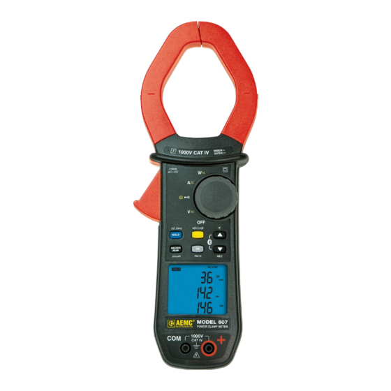
2. PRODUCT FEATURES The Clamp-On Meter Model 607 is a 10,000-count professional electrical measuring instrument that combines the following functions: ■ Current measurement ■ Inrush current / overcurrent (True InRush ) measurement ® ■ Voltage measurement ■ Frequency measurement ■ Harmonic distortion (THD) measurement ■... -
Page 12: Front Of Instrument
2.1 FRONT OF INSTRUMENT Figure 1 Item Designation See § Jaws with centering marks 4.5 to 4.13 (see connection principles) Physical Guard Rotary Function Switch Function Buttons Backlit Display Input Terminals Trigger Clamp-On Meter Model 607 - User Manual... -
Page 13: Rotary Switch
AC, DC, AC+DC voltage measurement (V) Continuity test Ω Resistance measurement AC, DC, AC+DC current measurement (A) Power measurements (W, var, VA) AC, DC, AC+DC 4.10 Power factor (PF), displacement power factor (DPF), and Energy Calculation Clamp-On Meter Model 607- User Manual... -
Page 14: Function Buttons
Enables/disables the energy metering mode Scrolls down the orders of harmonics or of pages of results in W, MAX/MIN/PEAK Enables/disables recording of current data in memory Enables/disables Bluetooth wireless transfer (in combination with 3) Clamp-On Meter Model 607 - User Manual... -
Page 15: Display
Symbol Description Alternating current or voltage Direct current or voltage AC+DC Alternating and Direct current Storage of the values and display HOLD RMS value Maximum DC or RMS value Minimum DC or RMS value Clamp-On Meter Model 607- User Manual... - Page 16 Total harmonic distortion with respect to the fundamental Total harmonic distortion with respect to the true RMS THDr value of the signal Recording in memory Bluetooth wireless communication Continuity test Auto Power Off disabled Low battery indicator Clamp-On Meter Model 607 - User Manual...
-
Page 17: Measurement Capacity Exceeded (Ol)
The OL (Over Load) symbol is displayed when the display capacity is exceeded. 2.5 TERMINALS The terminals are used as follows: Figure 5 Item Function COM (black) Input Terminal Jack + Positive (red) Input Terminal Jack Clamp-On Meter Model 607- User Manual... -
Page 18: Function Buttons
It can also be used to modify the default values in the configuration mode (see § 4.4). NOTE: is invalid in the MAX/MIN/PEAK and HOLD modes. Clamp-On Meter Model 607 - User Manual... -
Page 19: Button
NOTE: The backlight turns off automatically after 2 min. - Activates Bluetooth wireless communication - The symbol is the displayed combined with the NOTE: Activation of the Bluetooth mode button automatically stops the recording of the data. Clamp-On Meter Model 607- User Manual... -
Page 20: Button
AC. Peak+ is the maximum instantaneous peak and Peak- is the minimum instantaneous peak. NOTE: In this mode, the Auto Power Off function of the device is automatically disabled. The symbol is displayed on the screen. Clamp-On Meter Model 607 - User Manual... -
Page 21: Max/Min Mode + Activation Of The Hold Mode
AVG, PEAK- values detected before the button was pressed. short - When the button is pressed, the last value is held on the display. NOTE: The HOLD function does not interrupt the acquisition of new MAX/MIN/PEAK values. Clamp-On Meter Model 607- User Manual... -
Page 22: Access To True Inrush ® Mode ( Set Switch To )
This button is used to display the frequency measurements of a signal, of the power, and of the level and orders of harmonics. NOTE: This button is not functional in the DC mode. Clamp-On Meter Model 607 - User Manual... -
Page 23: Normal Mode
Function - First press: Displays the frequency of the harmonic order previously selected using the buttons, instead of order hxx short - Second press: Restores the display of order (hxx or hdC) Clamp-On Meter Model 607- User Manual... -
Page 24: Hz Function + Activation Of The Hold Mode
- Stores and displays the frequency with the RMS value and the DC component, then on a 2nd consecutive page, the crest factor short NOTE: The values displayed are those measured before the button is pressed. Clamp-On Meter Model 607 - User Manual... -
Page 25: Use
■ With the rotary switch set in the OFF position, turn the switch to the desired function. The display lights (all symbols) for a few seconds (see § 2.4), then the screen of the function chosen is displayed. ■ The clamp-on meter is now ready to make measurements. Clamp-On Meter Model 607- User Manual... -
Page 26: Turning Off The Instrument
The starting (Inrush) current measurement triggering threshold is fixed at 1 % of the least sensitive range. This value is 1 % of 99.99 A or 1 A. This threshold is not adjustable. Clamp-On Meter Model 607 - User Manual... -
Page 27: Recording Duration
The default parameters are then restored: ƒ Recording interval = 60 s Ω ƒ Continuity detection threshold = 40 ƒ True InRush triggering threshold = 10 % ® Clamp-On Meter Model 607- User Manual... -
Page 28: Voltage Measurement (V)
The symbol corresponding to the choice will then display. The measured value is displayed: In DC: Display Quantity 1st row Voltage V 2nd row DC RIPPLE in % 3rd row DC voltage component, V Clamp-On Meter Model 607 - User Manual... -
Page 29: Continuity Test
3. Connect the test probes or the alligator clips to the circuit or component to be measured. An audible signal is emitted if there is continuity and the measured value is displayed on the screen. Clamp-On Meter Model 607- User Manual... -
Page 30: Resistance Measurement Ω
(aligned with the centering marks). The device selects AC or DC automatically according to which measured value is larger. The AC or DC symbol displays blinking in auto detect mode. Clamp-On Meter Model 607 - User Manual... -
Page 31: Ac Measurement
Clamp the jaws around the conductor to be measured. The device selects AC or DC automatically. The measured values are displayed on the screen. Display Quantity 1st row RMS current A 2nd row Crest factor (CF) 3rd row current component A DC Clamp-On Meter Model 607- User Manual... -
Page 32: Dc Or Ac+Dc Measurement
1. The switch is set to . Select DC or AC+DC by pressing button until the desired choice is reached. 2. Clamp the jaws around the conductor to be measured. The measured values are displayed: Clamp-On Meter Model 607 - User Manual... - Page 33 DC RIPPLE in % 3rd row DC current component A In AC and AC+DC: Display Quantity 1st row Total RMS current A or T 2nd row Crest factor (CF) 3rd row DC current component, A Clamp-On Meter Model 607- User Manual...
-
Page 34: Current Or Overcurrent (True Inrush ® )
(starting of installation). For an established current (overload in an installation) see § 4.4.2. Display Quantity 1st row Inrh 2nd row True InRush value in A ® 3rd row Triggering threshold in A Clamp-On Meter Model 607 - User Manual... -
Page 35: Power Measurement W, Va, Var And Pf
2. The device automatically displays AC+DC. To select AC, DC, or AC+DC, press the button until the desired choice is reached. 3. Connect the black lead to the COM terminal and the red lead to terminal. Clamp-On Meter Model 607- User Manual... - Page 36 The measurement is displayed on screen. Display Quantity 1st row Active power W (DC, AC or AC+DC) 2nd row Reactive power var (AC or AC+DC) 3rd row Apparent power VA (AC or AC+DC) Clamp-On Meter Model 607 - User Manual...
-
Page 37: Balanced 3-Phase Power Measurement
L2 phase NOTE: The arrow on the jaws of the clamp (see the diagram below) must point in the presumed direction of flow of the current from the source (producer) to the load (consumer). Clamp-On Meter Model 607- User Manual... -
Page 38: Four Quadrant Diagram
■ negative active power = power generated ■ reactive power (var) and active power of the same sign = inductive power ■ reactive power and active power of opposite signs = capacitive power Clamp-On Meter Model 607 - User Manual... -
Page 39: Energy Metering Measurement
The metering sequence is as follows: The status of each meter is: - On <=> metering in operation - Off <=> metering stopped (values of the meters 0) - Stop <=> metering stopped (values of the meters preserved) Clamp-On Meter Model 607- User Manual... - Page 40 NOTE: Beyond 999 h 59 m 59 s ---h--m--s is displayed, but the internal metering duration keeps running correctly. View of the set of screens concerning Energy measurement by short presses on buttons: Clamp-On Meter Model 607 - User Manual...
- Page 41 The sequence of use is as follows: I - Supp h W ---> Supp L h VAR ---> Supp C h VAR ---> Supp h VA ---> I I <------------------------------------------------------------------------------------------- | Clamp-On Meter Model 607- User Manual...
-
Page 42: Frequency Measurement (Hz)
1. Set the switch to and press the displayed. 2. Select AC by pressing the button until the desired choice is reached. 3. Connect the black lead to the COM terminal and the red lead to terminal. Clamp-On Meter Model 607 - User Manual... -
Page 43: Frequency Measurement (A)
2. Select AC or AC+DC by pressing the button until the desired choice is reached. 3. Clamp the jaws around the conductor to be measured. The measured value is displayed on the screen. Clamp-On Meter Model 607- User Manual... -
Page 44: Total Harmonic Distortion (Thd) Measurement And Harmonics Order Display
2. Connect the black lead to the COM terminal and the red lead to terminal. 3. Place the test probes or the alligator clips on the terminals of the circuit to be measured. The measured value is displayed on the screen Clamp-On Meter Model 607 - User Manual... -
Page 45: Thd (A) Measurement
The THDf, THDr and A RMS symbols are displayed. NOTE: F irst press the button to place the meter in AC current measurement mode. 2. Apply the clamp to only the conductor concerned. The measured value is displayed on the screen Clamp-On Meter Model 607- User Manual... -
Page 46: Individual Harmonics And Frequency Of The Fundamental From Dc To The 25Th
The REC symbol is displayed. Recording of the measurement starts. The data recorded is in the format: MAX value – AVG Value – MIN Value – Unit – Mode (AC or AC+DC). Clamp-On Meter Model 607 - User Manual... -
Page 47: Connecting To A Computer
80 h 4.15 CONNECTING TO A COMPUTER 4.15.1 Bluetooth Connection The Model 607 is equipped with Bluetooth connectivity for downloading, displaying and deleting recorded data in the instrument’s memory. The instrument is supplied with a Bluetooth USB adapter for use with computers without Bluetooth capability. -
Page 48: Bluetooth Connection
Bluetooth can only be turned on or off when the instrument is not recording. To enable the Bluetooth press the buttons simultaneously. The symbol should appear in the upper right corner of the display. To disable Bluetooth press the buttons simultaneously; the symbol will turn OFF. Clamp-On Meter Model 607 - User Manual... -
Page 49: Recording Data
Control Panel. (NOTE: this is different from the PowerPad III Control Panel.) 2. Select View Recorded Data from the Instrument menu. 3. In the Recorded Data in Instrument window, select the Select All button and click on Delete All to erase the memory. Clamp-On Meter Model 607- User Manual... -
Page 50: Data Storage
The Model 607 captures Trend measurements at a user specified interval. 4.20.1 Trend Measurements The Model 607 stores the measurement of each of the inputs. In addition, the user can define the storage rate and type of measurement. 4.20.2 Recording with Memory Cleared... -
Page 51: Opening The Dataview ® Control Panel
Click the option Help Topics. This opens the PowerPad Control Panel Help system. Find and follow the instructions for connecting the instrument to the computer. For instructions about using DataView with the instrument, consult the ® PowerPad Control Panel Help system. Clamp-On Meter Model 607- User Manual... -
Page 52: Specifications
Input Impedance 10 M (1) Above 1000 V, a repetitive beep indicates that the voltage being measured is greater than the safety voltage for which the device is guaranteed. The display indicates OL. Clamp-On Meter Model 607 - User Manual... -
Page 53: Ac Voltage Measurement
Bandwidth in AC = 3 kHz. (2) Any value between zero and the min threshold of the measurement range (0.15 V) is forced to show on the display. Clamp-On Meter Model 607- User Manual... -
Page 54: Dc Current Measurement
Bandwidth in AC = 1 kHz (2) In AC, any value between zero and the min threshold of the measurement range (0.15 A) is forced to show on the display. Residual current at zero < 150 mA. Clamp-On Meter Model 607 - User Manual... -
Page 55: Ac+Dc Current Measurement
(from 10 Hz to 1 kHz in AC): ■ Accuracy: add ± (1.5 % R +0.5 A) to the values in the table above. ■ PEAK capture time: 1 ms min to 1.5 ms max. Clamp-On Meter Model 607- User Manual... -
Page 56: Crest Factor (Cf) Calculation
OL, or forced to zero, the RIPPLE displayed is an indeterminate value, 5.2.10 Continuity Measurement Ω Measurement Range (0.0 to 999.9) Open-circuit Voltage ≤ 3.6 V Measurement Current 550 µA Accuracy ± (1 % R +5 cts) Ω Buzzer Triggering Threshold Clamp-On Meter Model 607 - User Manual... -
Page 57: Resistance Measurement
(3) The measurement result may be affected by an instability linked to the current measurement (approximately 0.1 A). Example: For a power measurement made at 10 A, the instability of the measurement will be 0.1 A/10 A or 1 %. Clamp-On Meter Model 607- User Manual... -
Page 58: Active Ac Power Measurements
Quadrant 1: Active power P sign + (power consumed) Quadrant 2: Active power P sign - (power generated) Quadrant 3: Active power P sign - (power generated) Quadrant 4: Active power P sign + (power consumed) Clamp-On Meter Model 607 - User Manual... -
Page 59: Active Ac+Dc Power Measurements
(1) Display of OL above 2000 kVA in single-phase (1000 V x 2000 A). Bandwidth in AC in voltage = 3 kHz, in current = 1 kHz (2), (3) and (4) of previous § apply. Clamp-On Meter Model 607- User Manual... -
Page 60: Apparent Ac+Dc Power Measurement
- Signs of reactive powers according to the four-quadrant rule (§ 5.2.12): Quadrant 1: Reactive power Q sign + Quadrant 2: Reactive power Q sign + Quadrant 3: Reactive power Q sign - Quadrant 4: Reactive power Q sign – Clamp-On Meter Model 607 - User Manual... -
Page 61: Measurement Of Reactive Ac+Dc Power
Add +1 % for 10 % < THD < 20 % Add +3 % for 20 % < THD < 30 % Add +5 % for 30 % < THD < 40 % NOTE: The PF is always positive. Clamp-On Meter Model 607- User Manual... -
Page 62: Calculation Of The Displacement Power Factor (Dpf)
If the level of the signal is too low (< 10 % of the range, or V < 8 V or I < 9 A) or if the frequency is less than 5 Hz, the device cannot determine the frequency and displays displays Clamp-On Meter Model 607 - User Manual... -
Page 63: Specifications In Thdr
Specific characteristics in MAX/MIN mode in THD (from 10 Hz to 1 kHz): ■ Accuracy: add 1 % R to the values in the table above. ■ Capture time of the extreme: approximately 100 ms Clamp-On Meter Model 607- User Manual... -
Page 64: Harmonic Measurement Specifications
(-40 to +158) °F Temperature (-20 to +55) °C (-40 to +70) °C ≤ 90 % up to ≤ 90 % up to Relative Humidity (RH) 131 °F (55 °C) 158 °F (70 °C) Clamp-On Meter Model 607 - User Manual... -
Page 65: Mechanical Specifications
IEC-61010-2-30, and IEC-61010-2-32:1000 V CAT IV. Compliant with standard EN-61326-1 Electromagnetic compatibility Classification: residential environment Mechanical Strength Free fall: 2 m (in accordance with standard IEC-68-2-32) Housing: IP54 (per standard IEC-60529) Level of protection of the housing Jaws: IP40 Clamp-On Meter Model 607- User Manual... -
Page 66: Environmental Variations
3 % R + 1 ct 0.5 and I ≥ 10 A and capacitive) 8 % R + 1 ct 0.2 and I ≥ 20 A *Note in Temperature: Influence specified until 1000 A Clamp-On Meter Model 607 - User Manual... -
Page 67: Maintenance
(see § 3.1). 4. Remove the used batteries and replace them with (4) 1.5 V AA batteries, observing the polarities. 5. Close the battery compartment cover and screw it onto the housing. Clamp-On Meter Model 607- User Manual... -
Page 68: Repair And Calibration
Chauvin Arnoux , Inc. d.b.a. AEMC Instruments ® ® Phone: (800) 343-1391 (Ext. 351) Fax: (603) 742-2346 E-mail: techsupport@aemc.com www.aemc.com Clamp-On Meter Model 607 - User Manual... -
Page 69: Limited Warranty
Instruments, not by the distributor from whom it was purchased. ® This warranty is void if the unit has been tampered with, abused, or if the defect is related to service not performed by AEMC Instruments. ® Full warranty coverage and product registration is available on our website at www.aemc.com/warranty.html. - Page 70 NOTES:...
- Page 71 NOTES:...
- Page 72 99-MAN 100371 v13 AEMC Instruments ® 15 Faraday Drive • Dover, NH 03820 USA Phone: +1 (603) 749-6434 • +1 (800) 343-1391 • Fax: +1 (603) 742-2346 www.aemc.com © 2012 Chauvin Arnoux , Inc. d.b.a. AEMC Instruments. All Rights Reserved. ® ®...
Need help?
Do you have a question about the 607 and is the answer not in the manual?
Questions and answers