
Related Manuals for AEMC 6526


Summary of Contents for AEMC 6526
- Page 1 Megohmmeter Models 6526, 6532 and 6534 User Manual ENGLISH 1.800.561.8187 information@itm.com www. .com...
- Page 2 Chauvin Arnoux , Inc, AEMC , and DataView are registered trademarks of AEMC Instruments. ® ® ®...
- Page 3 Thank you for purchasing the Megohmmeter Model 6526, 6532, or 6534. For best results from your instrument: ■ Read these operating instructions carefully ■ Comply with the precautions for use WARNING, risk of DANGER! The operator must refer to these instructions whenever this danger symbol appears WARNING, risk of electric shock.
- Page 4 PRECAUTIONS FOR USE This instrument is compliant with safety standard IEC 61010-2-030, and the leads are compliant with IEC 61010-031, for voltages up to 600V in CAT IV or 1000V in CAT III. Failure to observe the following safety instructions may result in electric shock, fire, explosion, and damage to the instrument and installation.
-
Page 5: Table Of Contents
2.3.3 Continuity Measurement ..........................21 2.3.3.1 Lead Compensation ...........................22 2.3.3.2 Continuity Measuring .........................23 2.3.4 Resistance Measurement ..........................24 2.3.5 Capacitance Measurement (Models 6526 and 6532) ................24 2.4 Recording Data ..............................25 2.4.1 Recording a Measurement .........................25 2.4.2 Viewing Stored Recordings ........................26 2.4.3 Deleting Recordings ...........................27 2.4.3.1 Deleting a Single Recording.......................27... - Page 6 3.2.1 Voltage Measurement ..........................28 3.2.2 Frequency Measurement ...........................28 3.2.3 Insulation Measurement ..........................29 3.2.4 Continuity Measurement ..........................31 3.2.5 Resistance Measurement ..........................31 3.2.6 Capacitance Measurement (Models 6526 and 6532) ................31 3.2.7 Timer ................................32 3.2.8 Storage Memory ............................32 3.2.9 Bluetooth ..............................32 3.3 Operating Environment ............................32 3.3.1 Voltage Measurement ..........................32...
-
Page 7: Introduction
If the equipment appears to be damaged, file a claim immediately with the carrier and notify your distributor at once, providing a detailed description. Save the damaged packing container to substantiate your claim. Ordering Information: Megohmmeter Model 6526..........................Cat. #2155.53 Megohmmeter Model 6532..........................Cat. #2155.54 Megohmmeter Model 6534..........................Cat. #2155.55... -
Page 8: Accessories
Probe - Set of 2, Color-coded (Red/Black) Grip Probes ................... Cat. #2152.26 1.4 Description The Megohmmeters Models 6526, 6532, and 6534 are portable measuring instruments with digital displays. They are powered by batteries. These instruments can check the safety of electrical installations. For example, they can be used to test new installations before they are powered up, check an existing installation in a power-off condition, or troubleshoot an installation. -
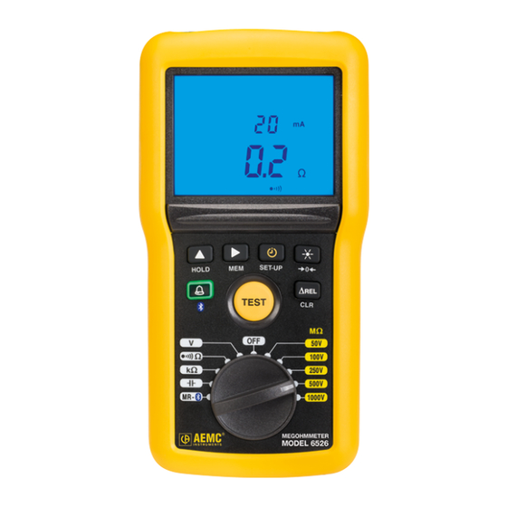
Page 9: Model 6526 (Front)
1.4.1 Model 6526 (Front) DARPI T1T2 G VHz % M mAµA M mAµA < > < ALARM ALARM G nF µF HOLD HOLD TEST Ω 250V Ω Ω 500V 100V Ω 250V 1000V 500V 1000V MR - MEGOHMMETER MODEL 6526 Figure 1 1. -
Page 10: Model 6532 (Front)
2. Blue backlit LCD 3. Six function buttons (see § 1.7) 4. TEST button to start insulation measurements (see § 2.2.2.1) 5. Eight-position rotary switch to choose the function or to turn the instrument OFF Megohmmeter Model 6526/6532/6534 1.800.561.8187 information@itm.com www. -
Page 11: Model 6534 (Front)
2. Blue backlit LCD 3. Six function buttons (see § 1.7) 4. TEST button to start insulation measurements (see § 2.2.2.1) 5. Ten-position rotary switch to choose the function or to turn the instrument OFF Megohmmeter Model 6526/6532/6534 1.800.561.8187 information@itm.com www. -
Page 12: Back Of Instrument
1.5 Back of Instrument Figure 4 1. Captive quarter-turn screw 2. Battery compartment cover 3. Mounting magnets, moulded into instrument case 4. Non-skid pads 5. Stand Megohmmeter Model 6526/6532/6534 1.800.561.8187 information@itm.com www. .com... -
Page 13: Terminals
Program the alarm thresholds (§ 2.1.3). Displays the difference between the present measurement and a stored reference measurement (§ 2.1.4). ∆Rel Records measurements (§ 2.3). Erase recorded measurements (§ 2.3.3). Enable Bluetooth wireless communication (§ 2.1.2). Megohmmeter Model 6526/6532/6534 1.800.561.8187 information@itm.com www. .com... -
Page 14: Lcd Display
When the measured value is below the minimum, the instrument displays - - - - . When measuring voltage, if the reading falls outside the range defined by the positive and negative limits, the instrument displays OL or – OL. Megohmmeter Model 6526/6532/6534 1.800.561.8187 information@itm.com www. -
Page 15: Operation
Note that this setting reverts to OFF when you turn OFF the instrument. press Displays the instrument model number. on press Displays the instrument firmware version. on press Displays the instrument hardware version. on press Return to the first press. on Megohmmeter Model 6526/6532/6534 1.800.561.8187 information@itm.com www. .com... -
Page 16: Bluetooth
(except during insulation measurements). For each testing mode, there are three pre-defined threshold values: ■ Continuity: < 2Ω, <1Ω and <0.5Ω ■ Resistance: >50kΩ, >100kΩ and >200kΩ Megohmmeter Model 6526/6532/6534 1.800.561.8187 information@itm.com www. .com... -
Page 17: Viewing Alarms
To activate this function, take a measurement, and then press the ∆REL button. This measurement becomes the reference (Rref) and will be stored and subtracted from subsequent measurement values (Rmeas). The ∆REL symbol appears on the LCD while this function is activated. Megohmmeter Model 6526/6532/6534 1.800.561.8187 information@itm.com www. -
Page 18: Hold Function
Pressing the HOLD button freezes the display of the measurement. This can be done in all functions except , DAR, PI). the MΩ settings, or during a timed measurement ( To unfreeze the display, press the HOLD button again. Megohmmeter Model 6526/6532/6534 1.800.561.8187 information@itm.com www. .com... -
Page 19: Backlighting
1. Set the switch to V or to one of the MΩ positions. Ω Ω 100V Ω 250V 500V 1000V MR - 2. Using the leads, connect the system to be tested to the instrument’s terminals. Megohmmeter Model 6526/6532/6534 1.800.561.8187 information@itm.com www. .com... - Page 20 The instrument displays the voltage on the terminals. It detects whether the voltage is AC or DC; and (for Models 6526 and 6532) if it is AC, displays its frequency. In the MΩ settings, th ymbol indicates that the voltage is too high (>25V) and that insulation measurements are prohibited.y.
-
Page 21: Insulation Measurement
25V in the system under test, pressing the TEST button has no effect because the test will be prohibited. 5. The resistance measurement is displayed on the LCD’s main display area and on the bar graph. The secondary display area indicates the test voltage generated by the instrument. Megohmmeter Model 6526/6532/6534 1.800.561.8187 information@itm.com www. -
Page 22: Test Button Operation
This enables the DAR function. This is used to calculate the dielectric absorption ratio DARPI T1T2 (the ratio of the measurement at 1 minute to the measurement at 30 seconds). press Exits timed test mode. Megohmmeter Model 6526/6532/6534 1.800.561.8187 information@itm.com www. .com... - Page 23 Poor or even dangerous 1.25 ≤ DAR < 1.6 2 ≤ PI < 4 Good 1.6 ≤ DAR 4 ≤ PI Excellent Press the TEST button to return to voltage measurement. TEST Megohmmeter Model 6526/6532/6534 1.800.561.8187 information@itm.com www. .com...
-
Page 24: Remote Control Probe (Optional)
If an external voltage >15V is detected in the system under test during the continuity measurement, the instrument is protected without a fuse. The continuity measurement is stopped and the instrument reports an error until the voltage disappears. Megohmmeter Model 6526/6532/6534 1.800.561.8187 information@itm.com www. -
Page 25: Lead Compensation
To remove the compensation of the leads, leave the leads open and press the button for >2 seconds. The LCD dis- plays the resistance of the leads and the symbol goes off. Megohmmeter Model 6526/6532/6534 1.800.561.8187 information@itm.com www. .com... -
Page 26: Continuity Measuring
3. Use the leads to connect the instrument to the system to be tested. The system to be tested must be powered down. The instrument displays the resistance and the current used in the test. Megohmmeter Model 6526/6532/6534 1.800.561.8187 information@itm.com www. -
Page 27: Resistance Measurement
2. Connect the system to be tested to the instrument. The device to be tested must be powered down and discharged. 3. The instrument displays the results. 2.3.5 Capacitance Measurement (Models 6526 and 6532) 1. Set the rotary switch to Ω... -
Page 28: Recording Data
The saved recording includes all information associated with the measurement, including voltage, current, > 2s duration of tests, T1 and T2 (for PI and DAR), and other data. The recording also includes a bar graph indi- cating how much available memory remains in the instrument. Megohmmeter Model 6526/6532/6534 1.800.561.8187 information@itm.com www. -
Page 29: Viewing Stored Recordings
5. Once you select the recording number, you can see all information associated with the measurement. Press the MEM button for >2 seconds, then use the button to scroll the information. 6. When finished viewing recordings, press MEM for >2 seconds. Megohmmeter Model 6526/6532/6534 1.800.561.8187 information@itm.com www. .com... -
Page 30: Deleting Recordings
4. To cancel, press the CLR button for >2 seconds. Otherwise, press the MEM button for >2 seconds to confirm the deletion. 5. The instrument displays a message indicating the memory is empty. Megohmmeter Model 6526/6532/6534 1.800.561.8187 information@itm.com www. -
Page 31: Technical Specifications
Frequency ranges DC and 15.3 at 800Hz 3.2.2 Frequency Measurement Measurement Range 15.3 to 399.9V 400 to 700V Resolution 0.1Hz Accuracy ± (1% R + 2 ct) ± (1.5% R + 1 ct) Megohmmeter Model 6526/6532/6534 1.800.561.8187 information@itm.com www. .com... -
Page 32: Insulation Measurement
= 250V: ± (3% R + 2 ct + 0.4%/GΩ) = 500V: ± (3% R + 2 ct + 0.2%/GΩ) For all test voltages, when the insulation resistance is ≤ 2GΩ the intrinsic uncertainty is ± (3% R + 2 ct). Megohmmeter Model 6526/6532/6534 1.800.561.8187 information@itm.com www. - Page 33 ± (10% R + 3 ct) Typical test voltage vs load curve The voltage as a function of the measured resistance is illustrated below: The range of operation per IEC 61557 is from 100kΩ to 2GΩ (see § 3.4). Megohmmeter Model 6526/6532/6534 1.800.561.8187 information@itm.com www.
-
Page 34: Continuity Measurement
400 to 1000kΩ Resolution 1Ω 10Ω 100Ω 1kΩ Accuracy ± (3% + 2 ct) Open voltage approximately 4.5V 3.2.6 Capacitance Measurement (Models 6526 and 6532) Capacitance Measurement Range 0.1 to 399.9nF 400 to 3999nF 4.00 to 10.0µF Resolution 0.1nF 10nF Accuracy ±... -
Page 35: Timer
Frequency 15.3 to 800Hz 2% R + 1 ct Supply voltage 6.6 to 9.6V V, F 0.1% R + 2 ct Common mode rejection 0 to 600V 50dB 40dB in AC 50/60 Hz Megohmmeter Model 6526/6532/6534 1.800.561.8187 information@itm.com www. .com... -
Page 36: Insulation Measurement
50V range, ≤5GΩ 0 to 1µF 250V range, ≤15GΩ 6% R + 2 ct 10% R + 2 ct 1000V range, ≤100GΩ Common mode rejection in AC 0 to 600Vac 50dB 40dB 50/60 Hz Megohmmeter Model 6526/6532/6534 1.800.561.8187 information@itm.com www. .com... -
Page 37: Resistance And Continuity Measurement
Accepts no perturbations Common mode at 200mA rejection in AC 0 to 600Vac at 20mA 50dB 40dB 50/60 Hz 3.3.4 Capacitance Measurement (Models 6526 and 6532) Influence Influencing Range of Influence Quantity Influenced Parameter Typical Maximum -20 to + 55°C Temperature µF... -
Page 38: Intrinsic Uncertainty And Operating Uncertainty
Dimensions (L x W x H): 211 x 108 x 60mm (8.31 x 4.25 x 2.36”) Weight: approximately 850g (1.87lb) Ingress protection: ■ IP 54 per IEC 60529, not in operation ■ IK 04 per IEC 50102 Drop test: per IEC 610 Megohmmeter Model 6526/6532/6534 1.800.561.8187 information@itm.com www. .com... -
Page 39: Safety Standards
Safety according to: EN 61010-2-30 : 2010 Insulation Class: 2 Pollution Degree: 2 Overvoltage Category: 600V CAT IV Immunity according to: EN 61326-1 : 2013 Emission according to: EN 61326-1 : 2013 Specifications are subject to change without notice. Megohmmeter Model 6526/6532/6534 1.800.561.8187 information@itm.com www. .com... -
Page 40: Dataview Software
AEMC’s DataView software enables a computer to connect to and interact with a variety of AEMC instruments, including the Models 6526, 6532, and 6534. DataView includes a core set of features used by all instruments. These features are designed for viewing recorded data; and for opening, creating, and saving DataView reports. DataView also includes appli- cations called Control Panels for interacting with the instrument. -
Page 41: Megohmmeter Control Panel
You can access DataView through the Control Panel, and access the Control Panel via DataView. For users who interact with a single type of AEMC instrument, we recommend primarily using the Control Panel. For further information about DataView and its capabilities, or for information about using the Megohmmeter Control Panel, consult the Help system that comes with the product. -
Page 42: Pairing The Instrument To The Computer
3. After the instrument is successfully connected, consult the Control Panel Help system for instructions about viewing real-time data, downloading and viewing recorded sessions, creating DataView reports from the downloaded data, and configuring the instrument through the Control Panel. Megohmmeter Model 6526/6532/6534 1.800.561.8187 information@itm.com www. -
Page 43: Maintenance And Troubleshooting
1. Disconnect any attached leads or accessories from the instrument and turn the rotary switch to OFF. 2. Use a tool or a coin to turn the quarter-turn screw of the battery compartment cover. 3. Remove the battery compartment cover. 4. Remove the batteries from the compartment. Megohmmeter Model 6526/6532/6534 1.800.561.8187 information@itm.com www. - Page 44 Do not treat spent batteries as ordinary household waste. Take them to the appropriate collection facility for recycling. 5. Place the new batteries in the compartment, ensuring that each battery’s polarity is correct. 6. Put the battery compartment cover in place and screw the quarter-turn screw back in. Megohmmeter Model 6526/6532/6534 1.800.561.8187 information@itm.com www.
-
Page 45: Troubleshooting
Model 6532 while measuring in the 100V range. mAµA < With the Models 6526 and 6532, if this condition occurs during a DAR or PI mea- surement, the instrument interrupts the measurement and displays the screen shown to the left. -
Page 46: Voltage Present During A Continuity, Resistance, Or Capacitance Measurement (Models 6526 And 6532)
5.2.1.3 Voltage present during a continuity, resistance, or capacitance measurement (Models 6526 and 6532) If during a continuity, resistance, or capacitance measurement the instrument detects an external voltage in excess of 15V (AC or DC), it interrupts the measure- ment and displays the screen show to the left. -
Page 47: Repair And Calibration
5.5 Limited Warranty The Model 6526, 6532 and 6534 are warranted to the owner for a period of one year from the date of original purchase against defects in manufacture. This limited warranty is given by AEMC Instruments, not by the distributor from whom it ®... - Page 48 ® CHAUVIN ARNOUX GROUP 04/16 99-MAN 100430 v1 1.800.561.8187 information@itm.com www. .com...
Need help?
Do you have a question about the 6526 and is the answer not in the manual?
Questions and answers