
Related Manuals for AEMC 6527


Summary of Contents for AEMC 6527
- Page 1 6527 MEGOHMMETER E N G L I S H User Manual 0.561.8187 information@itm. www. .com...
- Page 2 0.561.8187 information@itm. www. .com...
- Page 3 Statement of Compliance Chauvin Arnoux , Inc. d.b.a. AEMC Instruments ® ® certifies that this instrument has been calibrated using standards and instruments traceable to international standards. We guarantee that at the time of shipping your instrument has met its published specifications.
-
Page 4: Table Of Contents
3.3.1 Test Voltage ..............12 3.3.2 Spot Testing ..............13 3.3.3 Ratio Testing ...............13 3.3.4 Tips For Successful Insulation Resistance Testing ..14 3.3.5 Insulation Measurement - Connections ......14 3.3.6 Insulation Resistance Measurements on Motors ..17 3.4 Measuring MΩ Insulation Resistance ........19 3.5 Voltage Measurements ............20 3.6 Continuity Measurements ............21 3.6.1 Lead Resistance Compensation .........22 3.7 Resistance Measurements .............22 Megohmmeter Model 6527 0.561.8187 information@itm. www. .com... - Page 5 4. MAINTENANCE ................23 4.1 Battery Replacement ..............23 4.2 Fuse Replacement ..............24 4.3 Cleaning ..................24 5. SPECIFICATIONS................25 5.1 Reference Conditions .............25 5.2 Specifications ................25 Limited Warranty ...................28 Warranty Repairs ...................28 Megohmmeter Model 6527 0.561.8187 information@itm. www. .com...
-
Page 6: Introduction
• Do not modify the instrument and do not replace components with “equivalents”. Repairs and adjustments must be done by approved qualified personnel. • Replace batteries as soon as the symbol appears on the display. Disconnect all leads before opening battery compartment cover. • Replace the defective fuse with a fuse having identical character- istics. Disconnect all leads before opening the fuse compartment cover. • Use personal protective equipment when conditions require. • When handling probes or contact tips, keep your fingers behind the guards. Megohmmeter Model 6527 0.561.8187 information@itm. www. .com... -
Page 7: International Electrical Symbols
AC supply wall outlet such as specially protected lines (mains) derived circuits. CAT II: For measurements performed on circuits directly connected to the electrical distribution system (AC supply wall outlet). Examples are measurements on household appliances or portable tools. CAT III: For measurements performed in the building installation at the distribution level such as on hardwired equipment in fixed instal- lation and circuit breakers. CAT IV: For measurements performed at the primary electrical supply (< 1000V) such as on primary overcurrent protection devices, ripple control units, or meters. Megohmmeter Model 6527 0.561.8187 information@itm. www. .com... -
Page 8: Receiving Your Shipment
Notify your distributor of any missing items. If the equipment appears to be damaged, file a claim immediately with the carrier and notify your distributor at once, giving a detailed description of any damage. Save the damaged packing container to substantiate your claim. Ordering Information Megohmmeter Model 6527..........Cat. #2126.53 Includes set of two 5 ft color-coded leads (red/black) with alligator clips, 1 black test probe, soft carrying case and a user manual. 1.4.1 Accessories and Replacement Parts Lead – Set of 2, Color-coded 5 ft Safety Leads w/Color-coded Alligator Clips (UL), & Test Probe .... -
Page 9: Product Features
PRODUCT FEATURES Description The Model 6527 is a portable multi-range megohmmeter capable of measuring insulation resistance from 1kΩ to 4000MΩ. It has three user selectable test voltages of 250V, 500V and 1000V. The Model 6527 also features a continuity test function with audible beeper for resistances under 35Ω, and an overload protection of 600Vrms. In addition it can measure resistance up to 400kΩ. The TEST button has an associated locking feature for continuous tests up to three minutes, eliminating the need to manually hold down the button. -
Page 10: Control Features
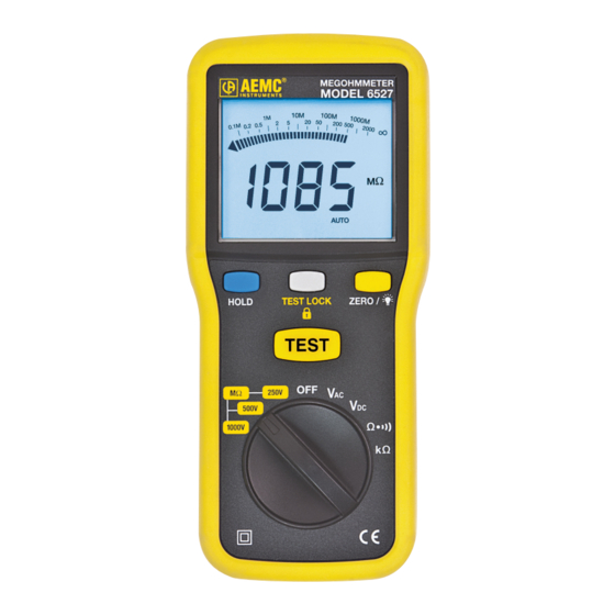
Control Features MEGOHMMETER MODEL 6527 ∞ HOLD TEST LOCK ZERO / TEST MΩ 250V 500V 1000V Figure 2-1 1. VΩ Jack / COM input jack 2. LCD Display (see § 2.4) 3. Data Hold, Test Lock and Zero/Backlight buttons (see § 2.5) 4. Rotary Function Switch (see § 2.7) Megohmmeter Model 6527 0.561.8187 information@itm. www. .com... -
Page 11: Display
Continuity measurement with buzzer HOLD Locking of the display Indicates the battery is low and must be replaced (see § 4.1) Giga- Mega- Kilo- Volt Ω Alternating current Direct current Indicates overload on the measured signal Megohmmeter Model 6527 0.561.8187 information@itm. www. .com... -
Page 12: Button Functions
NOTE: Press the button down until the insulation TEST 500V measurement is stabilized. After each measurement, the 1000V HOLD symbol is displayed. Auto-OFF Function The Model 6527 automatically turns off after 10 minutes of non-use. At 9 minutes, five beeps warn that the unit is about to be turned off. To turn the megohmmeter back on, turn the rotary switch to OFF, then to the desired function. NOTE: Auto-off can be deactivated by pushing the HOLD button when turning the rotary switch ON. Megohmmeter Model 6527 0.561.8187 information@itm. www. .com... -
Page 13: Range Switch Positions
Insulation measurement at 1000V 500V Insulation measurement at 500V 250V Insulation measurement at 250V Turns the instrument OFF AC voltage measurement (V) DC voltage measurement (V) Continuity measurement with buzzer kΩ Resistance measurement Megohmmeter Model 6527 0.561.8187 information@itm. www. .com... -
Page 14: Operation
3.3.1 Test Voltage No published standard tells which voltage to choose for any given test. However, published recommendations could be summarized as follows: Rated Voltage of Motor Test Voltage Below 115 250V 250V or 500V 500V 500V or 1000V Table 3-1 Megohmmeter Model 6527 0.561.8187 information@itm. www. .com... -
Page 15: Spot Testing
Insulation Resistance of Rotating Machinery), but this varies with tem- perature and humidity. 3.3.3 Ratio Testing In timed resistance testing (Dielectric Absorption Ratio), readings are taken at 30 and 60 seconds to obtain the dielectric absorption ratio. Insulation resistance @ 60s = Dielectric Absorption Ratio (DAR) Insulation resistance @ 30s This test is useful to increase the accuracy of spot testing. In general, a ratio of 1.25:2 or better should be required. A ratio below this indicates that repair is probably needed. Remember, a DC insulation test may be used for acceptance testing, but is more commonly used to check the gradual deterioration of equipment over its life. Consult your equipment manufacturer for specific test or test voltage if not known. Insulation resistance decreases with moisture, temperature and age and should be recorded over time at a given temperature and corrected. Megohmmeter Model 6527 0.561.8187 information@itm. www. .com... -
Page 16: Tips For Successful Insulation Resistance Testing
• Observe consistent test time duration, recognizing that total current through insulation under test will vary with time. • Correct all readings properly to a standard reference temperature (see IEEE Std. #43-1974, Temperature Correction Curve). • Know what you are testing. Isolate the piece of equipment from other circuitry. • Watch trends rather than relying on single “spot” readings. 3.3.5 Insulation Measurement - Connections Figure 3-1 shows the connections to measure the insulation of one con- ductor to the other conductors. The cable should be disconnected at both ends to avoid leakage through switchboards and panels. Conductor Under Test Cable Insulation Figure 3-1 Megohmmeter Model 6527 0.561.8187 information@itm. www. .com... - Page 17 Figures 3-2 and 3-3 show the connections for testing insulation from a supply conductor to ground (e.g. a motor frame). Conductor Under Test Cable Insulation Figure 3-2 Conductor Under Test Cable Insulation Figure 3-3 Megohmmeter Model 6527 0.561.8187 information@itm. www. .com...
- Page 18 This gives a reading of all conductors at once. If a load such as a motor, heater, etc., is attached to the other end of the line, it will read the load resistance to ground at the same time. By removing the jumpers, readings can be made between the individ- ual conductors and ground. Figure 3-5 Megohmmeter Model 6527 0.561.8187 information@itm. www. .com...
-
Page 19: Insulation Resistance Measurements On Motors
By connecting the mego- hmmeter as shown, the phase insulation resis- tance value can now be determined. Read between phases Figure 3-7 “A” and “B”, then “B” and “C”, then “C” and “A”. Megohmmeter Model 6527 0.561.8187 information@itm. www. .com... - Page 20 Figure 3-8 shows connec- Motor Side of Switch: tions for testing insulation Connection to One Leg from a supply conductor in a switchbox to ground (motor frame). An identical test Starter In may be carried out from the motor starter. Grounded Motor Frame Figure 3-8 Megohmmeter Model 6527 0.561.8187 information@itm. www. .com...
-
Page 21: Measuring Mω Insulation Resistance
Press the TEST button and hold it down until the measurement is stabilized. The display is automatically locked (automatic HOLD). The symbol lights during the measurement indicating active voltage output. • The measured resistance value is displayed on the screen. The HOLD symbol is lit. Figure 3-9 Megohmmeter Model 6527 0.561.8187 information@itm. www. .com... -
Page 22: Voltage Measurements
Voltage Measurements • Turn the function switch to the V or V range, accordingly. • Connect the black test lead to the (COM) terminal and the red one to the (VΩ) terminal. • Connect to the sample under test. 600V CAT IV Figure 3-10 Megohmmeter Model 6527 0.561.8187 information@itm. www. .com... -
Page 23: Continuity Measurements
Warning: Tests are to be carried out on non-energized circuits only! The Model 6527 generates a 200mA current between the VΩ and COM terminals. It then measures the voltage across the two terminals and from it deduces the value of R = V/I. • Turn the function switch to • Connect the black test lead to the (COM) terminal and the red one to the (V-Ω) terminal. • Connect to the sample under test. • The megohmmeter will continue generating a test current (200mA) until it is switched out of the continuity function. Turn the megohmme- ter OFF when finished and before touching the lead ends. • When there are inductive or capacitive elements in the tested sample, it may be useful to invert the polarity by switching the leads around on the sample. Take both measurements and use their average as a measurement result. Figure 3-11 Megohmmeter Model 6527 0.561.8187 information@itm. www. .com... -
Page 24: Lead Resistance Compensation
NOTE: Valid in V , Ω and kΩ positions only Resistance Measurements The Model 6527 generates a DC voltage between the V-Ω and COM terminals. It then measures the current across these two terminals and from it calculates the value of R=V/I. • Turn the range switch to kΩ. The test voltage is generated without pressing the test button. -
Page 25: Maintenance
WARNING: Make sure that no terminals are connected and that the switch is in the OFF position before opening the back of the instrument. The symbol indicates that the batteries are low and must be replaced. When this symbol appears on the display unit, the instrument continues to operate for a few minutes, and then turns itself off. To replace the batteries, proceed as follows: • Set the switch to OFF. • Disconnect the measurement leads from the input terminals. • Using a screwdriver, unscrew the three screws of the battery com- partment cover located on the back of the housing. • Place the new batteries in the compartment making sure that the polarities are correct. • Screw the cover back onto the housing. Megohmmeter Model 6527 0.561.8187 information@itm. www. .com... -
Page 26: Fuse Replacement
WARNING: Make sure that no terminals are connected and the range switch is in the OFF position. • Clean the body of the instrument with a cloth lightly moistened with soapy water. • Wipe clean with a damp cloth. • Dry with a dry cloth or forced air. • Do not use alcohol, solvents or hydrocarbons. Megohmmeter Model 6527 0.561.8187 information@itm. www. .com... -
Page 27: Specifications
1mA test current into a 1MΩ load AC VOLTAGE TRMS Range 600V 1000V Resolution Accuracy 1.2% ± 10cts Input Impedance 10MΩ (40/400Hz) DC VOLTAGE Range 600V 1000V Resolution Accuracy 0.8% ± 3cts Input Impedance 10MΩ Megohmmeter Model 6527 0.561.8187 information@itm. www. .com... - Page 28 IEC-61557-1/-2/-4:2007 and IEC-61557-10:2000 Protection Degree IP51 (EN-60529) Double Insulated CE Approved (1) Limited to 600Vrms for EN-61010-1 CAT IV (2) After compensation of lead resistance Specifications are subject to change without notice. Megohmmeter Model 6527 0.561.8187 information@itm. www. .com...
- Page 29 0.561.8187 information@itm. www. .com...
-
Page 30: Limited Warranty
CSA Form. Please write the CSA# on the outside of the shipping container. Return the instrument, postage or shipment pre-paid to: Ship To: Chauvin Arnoux , Inc. d.b.a. AEMC Instruments ® ® 15 Faraday Drive • Dover, NH 03820 USA Phone: (800) 945-2362 (Ext. 360) (603) 749-6434 (Ext. 360) Fax: (603) 742-2346 or (603) 749-6309 E-mail: repair@aemc.com Caution: To protect yourself against in-transit loss, we recommend you insure your returned material. NOTE: You must obtain a CSA# before returning any instrument. Megohmmeter Model 6527 0.561.8187 information@itm. www. .com... - Page 31 Megohmmeter Model 6527 0.561.8187 information@itm. www. .com...
- Page 32 05/13 99-MAN 100363 v4 Chauvin Arnoux , Inc. d.b.a. AEMC Instruments ® ® 0.561.8187 information@itm. www. .com...
Need help?
Do you have a question about the 6527 and is the answer not in the manual?
Questions and answers