Advertisement
Quick Links
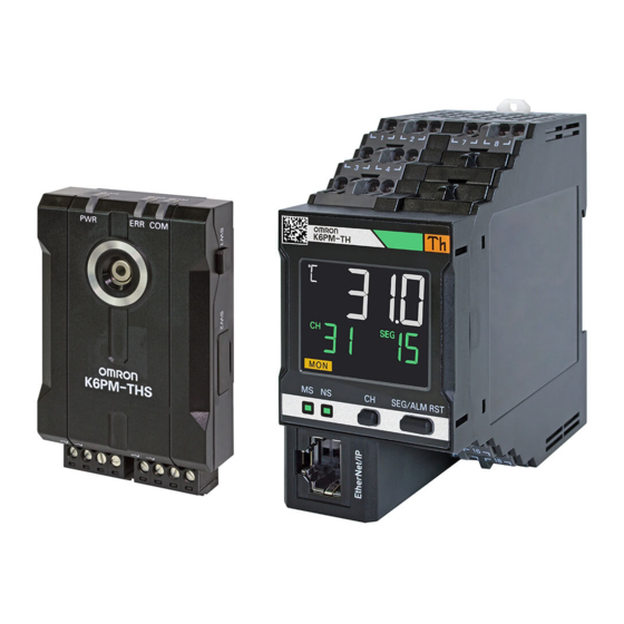
Thermal Condition
Monitoring Device
K6PM-TH
Startup Guide
0
Purpose of this guide
Step
1
Confirmation of details
Step
Preparation of necessary
2
Step
items
Installation of dedicated
3
Step
tool
4
PC IP address setting
Step
5
Hardware SW setting
Step
6
Connection
Step
Device setting with
7
Step
dedicated tool
8
How to use dedicated tool
Step
Appendices
Auto saving of log file
Advertisement

Subscribe to Our Youtube Channel
Related Manuals for Omron K6PM-TH


Summary of Contents for Omron K6PM-TH
- Page 1 Thermal Condition Monitoring Device K6PM-TH Startup Guide Purpose of this guide Step Confirmation of details Step Preparation of necessary Step items Installation of dedicated Step tool PC IP address setting Step Hardware SW setting Step Connection Step Device setting with...
- Page 2 For details of functions, refer to the "Thermal Condition Monitoring Device K6PM User's Manual (H231-E1)". As minimum configuration, one unit of K6PM-TH (hereinafter referred to as "Main Unit") and 1 unit of K6PM-THS (hereinafter referred to as "sensor") are configured.
- Page 3 Conformance to Safety Standards OMRON EUROPE B.V. (Importer in EU) Omron Companies shall not be responsible for conformity with any standards, • Reinforced insulation is provided between input power supply, output, and between other Wegalaan 67-69, NL-2132 JD Hoofddorp The Netherlands codes or regulations which apply to the combination of the Product in the Buyer’s...
- Page 4 Your computer may be set to show a User Account Control message box during installation. If there is no problem, click the [Yes] Button. (1) Download the software tool from our website. https://www.ia.omron.com/k6pm_tool (2) Run "setup.exe" in the downloaded software. The Select Language dialog box appears.
- Page 5 (3) Select Japanese or English, and click the [OK] Button. Note. If you select Japanese on a computer whose operating system is not Japanese, text may not display correctly during installation or the software tool may not operate correctly. (4) Install Microsoft .NET Framework 4.7.2. (If already installed, go to step 5.)
- Page 6 (5) Click the [Next] Button, read the Product license agreement, and if you agree to all terms of the agreement, select the I agree to all terms check box and click the [Next] Button. The User Information dialog box appears. (6) Register your user information, enter the license key, and click the [Next] Button.
- Page 7 (7) Make sure the registered information is correct, and click the [Yes] Button. The Ready to Install dialog box appears. (8) Click the [Install] Button. Installation of the software tool starts. When installation is completed, the message below appears in the Installation Wizard. (9) Click the [Finish] Button.
- Page 8 Step PC IP address setting Set the PC IP address. Set the IP address to which of the same segment as the K6PM Main Unit. Windows 7 (1) Select [Start] | [Control Panel] | [Network and Internet] | [Network and Sharing Center] | [Change Adapter Settings]. (2) Right-click [Loca Area Connection] and select [Properties].
- Page 9 Hardware SW setting Step K6PM-THS sensor has DIP switch to set the following contents. K6PM-TH Main Unit does not have hardware SW. Setting contents Value 1 to 5 K6PM-TH sensor number setting Set in binary with ON as 1 and OFF as 0 (Pin 1: Least significant bit,...
- Page 10 Connection Step ● Connect the power supply, K6PM-TH Main Unit and K6PM-THS sensor as follows. L 2 」 L 7 」 L 8 」 L 1 」 L 3 」 L 4 」 The length of the RS-485 wiring between the Main Unit and infrared thermal sensors is 500 m max.
- Page 11 (1) Start the software tool with the following method. Select All Programs - OMRON - Thermal condition Monitoring Tool from the Windows Start Menu. Or double-click the shortcut icon of the Thermal condition Monitoring Tool on the desktop.
- Page 12 (4) Click the [Setting] Button to display [K6PM_01] Screen. ● When the IP Address Is Not Set When the IP address of the target Main Unit is not set, the following dialog box appears. In this case, only the [Set IP] Button and [Device List] Button are enabled.
- Page 13 (8) Set as follows on IP address setting screen. After setting, click the "Next" Button. (9) Click the [Execute] Button.
- Page 14 At first, the configuration of dedicated tool is explained as follows. The dedicated tool mainly has two mode "setting mode" and "monitoring mode". "Setting mode" is that set the K6PM-TH Main Unit and adjust the sensor position. And then, actually operate by "monitoring mode".
- Page 15 1 Confirmation of the sensor connection and Main Unit setting [Setting Mode] (1) Click the below [Setting Mode] Button. (2) If the target sensor No. is confirmed to be connected, "ü" is attached. Select the item of "Set value" and click the [Write] Button, it will be saved in K6PM Main Unit. Reference destination of Item Description...
- Page 16 2 Sensor position adjustment [Setting Mode] (1) Click the below [Details] Button. If the angle deviation is occurred and the position is not registrated, is occurred. (2) The thermal image is displayed. It is updated at 1 s cycle. Adjust the sensor position according to the thermal image which indicates the "relationship between measurement surface and distance"...
- Page 17 Reference Relationship between the Measurement Surface and Measured Distance In order to measure the temperature more correctly, as shown in the figure below, install the infrared thermal sensor at a distance where the measurement object can be captured as a large image, as far as possible at the center of the field of view.
- Page 18 3 Switch to Monitoring Mode [Setting Mode] Click the [Start monitoring] Button in the lower light corner.
- Page 19 4 Monitoring screen configuration [Monitoring Mode] Monitoring Mode has three screens as follows. "Device List of K6PM" Screen The information of multiple K6PM-TH Main Unit can be confirmed at once. "Monitoring K6PM" Screen The information of sensor connected any K6PM-TH Main Unit can be confirmed at once.
- Page 20 5 Alarm Threshold Setting [Monitoring Mode] The threshold value is set in "Monitoring sensor" Screen. (1) Click the below [Monitoring Mode] Button to switch "Monitoring K6PM" Screen. (2) Click the below [Details] Button to switch "Monitoring sensor" Screen. (3) Select the below [Threshold set] Tub.
- Page 21 (4) The below area flamed by red square is where the threshold is set. Enter the threshold value, the background color of the cell will change to blue. During this state, click the lower right [Write] Button to set the threshold value to K6PM Main Unit. The threshold value can be set automatically.
- Page 22 During interruption: During measurement interruption due to the input of an external trigger • Communications status with the Main Unit : Normal, : Error • K6PM-TH sensor error occurrence state : Sensor type error, : Temperature measurement range exceeded, : K6PM-TH sensor angle deviation detected, : K6PM-TH sensor communications error If there is the error, click [Monitoring] Button to confirm the details.
- Page 23 • Communications: Communications status of the Main Unit and the infrared thermal sensor : Normal, : Error • Sensor: The K6PM-TH sensor error occurrence state is displayed by any of the following icons. : Sensor type error, : Temperature measurement range exceeded, : K6PM-TH sensor angle deviation detected If there is the error, click [Details] Button to confirm the details.
- Page 24 (3) Confirm whether the error per segment is occurred or not on "Monitoring sensor" Screen. Confirm which segment the error is occurred. Temperature and The following is displayed for each segment: alarm occurrence • 00 to 15: Segment number in the field of view of each infrared thermal sensor. state of each segment •...
- Page 25 The software tool saves the following data acquired from the Main Unit to be monitored in each sampling cycle in a tab- delimited text file (.txt file). • Current temperature per segment and maximum temperature per segment • K6PM-TH sensor internal current temperature and maximum temperature • Infrared thermal sensor status • Main Unit status •...
- Page 26 OMRON AUTOMATION AMERICAS HEADQUARTERS • Chicago, IL USA • 847.843.7900 • 800.556.6766 • automation.omron.com OMRON CANADA, INC. • HEAD OFFICE OMRON ELETRÔNICA DO BRASIL LTDA • HEAD OFFICE Toronto, ON, Canada • 416.286.6465 • 866.986.6766 • automation.omron.com São Paulo, SP, Brasil • 55.11.2101.6300 • www.omron.com.br OMRON ELECTRONICS DE MEXICO •...
Need help?
Do you have a question about the K6PM-TH and is the answer not in the manual?
Questions and answers