Burkert 8695 Operating Instructions Manual
Hide thumbs
Also See for 8695:
- Quick start manual (38 pages) ,
- Operating instructions manual (68 pages)
Table of Contents
Advertisement
Quick Links
Advertisement
Table of Contents

Related Manuals for Burkert 8695


Summary of Contents for Burkert 8695
- Page 1 Type 8695 Control Head Operating Instructions...
- Page 2 We reserve the right to make technical changes without notice. Technische Änderungen vorbehalten. Sous réserve de modifications techniques. © Bürkert Werke GmbH & Co. KG, 2008 - 2018 Operating Instructions 1805/10_EU-EN_00805569 / Original DE...
-
Page 3: Table Of Contents
Type 8695 Control head Type 8695 able of onTenTs OPERATING INSTRUCTIONS ...............................7 Symbols ......................................7 Definition of term / abbreviation ...........................7 AUTHORIZED USE .....................................8 Restrictions ....................................8 BASIC SAFETY INSTRUCTIONS ..............................9 GENERAL INFORMATION ................................10 Contact address ..................................10 Warranty ....................................10 Trademarks.....................................10 Information on the internet ............................10 SYSTEM DESCRIPTION ................................11... - Page 4 INSTALLATION ....................................17 Safety instructions ................................17 Installation of the control head Type 8695 on process valves of series 21xx (Element) ....17 Installation of the control head Type 8695 on process valves of series 20xx (Classic) ....22 Rotating the actuator module on process valves of series 2100, 2101, 2000 and 2012 .....26 Rotating the control head for process valves belonging to series 20xx ..........28...
- Page 5 Type 8695 10.6.1 Status LED yellow ..........................44 10.6.2 Valve LED yellow ..........................44 10.6.3 Bus LED red and green ........................45 10.6.4 End position LEDs ..........................45 10.6.5 Jumper function ...........................46 10.6.6 Change assignment of the end position LEDs ................46 DEVICENET INSTALLATION ...............................48 11.1 Definition ....................................48...
- Page 6 Type 8695 MAINTENANCE ....................................61 DISASSEMBLY ....................................62 14.1 Safety instructions ................................62 14.2 Disassembly the control head .............................62 ACCESSORIES ....................................64 15.1 Communications software .............................64 15.2 USB interface ..................................64 15.3 Download ....................................64 PACKAGING AND TRANSPORT ...............................65 STORAGE ......................................65 DISPOSAL ......................................65 english...
-
Page 7: Operating Instructions
Designates a procedure which you must carry out. Definition of term / abbreviation The term “device” used in these instructions always stands for the control head Type 8695. In these instructions, the abbreviation “Ex” always refers to “potentially explosive”. english... -
Page 8: Authorized Use
The device is designed to be mounted on pneumatic actuators of process valves for the control of media. ▶ In the potentially explosion-risk area the control head Type 8695 may be used only according to the specification on the separate approval sticker. For use observe the additional instructions enclosed with the device together with safety instructions for the explosion-risk area. -
Page 9: Basic Safety Instructions
▶ When unscrewing and screwing in the body casing or the transparent cap, do not hold the actuator of the pro- cess valve but the connection housing of Type 8695. ▶ Do not put any loads on the body (e.g. by placing objects on it or standing on it). -
Page 10: General Information
And also on the Internet at: www.burkert.com Warranty The warranty is only valid if the control head Type 8695 is used as intended in accordance with the specified appli- cation conditions. Trademarks Brands and trademarks listed below are trademarks of the corresponding companies / associations / organizations... -
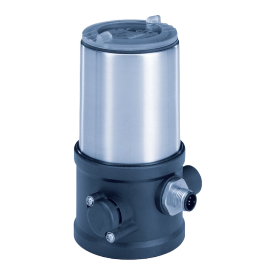
Page 11: System Description
The control head Type 8695 can control single or double-acting process valves. The control head Type 8695 has been optimized for the integrated modular fitting of series 21xx process valves (Element) with actuator size ∅ 50. Various expansion stages are possible thanks to the modular design. -
Page 12: Model For Control Of Process Valves Belonging To The 20Xx Series (Classic)
Model for control of process valves belonging to the 20xx series (Classic) A special model enables the control head Type 8695 to be attached to process valves belonging to the 20xx series. This model has a different pneumatic connection module so that the pilot air ports can be connected to the outside of the actuator (see “Figure 2”). -
Page 13: Technical Data
TECHNICAL DATA Conformity In accordance with the EU Declaration of conformity, the control head Type 8695 is compliant with the EU Directives. Standards The applied standards on the basis of which compliance with the EU Directives is confirmed are listed in the EU- Type-Examination Certificate and/or the EU Declaration of Conformity. -
Page 14: Type Labels
2 – 44 mm Type labels 6.6.1 Type label standard Example: Supply voltage / Control Control function - Pilot valve Type 8695 24 V/DC Max. operating pressure single act Pilot 0,6 Pmax 7 bar Tamb 0°C - +55°C Max. ambient temperature S/N 001000... -
Page 15: Ul Additional Label
Type 8695 Technical data 6.6.3 UL additional label Example: Degree of protection Type 4X enclosure Circuit with limited power NEC Class 2 only Supply voltage device Supply voltage: 24 V Figure 5: UL additional label (example) Pneumatic data Control medium... -
Page 16: Electrical Data
Type 8695 Technical data Electrical data WARNING! Only circuits with limited power may be used for UL approved components according to “NEC Class 2”. 6.8.1 Electrical data without bus control 24 V DC Protection class 3 as per DIN EN 61140 (VDE 0140-1) -
Page 17: Installation
Risk of injury from unintentional activation of the system and an uncontrolled restart. ▶ Secure system from unintentional activation. ▶ Following assembly, ensure a controlled restart. Installation of the control head Type 8695 on process valves of series 21xx (Element) NOTE! When mounting on process valves with a welded body, follow the installation instructions in the operating instructions for the process valve. - Page 18 Type 8695 Installation → For version with plug-in hose connector, remove the collets (white nozzles) from both pilot air ports (if present). Puck Switch spindle Guide element Groove ring max. 1 Nm max. 5 Nm Actuator cover O-ring Spindle extension...
- Page 19 Type 8695 Installation 2. Install sealing rings → Pull the form seal onto the actuator cover (smaller diameter points upwards). → Check that the O-rings are correctly positioned in the pilot air ports. When the control head is being installed, the collets of the pilot air ports must not be fitted to the actuator.
- Page 20 Type 8695 Installation 3. Install control head NOTE! Damaged printed circuit board or malfunction. ▶ Ensure that the puck is situated flat on the guide rail. → Align the puck and the control head until 1. the puck can be inserted into the guide rail of the control head 2.
- Page 21 Type 8695 Installation → Push the control head, without turning it, onto the actuator until no gap is visible on the form seal. NOTE! Too high torque when screwing in the fastening screw does not ensure degree of protection IP65 / IP67.
-
Page 22: Installation Of The Control Head Type 8695 On Process Valves Of Series 20Xx (Classic)
Type 8695 Installation Installation of the control head Type 8695 on process valves of series 20xx (Classic) Procedure: 1. Install switch spindle Transparent cap Position indicator Actuator Figure 11: Installation of the switch spindle (1), series 20xx → Unscrew the transparent cap on the actuator. - Page 23 Type 8695 Installation 2. Install control head Guide rail Puck Guide rail Puck Figure 13: Aligning the puck, series 20xx NOTE! Damaged printed circuit board or malfunction. ▶ Ensure that the puck is situated flat on the guide rail. →...
- Page 24 Type 8695 Installation Fastening screws maximum 1.5 Nm Figure 14: Installing the control head, series 20xx NOTE! Too high torque when screwing in the fastening screw does not ensure degree of protection IP65 / IP67. ▶ The fastening screws may be tightened to a maximum torque of 1.5 Nm only.
- Page 25 ▶ To comply with degree of protection IP65 / IP67, connect the pilot air outlet (only for CFA or CFB) which is not required to the free pilot air port of the actuator or seal with a plug. “In rest position” means that the pilot valves of the control head Type 8695 are isolated or not actuated. Control function A (CFA)
-
Page 26: Rotating The Actuator Module On Process Valves Of Series 2100, 2101, 2000 And 2012
Type 8695 Installation Control function I (CFI) Process valve closed in rest position Control head Pilot air outlet Actuator Upper pilot air port Lower pilot air port Process valve open in rest position Control head Pilot air outlet Actuator Upper pilot air port... - Page 27 Type 8695 Installation DANGER! Risk of injury from high pressure in the equipment/device. ▶ Before working on equipment or device, switch off the pressure and deaerate/drain lines. Procedure: → Clamp valve body in a holding device (only required if the process valve has not yet been installed).
-
Page 28: Rotating The Control Head For Process Valves Belonging To Series 20Xx
Type 8695 Installation Rotating the control head for process valves belonging to series 20xx If the connecting cables or hoses cannot be fitted properly following installation of the process valve, the control head can be rotated contrary to the actuator. -
Page 29: Manual Actuation Of The Actuator Via Pilot Valves
Type 8695 Installation Manual actuation of the actuator via pilot valve The actuator can be moved without a power supply from the rest position to its end position and back again, when the control air is connected. To do this, the pilot valve must be actuated with a screwdriver. -
Page 30: Pneumatic Installation
Type 8695 Pneumatic installation PNEUMATIC INSTALLATION DANGER! Risk of injury from high pressure in the equipment/device. ▶ Before working on equipment or device, switch off the pressure and deaerate/drain lines. Risk of electric shock. ▶ Before working on equipment or device, switch off the power supply and secure to prevent reactivation. - Page 31 Type 8695 Pneumatic installation Pilot air port (label: 1) Exhaust air port (label: 3) Figure 20: Pneumatic connection Caution: (Air exhaust concept): In compliance with degree of protection IP67, an air exhaust line must be installed in the dry area.
-
Page 32: Electrical Installation 24 V Dc
Type 8695 Electrical installation 24 V DC ELECTRICAL INSTALLATION 24 V DC The kind of connection is used for the electrical bonding of the control head: • Multi-pole with circular plug-in connector M12 x 1, 8-pole Safety instructions DANGER! Risk of electric shock. -
Page 33: Electrical Installation
Type 8695 Electrical installation 24 V DC Electrical installation Configuration circular plug (M12 x 1, 8-pole): Figure 21: Circular plug M12 x 1, 8-pole Wire color Designation Configuration External circuit / signal level + 24 V white limit switch top... -
Page 34: Teach Function (Calibrating The End Position)
Type 8695 Electrical installation 24 V DC Teach function (calibrating the end position) The teach function can be used to automatically determine and read in the end positions of the valve. DANGER! Risk of electric shock. ▶ Before working on equipment or device, switch off the power supply and secure to prevent reactivation. - Page 35 Type 8695 Electrical installation 24 V DC → The key in recess for actuating the Teach function keep pressed for approximately 5 seconds. NOTE! Breakage of the pneumatic connection pieces due to rotational impact. ▶ When unscrewing and screwing in the transparent cap, do not hold the actuator of the process valve but the connection housing.
-
Page 36: Display And Control Elements 24 V Dc
Type 8695 Electrical installation 24 V DC Display and control elements 24 V DC End position LED green Jumper for assignment of end position LEDs End position LED yellow Status LED yellow Valve LED yellow (pilot valve) Figure 24: Description LED and Jumpers - 24 V DC NOTE! Breakage of the pneumatic connection pieces due to rotational impact. -
Page 37: End Position Led Green And Yellow
Type 8695 Electrical installation 24 V DC 9.4.3 End position LED green and yellow Factory setting: Color Device status green LED on End position bottom yellow LED on End position top Table 5: Assignment of end position LEDs - 24 V DC 9.4.4... - Page 38 Type 8695 Electrical installation 24 V DC → Using the jumpers, assign the required color to the end position LEDs. Jumper setting 1: In the end position top (Top), End position LED green the yellow LED is lit; in the end position bottom (Bot), the green LED is lit.
-
Page 39: As-Interface Installation
Type 8695 AS-Interface installation AS-INTERFACE INSTALLATION 10.1 AS-Interface connection AS-Interface (Actuator Sensor Interface) is a field bus system which is used primarily for networking binary sensors and actuators (slaves) with a higher-level control (master). Bus line Unshielded two-wire line (AS-Interface line as AS-Interface cable harness) along which both information (data) and energy (supply voltage for the actuators and sensors) are transmitted. -
Page 40: Electrical Installation As-Interface
Type 8695 AS-Interface installation 10.4 Electrical installation AS-Interface 10.4.1 Safety instructions DANGER! Risk of electric shock. ▶ Before working on equipment or device, switch off the power supply and secure to prevent reactivation. ▶ Observe applicable accident prevention and safety regulations for electrical equipment. -
Page 41: Connection With Multi-Pole Cable And Ribbon Cable Terminal
M12 4-pole circular plug and can easily be connected to the ribbon cable terminal (see “Figure 31”). Figure 30: Control head 8695 with multi-pole cable and ribbon cable terminal Handling the ribbon cable terminal The multi-pole cable features a ribbon cable terminal - with M12 plug-in connector branch circuit - for AS-Interface cable harness. -
Page 42: Teach Function (Calibrating The End Position)
Type 8695 AS-Interface installation 10.5 Teach function (calibrating the end position) The teach function can be used to automatically determine and read in the end positions of the valve. For the bus variant AS-Interface, the teach function can also be started via the bus protocol. - Page 43 Type 8695 AS-Interface installation → The key in recess for actuating the teach function keep pressed for approximately 5 seconds. Chronological description of the teach function: Key in recess for • the bottom position is read in internally actuating the teach • the pilot valve switches...
-
Page 44: Display And Control Elements As-Interface
Type 8695 AS-Interface installation 10.6 Display and control elements AS-Interface Bus LED red Bus LED green Status LED yellow Valve LED yellow (pilot valve) Figure 34: Description LED and Jumper - AS-Interface NOTE! Breakage of the pneumatic connection pieces due to rotational impact. -
Page 45: Bus Led Red And Green
Type 8695 AS-Interface installation 10.6.3 Bus LED red and green The red and green LEDs (bus) indicate the bus status: LED green LED red POWER OFF No data traffic (expired Watch Dog at slave address does not equal 0) flashing... -
Page 46: Jumper Function
Type 8695 AS-Interface installation Factory setting: Color Device status green LED on End position bottom yellow LED off End position top Table 11: Assignment of LEDs - AS-Interface 10.6.5 Jumper function You can set the color assignment of the end positions with the jumpers. - Page 47 Type 8695 AS-Interface installation Transparent cap Body casing Connection housing Actuator Figure 39: Open control head → Using the jumpers, assign the required color to the LEDs (see “Figure 38: Assignment of the end position LED - AS-Interface”). NOTE! Damage or malfunction due to penetration of dirt and humidity.
-
Page 48: Devicenet Installation
Address 0 – 63 (via DIP switches); Factory setting: 63 Process data 1 static input assembly (input: from the control head 8695 to the DeviceNet Master/Scanner) 1 static output assembly 11.3 Maximum line lengths The maximum total line length (sum of trunk lines and drop lines) of a network depends on the baudrate. -
Page 49: Drop Line Length
If the bus fails, the pilot valve is switched to a programmable safety setting (default: pilot valve isolated). For con- figuration data see chapter entitled “11.9 Configuring the control head”. 11.5 Interfaces Control head 8695 Bus + supply DeviceNet 11.6 Electrical connection DeviceNet The bus line is a 4-core cable with additional shielding which must conform to the DeviceNet specification. -
Page 50: Display And Control Elements Devicenet
Type 8695 DeviceNet installation 11.6.2 Display and control elements DeviceNet RS232 End position LED green Device status LED (two-colored: red/green) End position LED yellow DIP switches for bus address and baudrate Bus LED (two-colored: red/green) Valve LED yellow (pilot valve) -
Page 51: Network Topology Of A Devicenet System
Type 8695 DeviceNet installation 11.8 Network topology of a DeviceNet system Line with a trunk line and several drop lines. Trunk lines and drop lines consist of identical material (see “Figure 42”). Trunk line DeviceNet cable V – CAN_H CAN_L... - Page 52 Type 8695 DeviceNet installation Procedure: NOTE! Breakage of the pneumatic connection pieces due to rotational impact. ▶ When unscrewing and screwing in the transparent cap, do not hold the actuator of the process valve but the connection housing. → Open the control head: turning the transparent cap anti-clockwise.
-
Page 53: 11.10 Configuration Of The Process Data
Type 8695 DeviceNet installation Setting the baudrate Adjusting the control head to the baudrate of the network. DIP 7 DIP 8 Baudrate 125 kbaud 250 kbaud 500 kbaud not permitted Table 16: Setting the baudrate Please note: If the settings are changed by actuating the DIP switches, this change will not take effect until the device is restarted. -
Page 54: Configuration Of The Safety Position Of Pilot Valves For Bus Error
Type 8695 DeviceNet installation 11.11 Configuration of the safety position of pilot valves for bus error If a bus fault occurs, the bus LED may assume the “Green flashing”, “Red flashing” or “Red” status. (For a description see “Status of the bus LED”, page 59) The valve safety position and safety module attributes can be used to configure the pilot valve in the event of a bus fault. - Page 55 Type 8695 DeviceNet installation Key in recess for actuating the teach function (keep pressed for approximately 5 seconds Chronological description of the teach function: • the bottom position is read in internally • the pilot valve switches • the actuator moves automatically to the top position • the top position is read in internally...
- Page 56 Type 8695 DeviceNet installation NOTE! Breakage of the pneumatic connection pieces due to rotational impact. ▶ When unscrewing and screwing in the transparent cap, do not hold the actuator of the process valve but the connection housing. Damage or malfunction due to penetration of dirt and humidity.
-
Page 57: 11.12.1 Starting The Teach Function
Type 8695 DeviceNet installation 11.12.1 Starting the teach function DANGER! Danger due to the valve position changing when the teach function is running. When the teach function is running under operating pressure, there is an acute risk of injury. ▶ Never run the teach function while a process is running. -
Page 58: 11.13 Display Elements Devicenet
Type 8695 DeviceNet installation 11.13 Display elements DeviceNet End position LED green Device status LED (two-colored: red/green) End position LED yellow Status LED (yellow) Bus LED (two-colored: red/green) Valve LED yellow (pilot valve) Figure 48: Display elements - DeviceNet NOTE! Breakage of the pneumatic connection pieces due to rotational impact. -
Page 59: 11.13.1 Device Status Led And Bus Led
Type 8695 DeviceNet installation 11.13.1 Device status LED and bus LED Function test of the device status LED and bus LED When voltage has been applied (connection of the network line), the following function test is run for the two- colored device status LED and bus LED: • LED is briefly lit green (approx. -
Page 60: 11.13.2 End Position Leds
Type 8695 DeviceNet installation 11.13.2 End position LEDs The end positions are displayed optically by colored LEDs. The following functions are shown as standard Color Device status green end position LED on End position bottom yellow end position LED on... -
Page 61: Safety Positions
Control function A down single-acting Control function B down double-acting down not defined Control function B down Table 27: Safety Positions MAINTENANCE The control head Type 8695 is maintenance-free when operated according to the instructions in this manual. english... -
Page 62: Disassembly
Type 8695 Disassembly DISASSEMBLY 14.1 Safety instructions DANGER! Risk of injury from high pressure in the equipment/device. ▶ Before working on equipment or device, switch off the pressure and deaerate/drain lines. Risk of electric shock. ▶ Before working on equipment or device, switch off the power supply and secure to prevent reactivation. - Page 63 Type 8695 Disassembly 2. Electrical connection DANGER! Risk of electric shock. ▶ Before working on equipment or device, switch off the power supply and secure to prevent reactivation. ▶ Observe applicable accident prevention and safety regulations for electrical equipment. →...
-
Page 64: Accessories
15.1 Communications software The PC operating program “Communicator” is designed for communication with the devices Type 8695 with bus control via DeviceNet. Devices constructed since April 2014 support the full range of functions. If you have any questions regarding compatibility, please contact the Bürkert Sales Center. -
Page 65: Packaging And Transport
Type 8695 Packaging and transport PACKAGING AND TRANSPORT NOTE! Transport damages. Inadequately protected equipment may be damaged during transport. ▶ During transportation protect the device against wet and dirt in shock-resistant packaging. ▶ Avoid the effects of heat and cold which could result in temperatures above or below the permitted storage temperature. - Page 67 www.burkert.com...
Need help?
Do you have a question about the 8695 and is the answer not in the manual?
Questions and answers