Burkert 8695 Operating Instructions Manual
Control head
Hide thumbs
Also See for 8695:
- Quick start manual (38 pages) ,
- Operating instructions manual (67 pages)
Table of Contents
Advertisement
Quick Links
Advertisement
Table of Contents

Related Manuals for Burkert 8695


Summary of Contents for Burkert 8695
- Page 1 Type 8695 REV.3 Control Head Operating Instructions...
- Page 2 We reserve the right to make technical changes without notice. Technische Änderungen vorbehalten. Sous réserve de modifications techniques. © Bürkert Werke GmbH & Co. KG, 2022 Operating Instructions 2209/00_EU-EN_00815434 / Original DE...
-
Page 3: Table Of Contents
Type 8695 REV.3 Control head Type 8695 REV.3 able of onTenTs ABOUT THESE INSTRUCTIONS ......................7 Symbols ............................7 1.2 Definition of terms ........................7 INTENDED USE ............................8 BASIC SAFETY INSTRUCTIONS ......................9 GENERAL INFORMATION ........................10 Contact address .........................10 Warranty .............................10 Trademarks ..........................10 4.4 Information on the internet ......................10 SYSTEM DESCRIPTION ........................11... - Page 4 Type 8695 REV.3 Inhaltsverzeichnis 6.7.1 Electrical data without field bus communication ............16 6.7.2 Electrical data, IO-Link ....................16 6.7.3 Electrical data, büS .....................17 6.7.4 Electrical data, AS-Interface ..................17 6.8 Communication ..........................18 6.8.1 IO-Link ........................18 INSTALLATION ............................19 7.1 Safety instructions ........................19 7.2 Installation of the control head Type 8695 on process valves of series 21xx (ELEMENT) ..19 7.3 Installation of the control head Type 8695 on process valves of series 20xx (CLASSIC) ..24 7.4 Rotating the actuator module on process valves of series 2100, 2101, 2000 and 2012 ..28...
- Page 5 Type 8695 REV.3 10.4 IO-Link ............................47 10.4.1 Information, IO-Link ....................47 10.5 Configuration of the fieldbus .....................47 10.6 büS ..............................47 10.6.1 Information, büS ......................47 10.6.2 Configuration of the fieldbus ..................47 10.7 AS-Interface ..........................48 10.7.1 Certification ........................48 10.7.2 Programming data ......................48 CONTROL AND DISPLAY ELEMENTS ....................49 11.1 Operating state ..........................50 11.2 Functions of the operating and display elements ..............51 11.3 Status indicator ..........................54...
- Page 6 Type 8695 REV.3 STORAGE .............................65 DISPOSAL ............................65 english...
-
Page 7: About These Instructions
▶ Failure to observe the warning may result in damage to device or system. Indicates important additional information, tips and recommendations. Refers to information in these operating instructions or in other documentation. ▶ Indicates an instruction for risk prevention. → Indicates a procedure which you must carry out. Indicates a result. Menu Indicates a interface text. Definition of terms In these instructions the term “device” denotes the following device types: Control head Type 8695 REV.3. The term “büS” (Bürkert system bus) used in this instruction stands for the communication bus developed by Bürkert and based on the CANopen protocol. In these instructions, the abbreviation “Ex” always refers to “potentially explosive atmosphere”. english... -
Page 8: Intended Use
Type 8695 REV.3 Intended use INTENDED USE The control head Type 8695 REV.3 is designed to be mounted on pneumatic actuators of process valves for the control of media. The permitted fluid media are listed in the technical data. ▶ Use the device for its intended purpose only. Non-intended use of the device may be dangerous to peo- ple, nearby equipment and the environment. ▶ Correct transportation, correct storage as well as correct installation, commissioning, operation and maintenance are essential for reliable and problem-free operation. ▶ When using the device, observe the permitted data, operating conditions and application conditions. This information can be found in the contractual documents, the operating instructions and on the type label. ▶ Use the device only in conjunction with third-party devices and components recommended and autho- rized by Bürkert. ▶ Do not use the device outdoors without protection from the weather. ▶ In potentially explosive atmosphere, only use devices approved for use in those areas. These devices are labeled with a separate Ex type label. For such use, note the information provided on the separate Ex type label and the additional explosion-related information or separate explosion-related operating instructions. english... -
Page 9: Basic Safety Instructions
Type 8695 REV.3 Basic safety instructions BASIC SAFETY INSTRUCTIONS These safety instructions do not consider any contingencies or incidents which occur during installation, operation and maintenance. The operator is responsible for observing the location-specific safety regulations, also with reference to the personnel. DANGER Risk of injury from high pressure and discharge of medium. ▶ Before working on the device or system, switch off the pressure. Vent or drain lines. DANGER Risk of injury from electric shock. ▶ Before working on the device or system, switch off the power supply. Secure against reactivation. ▶ Observe applicable accident prevention and safety regulations for electrical equipment. To prevent injury, ensure the following: ▶ Secure device or system to prevent unintentional activation. ▶ Only trained technicians may perform installation and maintenance work. -
Page 10: General Information
Type 8695 REV.3 General information GENERAL INFORMATION Contact address Germany Bürkert Fluid Control System Chr.-Bürkert-Str. 13-17 D-74653 Ingelfingen E-mail: info@burkert.com International Contact addresses can be found on the final pages of the printed operating instructions. And also on the Internet at: www.burkert.com Warranty The warranty is only valid if the control head Type 8695 is used as intended in accordance with the specified application conditions. Trademarks Brands and trademarks listed below are trademarks of the corresponding companies / associations / organizations Loctite Henkel Loctite Deutschland GmbH Information on the internet The operating instructions and data sheets for Type 8695 can be found on the Internet at: www.burkert.com english... -
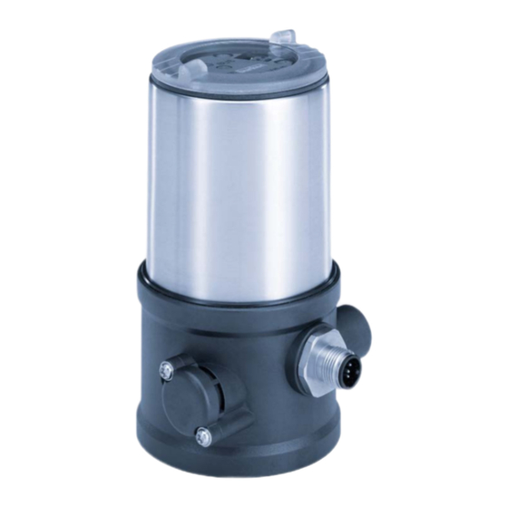
Page 11: System Description
Type 8695 REV.3 System description SYSTEM DESCRIPTION Structure and function The control head Type 8695 can control single or double-acting process valves. The control head Type 8695 has been optimized for the integrated modular fitting of series 21xx process valves (ELEMENT) with actuator size ∅ 50. Various expansion stages are possible thanks to the modular design. For installation on the 20xx series (CLASSIC) there is a special model which is described in chapter “5.1.2”. The valve position is recorded via a contactless, analog sensor element which automatically detects and saves the valve end positions by means of the teach function during start-up. Variants: • without fieldbus communication: 24 V device with digital inputs and outputs and büS service interface • AS Interface • IO-Link • büS 5.1.1... -
Page 12: Model For Control Of Process Valves Belonging To The 20Xx Series (Classic)
Type 8695 REV.3 System description 5.1.2 Model for control of process valves belonging to the 20xx series (CLASSIC) A special model enables the control head Type 8695 to be attached to process valves belonging to the 20xx series. This model has a different pneumatic connection module so that the pilot air ports can be connected to the outside of the actuator (see “Figure 2”). Pilot air outlet 2 Pilot air outlet 2 Figure 2: Model for control of process valves, 20xx series... -
Page 13: Technical Data
Type 8695 REV.3 Technical data TECHNICAL DATA Standards and directives The device complies with the relevant EU harmonisation legislation. In addition, the device also complies with the requirements of the laws of the United Kingdom. The harmonised standards that have been applied for the conformity assessment procedure are listed in the current version of the EU Declaration of Conformity/UK Declaration of Conformity. Licenses The product is approved for use in zone 2 and 22 in accordance with ATEX directive 2014/34/EU category 3GD. Observe instructions on operation in a potentially explosive atmosphere (Ex area). Observe the ATEX additional instructions. The product is cULus approved. Instructions for use in the UL area see chapter “6.7 Electrical data”. Operating conditions WARNING! Solar radiation and temperature fluctuations may cause malfunctions or leaks. ▶ If the device is used outdoors, do not expose it unprotected to the weather conditions. -
Page 14: Mechanical Data
Type 8695 REV.3 Technical data Mechanical data Dimensions See data sheet Body material e xterior PPS, PC, VA interior PA6; ABS Sealing material e xterior EPDM / FKM Stroke range of valve spindle 21xx series (ELEMENT) and 20xx series (CLASSIC) 2 – 35 mm Third-party devices (modified guide element required) 2 – 44 mm Type labels 6.5.1... -
Page 15: Ul Additional Label
Type 8695 REV.3 Technical data 6.5.3 UL additional label Degree of protection Type 4X enclosure Circuit with limited power NEC Class 2 only E238179 Communication, Power Supply: b üS supply voltage 24V ±25% max. 3,5 W Power consumption Figure 5: UL additional label (example) Pneumatic data Control medium n eutral gases, air... -
Page 16: Electrical Data
Type 8695 REV.3 Technical data Electrical data WARNING! Only circuits with limited power may be used for UL approved components according to “NEC Class 2”. 6.7.1 Electrical data without field bus communication Protection class III as per DIN EN 61140 (VDE 0140-1) Connection Supply Circular plug-in connector (M12 x 1, 8-pin) Communication büS service interface Operating voltage 24 V ± 25 %, max. residual ripple 10 %... -
Page 17: Electrical Data, Büs
Type 8695 REV.3 Technical data 6.7.3 Electrical data, büS Protection class III as per DIN EN 61140 (VDE 0140-1) Connection Circular plug-in connector M12 x 1, 5-pin, A coded Operating voltage 24 V ±25 % Current consumption m ax. 150 mA, only with installed pilot valve Total power consumption max. 3.5 W 6.7.4 Electrical data, AS-Interface Protection class III as per DIN EN 61140 (VDE 0140-1) -
Page 18: Communication
Type 8695 REV.3 Technical data Communication 6.8.1 IO-Link Port class IO-Link Specification V1.1.2 Supply via IO-Link (M12 x 1, 5-pin, A-coded) SIO mode IODD file see Internet VendorID 0x0078, 120 DeviceID see IODD file ProductID 8695 Class A 8695 Class B Transmission speed COM3 (230,4 kbit/s) PD Input Bits PD Output Bits M-sequence Cap. -
Page 19: Installation
▶ Before working on equipment or device, switch off the power supply and secure to prevent reactivation. ▶ Observe applicable accident prevention and safety regulations for electrical equipment. WARNING! Risk of injury from improper installation. ▶ Installation may be carried out by authorized technicians only and with the appropriate tools. Risk of injury from unintentional activation of the system and an uncontrolled restart. ▶ Secure system from unintentional activation. ▶ Following assembly, ensure a controlled restart. Installation of the control head Type 8695 on process valves of series 21xx (ELEMENT) ATTENTION! When mounting on process valves with a welded connection, follow the installation instructions in the operating instructions for the process valve. Procedure: 1. Install switch spindle Transparent cap Pilot air ports... - Page 20 Type 8695 REV.3 Installation → For version with plug-in hose connector, remove the collets (white nozzles) from both pilot air ports (if present). Puck Switch spindle Guide element Groove ring max. 1 Nm max. 5 Nm Actuator cover O-ring Spindle extension Figure 7: Installation of the switch spindle (2), series 21xx ATTENTION! Improper installation may damage the groove ring in the guide element. The groove ring is already be pre-assembled in the guide element and must be “locked into position” in the undercut. ▶ When installing the switch spindle, do not damage the groove ring. → Push the switch spindle through the guide element. ATTENTION! Screw locking paint may contaminate the groove ring.
- Page 21 Type 8695 REV.3 Installation 2. Install sealing rings → Pull the form seal onto the actuator cover (smaller diameter points upwards). → Check that the O-rings are correctly positioned in the pilot air ports. When the control head is being installed, the collets of the pilot air ports must not be fitted to the actuator. Pilot air ports Caution: Collets must not be fitted ! Form seal Installation of the form seal Figure 8: Installation of the sealing rings...
- Page 22 Type 8695 REV.3 Installation 3. Install control head ATTENTION! Damaged printed circuit board or malfunction. ▶ Ensure that the puck is situated flat on the guide rail. → Align the puck and the control head until 1. the puck can be inserted into the guide rail of the control head 2. the connection pieces of the control head can be inserted into the pilot air ports of the actuator.
- Page 23 Type 8695 REV.3 Installation → Push the control head, without turning it, onto the actuator until no gap is visible on the form seal. ATTENTION! Too high torque when screwing in the fastening screw does not ensure degree of protection IP65 / IP67. ▶ The fastening screws may be tightened to a maximum torque of 1.5 Nm only. → Attach the control head to the actuator using the two side fastening screws. In doing so, tighten the screws only hand-tight (maximum torque: 1.5 Nm). Fastening screws max. 1.5 Nm Connection pieces Pilot air ports (actuator)
-
Page 24: Installation Of The Control Head Type 8695 On Process Valves Of Series 20Xx (Classic)
Type 8695 REV.3 Installation Installation of the control head Type 8695 on process valves of series 20xx (CLASSIC) Procedure: 1. Install switch spindle Transparent cap Position indicator Actuator Figure 11: Installation of the switch spindle (1), series 20xx → Unscrew the transparent cap on the actuator. - Page 25 Type 8695 REV.3 Installation 2. Install control head Guide rail Puck Guide rail Puck Figure 13: Aligning the puck, series 20xx ATTENTION! Damaged printed circuit board or malfunction. ▶ Ensure that the puck is situated flat on the guide rail. → Push the control head onto the actuator. The puck must be aligned in such a way that it is inserted into the guide rail of the control head. → Press the control head all the way down as far as the actuator and turn it into the required position.
- Page 26 Type 8695 REV.3 Installation Fastening screws maximum 1.5 Nm Figure 14: Installing the control head, series 20xx ATTENTION! Too high torque when screwing in the fastening screw does not ensure degree of protection IP65 / IP67. ▶ The fastening screws may be tightened to a maximum torque of 1.5 Nm only. → Attach the control head to the actuator using the two side fastening screws. In doing so, tighten the fas- tening screws hand-tight only (maximum torque: 1.5 Nm).
- Page 27 Type 8695 REV.3 Installation 3. Install pneumatic connection between control head and actuator Pilot air outlet 2 Pilot air outlet 2 Upper pilot air port Lower pilot air port Figure 15: Installing the pneumatic connection between control head and actuator, series 20xx →...
-
Page 28: Rotating The Actuator Module On Process Valves Of Series 2100, 2101, 2000 And 2012
Type 8695 REV.3 Installation Control function I (CFI) Process valve closed in rest position Control head Pilot air outlet Actuator Upper pilot air port Lower pilot air port Process valve open in rest position Control head Pilot air outlet Actuator... - Page 29 Type 8695 REV.3 Installation DANGER! Risk of injury from high pressure in the equipment/device. ▶ Before working on equipment or device, switch off the pressure and deaerate/drain lines. Procedure: → Clamp valve body in a holding device (only required if the process valve has not yet been installed). → Control function A: Open process valve. Actuator module Hexagon Hexagon Nipple Nipple Series 2100 and 2101 Series 2000 and 2012 Figure 16: Rotating the actuator module → Using a suitable open-end wrench, counter the wrench flat on the pipe. → Place suitable open-end wrench on the hexagon of the actuator.
-
Page 30: Rotating The Control Head For Process Valves Belonging To Series 20Xx
Type 8695 REV.3 Installation Rotating the control head for process valves belonging to series 20xx If the connecting cables or hoses cannot be fitted properly following installation of the process valve, the control head can be rotated contrary to the actuator. Fastening screw (2x) Control head Pneumatic connection Actuator Figure 18: Rotating the control head, series 20xx Procedure →... -
Page 31: Pneumatic Installation
Type 8695 REV.3 Pneumatic installation PNEUMATIC INSTALLATION DANGER! Risk of injury from high pressure in the equipment/device. ▶ Before working on equipment or device, switch off the pressure and deaerate/drain lines. Risk of electric shock. ▶ Before working on equipment or device, switch off the power supply and secure to prevent reactivation. ▶ Observe applicable accident prevention and safety regulations for electrical equipment. WARNING! Risk of injury from improper installation. ▶ Installation may be carried out by authorized technicians only and with the appropriate tools. Risk of injury from unintentional activation of the system and an uncontrolled restart. ▶ Secure system from unintentional activation. ▶ Following installation, ensure a controlled restart. Procedure: → Connect the control medium to the pilot air port (1) (3 – 7 bar; instrument air, free of oil, water and dust). → Attach the exhaust airline or a silencer to the exhaust air port (3). - Page 32 Type 8695 REV.3 Pneumatic installation Pilot air port (label: 1) Exhaust air port (label: 3) Figure 19: Pneumatic connection Air exhaust concept: ▶ In compliance with degree of protection IP67, an air exhaust line must be installed in the dry area. english...
-
Page 33: Electrical Installation
Type 8695 REV.3 Electrical installation ELECTRICAL INSTALLATION Safety instructions DANGER! Risk of electric shock. ▶ Before working on equipment or device, switch off the power supply and secure to prevent reactivation. ▶ Observe applicable accident prevention and safety regulations for electrical equipment. WARNING! Risk of injury from improper installation. ▶ Installation may be carried out by authorized technicians only and with the appropriate tools. Risk of injury from unintentional activation of the system and an uncontrolled restart. ▶ Secure system from unintentional activation. ▶ Following installation, ensure a controlled restart. Minimum temperature rating of the cable to be connected to the field wiring terminals: 75 °C english... -
Page 34: Electrical Installation, Without Fieldbus Communication
Type 8695 REV.3 Electrical installation Electrical installation, without fieldbus communication Configuration circular plug (M12 x 1, 8-pin): Figure 20: Circular plug M12 x 1, 8-pin Wire color Designation Configuration External circuit / signal level Digital output end position with white DO2+ actuator activated Digital output end position with brown... -
Page 35: Electrical Installation, Io-Link Port Class B And Port Class A
Type 8695 REV.3 Electrical installation Electrical installation, IO-Link port class B and port class A Designation Configuration Port class B 24 V DC System supply 24 V DC Actuator supply L – 0 V (GND) System supply IO-Link 0 V (GND) Actuator supply... -
Page 36: Electrical Installation, As-Interface
Type 8695 REV.3 Electrical installation Electrical installation, AS-Interface 9.5.1 Connection with circular plug-in connector M12 x 1, 4-pin Bus - Bus + Table 7: Pin assignment Designation Configuration Bus + AS-Interface bus line + not assigned Bus – AS-Interface bus line – not assigned Table 8:... -
Page 37: Connection With Multi-Pole Cable And Ribbon Cable Terminal
M12 4-pole circular plug and can easily be connected to the ribbon cable terminal (see “Figure 23”) Figure 22: Control head 8695 with multi-pole cable and ribbon cable terminal Handling the ribbon cable terminal The multi-pole cable features a ribbon cable terminal - with M12 plug-in connector branch circuit - for ASIn- terface cable harness. The ribbon cable terminal contacts the AS-Interface cable harness by means of pen- etration technology which allows installation by “clipping in” the AS-Interface cable harness without cutting... -
Page 38: Start-Up
Type 8695 REV.3 Start-up START-UP WARNING! Risk of injury from improper operation. Improper operation may result in injuries as well as damage to the device and the area around it. ▶ Before start-up, ensure that the operating personnel are familiar with and completely understand the con- tents of the operating instructions. ▶ Observe the safety instructions and intended use. ▶ Only adequately trained personnel may operate the equipment/the device. 10.1 Invert process valve direction In the factory settings, the following actuator end positions and colours of the status indicator are assigned... - Page 39 Type 8695 REV.3 Start-up Invert process valve direction: Transparent cap Body casing Basic housing Actuator Figure 24: Open device ATTENTION Breakage of the pneumatic connection pieces due to rotational impact. ▶ When opening or closing the device, do not press against the actuator, but against the basic housing. →...
-
Page 40: Teach Function: Determine End Positions And Save These, Rev.3
Type 8695 REV.3 Start-up 10.2 Teach function: Determine end positions and save these, REV.3 • Automatic teach function: For devices with pilot valve The teach function automatically identifies and saves the end positions of the valve. • Manual teach function: For devices without pilot valve The end positions are captured and saved automatically. • Teach-in-operation function: The teach-in operation function (if previously activated) identifies and saves the end positions during normal operation. DANGER! Danger due to the valve position changing when the teach function is running. - Page 41 Type 8695 REV.3 Start-up ATTENTION Breakage of the pneumatic connection pieces due to rotational impact. ▶ When opening or closing the device, do not press against the actuator, but against the basic housing. → Open the device: turning the transparent cap anti-clockwise. Key 1 ASi PWR LED (green) Pilot LED Inv.ValveDir. LED ASi FAULT LED (red) büS service interface...
-
Page 42: Manual Teach Function
Type 8695 REV.3 Start-up Description of workflow for automatic teach function: The status insicator flashes orange when the teach function is running. • The first end position (POS1 = pilot valve deactivated) is scanned in. • The pilot valve switches. • The actuator moves automatically to the second end position (POS2 = pilot valve activated). • The second end position (POS2 = pilot valve activated) is scanned in. • The pilot valve is switched off. • The actuator moves to the first end position (POS1 = pilot valve deactivated). 10.2.2 Manual teach function For devices without pilot valve: The end positions are captured and saved manually by the user. - Page 43 Type 8695 REV.3 Start-up Key 1 ASi PWR LED (green) Pilot LED Inv.ValveDir. LED ASi FAULT LED (red) büS service interface Manual LED Status indicator Key 2 (RGB LED) Figure 31: Operating and display elements 10 s Start manual Status indicator teach function Inv.ValveDir.
-
Page 44: Teach-In-Operation Function
Type 8695 REV.3 Start-up 10.2.3 Teach-in-operation function The teach-in-operation function can be used if the device is to carry out the end positions of the process valve automatically during normal operation (once when the control unit is switched on for the first time). This function may only be used for process valve actuators with control function A (normally closed). The function must first be enabled via the büS service interface (Bürkert Communicator). For devices that are delivered without a process valve, this function is already enabled because no other teach function has yet been carried out. -
Page 45: Setting With Bürkert Communicator
Type 8695 REV.3 Start-up 10.3 Setting with Bürkert Communicator The Bürkert Communicator can be used to make all settings on the device. The settings in the Bürkert Communicator can be found in the operating manual. 10.3.1 Connecting IO-Link device with Bürkert Communicator Devices without fieldlbus communication, devices with IO-Link or AS-Interface via büS service interface: Required components: • Communications software: Bürkert Communicator for PC • USB-büS interface set (see accessories) •... - Page 46 Type 8695 REV.3 Start-up Key 1 ASi PWR LED (green) Pilot LED Inv.ValveDir. LED ASi FAULT LED (red) büS service interface Manual LED Status indicator Key 2 (RGB LED) Figure 34: Communication interface → Insert micro USB plug in büS service interface. → Establish connection to PC with USB-büS interface set.
-
Page 47: Io-Link
Type 8695 REV.3 Start-up 10.4 IO-Link 10.4.1 Information, IO-Link IO-Link is an internationally standardized IO technology (IEC 61131-9) to enable sensors and actuators to communicate. IO-Link is a point-to-point communication with 3-wire connection technology for sensors and actuators and unshielded standard sensor cables. To ensure clear communication, the IO-Link devices should not be parameterised simultaneously by the higher-level controller (PLC) via the IO-Link master and with the Bürkert Communicator (via the communication... -
Page 48: As-Interface
Type 8695 REV.3 Start-up 10.7 AS-Interface AS-Interface (Actuator Sensor Interface) is a field bus system which is used primarily for networking binary sensors and actuators (slaves) with a higher-level control (master). The unshielded two-wire line is used to transmit both the information (data) and the energy to supply the actuators and sensors. 10.7.1 Certification The device is certified according to AS-Interface specification version 3.0. Certificate No.: on request 10.7.2 Programming data I/O-Konfiguration B hex ID code A hex (bit configuration see above) Extended ID code 1 7 hex Extended ID code 2 E hex Profile S-B.A.E Table 11: Programming data... -
Page 49: Control And Display Elements
Type 8695 REV.3 Control and display elements CONTROL AND DISPLAY ELEMENTS Key 1 ASi PWR LED (green) Pilot LED Inv.ValveDir. LED ASi FAULT LED (red) büS service interface Manual LED Status indicator Key 2 (RGB LED) Figure 35: Operating and display elements Description of the functions Press for 5–10 s: start automatic teach function... -
Page 50: Operating State
Type 8695 REV.3 Control and display elements Description of the displays Status indicator Valve position, error, warning RGB LED see chapter „Status indicator“ Pilot LED yellow Is lit: pilot valve is actuated (on) Manual LED red Is lit: MANUAL operating state active Flashes at 10 Hz for 0–2 s: Switch MANUAL ↔ AUTO Inv.ValveDir. green Is lit: inversion of process valve direction active Manual LED red Both flash after pressing and holding key 1: Flash slowly for 5 s Inv.ValveDir. -
Page 51: Functions Of The Operating And Display Elements
Type 8695 REV.3 Control and display elements 11.2 Functions of the operating and display elements To operate the buttons, make sure that the local control lock is deactivated/unlocked (factory setting): with communication software or fieldbus communication. Key 1 ASi PWR LED (green) Pilot LED Inv.ValveDir. LED ASi FAULT LED (red) büS service interface Manual LED Status indicator Key 2... - Page 52 Type 8695 REV.3 Control and display elements Changing the operating state (MANU ↔ AUTO) Oparating state MANU AUTO 10 s Status indicator Manual LED Figure 38: Changing the operating state → Press and hold keys 1 and 2 for > 2 s. The red manual LED flashes for approx. 2 s at 5 Hz. → When the red manual LED starts flashing faster (10 Hz), release keys 1 and 2 within the next 5 s. M ANUAL operating state: the red manual LED is lit and the status indicator flashes orange. A UTO operating state: the red manual LED and the status indicator is not lit. Switch pilot valve (only possible in MANUAL operating state)
- Page 53 Type 8695 REV.3 Control and display elements Perform device restart 10 s 30 s Device restart Inv.ValveDir. LED Manual LED Pilot LED Figure 40: Perform device restart → Keep keys 1 and 2 pressed for 10–30 s. The red manual LED flashes for approx. 2 s at 5 Hz, then at 10 Hz. → When the red manual LED flashes more slowly again (5 Hz), release keys 1 and 2 within the next 20 s. The device will restart. Factory reset 10 s 30 s Factory reset Inv.ValveDir.
-
Page 54: Status Indicator
Type 8695 REV.3 Control and display elements 11.3 Status indicator Key 1 ASi PWR LED (green) Pilot LED Inv.ValveDir. LED ASi FAULT LED (red) büS service interface Manual LED Status indicator Key 2 (RGB LED) Figure 42: Operating and display elements The status indicator (RGB LED) shows the device status and the valve position. -
Page 55: Description Of The Led Modes
Type 8695 REV.3 Control and display elements 11.4 Description of the LED modes 11.4.1 Valve mode Displays in valve mode: • Valve position: open, half-way, closed Valve position Valve position status, color Open is lit yellow* Half-way LED off* Closed is lit green* Table 15: Valve mode * Factory setting, selectable colors for the valve position: Off, white, pink, blue, turquoise, green, yellow, orange, red 11.4.2... -
Page 56: Valve Mode And Warnings
Type 8695 REV.3 Control and display elements 11.4.3 Valve mode and warnings Displays in valve mode and warnings: • Valve position: open, half-way, closed • Device status: failure, function check, out of specification, maintenance required (according to NAMUR) If several device statuses exist simultaneously, the device status with the highest priority is displayed. Valve position Device status Status, color Normal operation Open is lit yellow* Half-way LED off* Closed is lit green* Table 17: Valve mode and warnings, device status: Normal operation... -
Page 57: Namur Mode
Type 8695 REV.3 Control and display elements 11.4.4 NAMUR mode Displays in NAMUR mode: • Device status: f ailure, function check, out of specification, maintenance required, diagnostics active (according to NAMUR) If several device statuses exist simultaneously, the device status with the highest priority is displayed. The priority is determined by the severity of the deviation from normal operation (red LED = failure = highest priority). Device status indicator in accordance with NAMUR: Status display in accordance with NE 107, edition 2006-06-12 Colour Colour Status Description code Failure, error or Normal operation is not possible due to a mal- malfunction function in the device or on its peripheral equipment. Orange Function check Work is being carried out on the device; normal ope- ration is therefore temporarily not possible Yellow... -
Page 58: Manual Actuation Of The Actuator With Pilot Valve
Type 8695 REV.3 Control and display elements 11.5 Manual actuation of the actuator with pilot valve The actuator can be moved without a supply voltage from the rest position to its end position and back again when pilot air is connected. To do this, the pilot valves must be actuated with a screwdriver. Opening the device: Transparent cap Body casing Basic housing Actuator Figure 43: Opening the device ATTENTION! Breakage of the pneumatic connection pieces due to rotational impact. - Page 59 Type 8695 REV.3 Control and display elements Move actuator to end position → Turn the manual override to the right using a screwdriver. Note: do not press the manual override when turning. Move actuator back to the rest position → Turn the manual override to the left using a screwdriver. Note: do not press the manual override when turning. Caution: If the pilot valves are actuated, electrical control is not possible. ▶ Move manual override to normal position before starting up the device. Closing the device: Transparent cap Body casing Basic housing Actuator Figure 45:...
-
Page 60: Setting The Led Mode, Status Indicator
Type 8695 REV.3 Control and display elements 11.6 Setting the LED mode, status indicator User level: installer Factory setting: valve mode + warnings Menu or function Values or description Device > General settings > Parameter > Status LED Mode NAMUR mode Valve mode Valve mode + errors Valve mode + Warnings ... -
Page 61: Safety End Positions
Type 8695 REV.3 Safety end positions SAFETY END POSITIONS Safety end positions after failure of the electrical or pneumatic auxiliary power: Safety end positions after failure of the auxiliary power Actuator system Designation electrical pneumatic single-acting down down Control function A down single-acting Control function B down double-acting down not defined Control function B down Table 23: Safety end positions MAINTENANCE The control head Type 8695 is maintenance-free when operated according to the instructions in this manual. -
Page 62: Disassembly
Type 8695 REV.3 Disassembly DISASSEMBLY 14.1 Safety instructions DANGER! Risk of injury from high pressure in the equipment/device. ▶ Before working on equipment or device, switch off the pressure and deaerate/drain lines. Risk of electric shock. ▶ Before working on equipment or device, switch off the power supply and secure to prevent reactivation. ▶ Observe applicable accident prevention and safety regulations for electrical equipment. WARNING! Risk of injury from improper disassembly. ▶ Disassembly may be carried out by authorized technicians only and with the appropriate tools. Risk of injury from unintentional activation of the system and an uncontrolled restart. ▶ Secure system from unintentional activation. ▶ Following disassembly, ensure a controlled restart. 14.2 Disassembly the control head Procedure: 1. Pneumatic connection DANGER! Risk of injury from high pressure in the equipment/device. ▶ Before working on equipment or device, switch off the pressure and deaerate/drain lines. → Loosen the pneumatic connection. →... - Page 63 Type 8695 REV.3 Disassembly 2. Electrical connection DANGER! Risk of electric shock. ▶ Before working on equipment or device, switch off the power supply and secure to prevent reactivation. ▶ Observe applicable accident prevention and safety regulations for electrical equipment. → Loosen the circular plug-in connector. 3. Mechanical connection → Loosen the fastening screws. → Remove the control head upwards. Control head Electrical connection circular plug-in connector Pneumatic connections Fastening screws (2x)
-
Page 64: Accessories
Type 8695 REV.3 Accessories ACCESSORIES Designation Order no. Connection cable M12 x 1, 8-pin 919061 Wrench for opening/closing the transparent cap 674078 Communication software Bürkert Communicator Information at www.burkert.com USB-büS interface set: USB-büS interface set (büS stick + 0.7 m cable with M12 plug) 772551 büS adapter for communication interface 773254 (M12 on büS service interface Micro-USB) büS cable extension (M12 pin to M12 socket), length 1 m 772404 büS cable extension (M12 pin to M12 socket), length 3 m 772405 büS cable extension (M12 pin to M12 socket), length 5 m 772406 büS cable extension (M12 pin to M12 socket), length 10 m 772407 Table 24: Accessories 15.1... -
Page 65: Packaging And Transport
Type 8695 REV.3 Packaging and transport PACKAGING AND TRANSPORT ATTENTION! Transport damages. Inadequately protected equipment may be damaged during transport. ▶ During transportation protect the device against wet and dirt in shock-resistant packaging. ▶ Avoid the effects of heat and cold which could result in temperatures above or below the permitted stor- age temperature. STORAGE ATTENTION! Incorrect storage may damage the device. ▶ Store the device in a dry and dust-free location. - Page 66 Type 8695 REV.3 english...
- Page 68 www.burkert.com...
Need help?
Do you have a question about the 8695 and is the answer not in the manual?
Questions and answers