Burkert 8695 Series Quick Start Manual
Rev.3 control head
Hide thumbs
Also See for 8695 Series:
- Operating instructions manual (68 pages) ,
- Operating instructions manual (67 pages)

Related Manuals for Burkert 8695 Series


Summary of Contents for Burkert 8695 Series
- Page 1 Type 8695 REV.3 Control Head Steuerkopf Tête de commande Quickstart English Deutsch Français...
- Page 2 We reserve the right to make technical changes without notice. Technische Änderungen vorbehalten. Sous réserve de modifications techniques. © Bürkert Werke GmbH & Co. KG, 2022 Quickstart 2211/00_EU-ML_00815435 / Original DE...
-
Page 3: Table Of Contents
Type 8695 REV.3 Table of Contents 7.4 Manual actuation of the actuator via pilot valve ..16 ABOUT THESE INSTRUCTIONS .......... 4 Symbols ............... 4 PNEUMATIC INSTALLATION ..........17 1.2 Definition of term ............4 ELECTRICAL INSTALLATION ..........18 INTENDED USE ..............5 9.1 Safety instructions ............. 18 BASIC SAFETY INSTRUCTIONS .......... 5 9.2 Electrical installation, without fieldbus communication ............ -
Page 4: About These Instructions
▶ Failure to observe the warning may result in damage to the ▶ Observe in particular the safety instructions, intended use and device or system. operating conditions. Indicates important additional information, tips and ▶ Persons, who work on the device, must read and understand recommendations. these instructions. Refers to information in these instructions or in other The operating instructions can be found on the Internet at: documentation. www.burkert.com ▶ Designates an instruction to prevent risks. Symbols → Designates a procedure that must be carried out. Indicates a result. DANGER! Definition of term Warns of an immediate danger. ▶ Failure to observe the warning may result in a fatal or serious The term “device” used in these instructions always stands for injury. -
Page 5: Intended Use
Type 8695 REV.3 Intended use INTENDED USE BASIC SAFETY INSTRUCTIONS These safety instructions do not consider any contingencies or inci- The control head Type 8695 REV.3 is designed to be dents which occur during installation, operation and maintenance. mounted on pneumatic actuators of process valves for the control of media. The permitted fluid media are listed in the The operator is responsible for observing the location-specific safety regulations, also with reference to the personnel. -
Page 6: General Information
Type 8695 REV.3 General information GENERAL INFORMATION ▶ Do not feed corrosive or flammable media into the device connections. Contact address ▶ Do not feed any fluids into the connections of the device. Germany ▶ After the process is interrupted, restart in a controlled man- Bürkert Fluid Control System ner. Observe sequence: Chr.-Bürkert-Str. 13-17 1. Connect electrical or pneumatic power supply. D-74653 Ingelfingen 2. Charge the device with medium. TE-mail: info@burkert.com ▶ Observe intended use. International Contact addresses can be found on the final pages of the printed operating instructions. And also on the Internet at: www.burkert.com Warranty The warranty is only valid if the control head Type 8695 is used as intended in accordance with the specified application conditions. Information on the internet The operating instructions and data sheets for Type 8695 can be found on the internet at: www.burkert.com english... -
Page 7: System Description
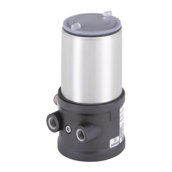
Type 8695 REV.3 System description SYSTEM DESCRIPTION The control head Type 8695 has been optimized for the integrated modular fitting of series 21xx process valves (ELEMENT) with Structure and function actuator size ∅ 50. Various expansion stages are possible thanks to the modular design. The control head Type 8695 can control single or double-acting process valves. For installation on the 20xx series (CLASSIC) there is a special variant. View without transparent cap, series 21xx (ELEMENT): Control head Pressure limiting valve (for pro- tection against too high internal Actuator pressure in case of error) Electrical connection... -
Page 8: Technical Data
Type 8695 REV.3 Technical data TECHNICAL DATA Operating conditions Standards and directives WARNING! The device complies with the relevant EU harmonisation legis- Solar radiation and temperature fluctuations may cause mal- lation. In addition, the device also complies with the require- functions or leaks. ments of the laws of the United Kingdom. ▶ If the device is used outdoors, do not expose it unprotected The harmonised standards that have been applied for the con- to the weather conditions. formity assessment procedure are listed in the current version of ▶ Ensure that the permitted ambient temperature does not the EU Declaration of Conformity/UK Declaration of Conformity. exceed the maximum value or drop below the minimum value. Approvals Ambient temperature see type label The product is approved for use in zone 2 and 22 in accordance Degree of protection with ATEX directive 2014/34/EU category 3GD. -
Page 9: Mechanical Data
Type 8695 REV.3 Technical data Mechanical data 6.5.2 UL type label Dimensions See data sheet Type, Features of the type code applicable to UL and ATEX Body material e xterior PPS, PC, stainless steel Control function, pilot valve, interior PA6, ABS supply voltage pilot valve 8695 -E1-...-0 PU02 Sealing material exterior EPDM/FKM Single act Pilot 0.6 24V Max. operating pressure Pmax 7 bar Stroke range of valve spindle Tamb -10 - +55 °C REV.3 Ambient temperature, version S/N 1001 2 1xx series (ELEMENT) Serial number, CE marking 00123456 W15MA and 20xx series (CLASSIC) 2 – 35 mm T hird-party devices Barcode... -
Page 10: Pneumatic Data
Type 8695 REV.3 Technical data Pneumatic data Electrical data Control medium n eutral gases, air WARNING! Quality classes in accordance with ISO 8573-1 Only circuits with limited power may be used for UL approved components according to “NEC Class 2”. Dust content C lass 7 max. particle size 40 µm, max. particle density 10 mg/m³ 6.7.1 Electrical data without field bus communication Water content Class 3 m ax. pressure dew point -20 °C or min. 10 °C below the Protection class III as per DIN EN 61140 (VDE 0140-1) lowest operating temperature Connections Oil content Class X max. 25 mg/m³... - Page 11 Type 8695 REV.3 Technical data Power consumption Communication incl. load on one software Bürkert Communicator active digital output 2 W / 5 W Actuator supply is galvanically isolated from system supply in accor- Communication dance with IEC 60664 and for electrical safety in accordance with software Bürkert Communicator SELV from IEC 61010-2-201 6.7.2 Electrical data, IO-Link 6.7.3 Electrical data, büS Protection class...
-
Page 12: Communication
Type 8695 REV.3 Installation INSTALLATION Current consumption m ax. 110 mA, only with installed pilot valve Only for control head without pre-assembled process Communication valve. software Bürkert Communicator Safety instructions Communication DANGER! 6.8.1 IO-Link Risk of injury from high pressure in the equipment/device. Port class ▶ Before working on equipment or device, switch off the pressure IO-Link Specification V1.1.2 and deaerate/drain lines. Supply via IO-Link (M12 x 1, 5-pin, A-coded) Risk of electric shock. ▶... -
Page 13: Installation Of The Control Head On Process Valves Of Series 21Xx
Type 8695 REV.3 Installation Installation of the control head on → Push the control head, without turning it, onto the actuator until no gap is visible on the form seal. process valves of series 21xx ATTENTION! ATTENTION! When mounting on process valves with a welded connection, Too high torque when screwing in the fastening screw does follow the installation instructions in the operating instructions not ensure protection class IP65 / IP67. -
Page 14: Installation Of The Control Head On Process Valves Of Series 20Xx
Type 8695 REV.3 Installation Installation of the control head on Ensure that the pneumatic connections of the control process valves of series 20xx head and those of the valve actuator are situated pref- erably vertically one above the other (see “Fig. 9”). Procedure: Guide rail ATTENTION! Too high torque when screwing in the fastening screw does not ensure protection class IP65 / IP67. ▶ The fastening screws may be tightened to a maximum torque of 1.5 Nm only. - Page 15 Type 8695 REV.3 Installation → Screw the plug-in hose connectors onto the control head and Control function A (CFA) the actuator. Process valve closed in rest position (by spring force) → Using the hoses supplied in the accessory kit, make the Pilot air outlet pneumatic connection between the control head and actuator with the “Tab. 1: Pneumatic connection to actuator”. Upper pilot air port ATTENTION! Lower pilot air port Damage or malfunction due to ingress of dirt and moisture. ▶ To comply with protection class IP65 / IP67, connect the Control function B (CFB) pilot air outlet (only for CFA or CFB) which is not required to Process valve open in rest position (by spring force) the free pilot air port of the actuator or seal with a plug. Pilot air outlet “In rest position” means that the pilot valves of the control head Type 8695 are isolated or not actuated.
-
Page 16: Manual Actuation Of The Actuator Via Pilot Valve
Type 8695 REV.3 Installation Manual actuation of the actuator via ATTENTION! pilot valve The manual override may be damaged if it is simultaneously The actuator can be moved without a power supply from the rest pressed and turned. position to its end position and back again, when the control air is ▶ Do not press the manual override when turning it. connected. To do this, the pilot valve must be actuated with a screwdriver. Pilot valve non activated (normal position) ATTENTION! Manual... -
Page 17: Pneumatic Installation
Type 8695 REV.3 Pneumatic installation PNEUMATIC INSTALLATION Important information for the problem-free functioning of the device: DANGER! ▶ The installation must not cause back pressure to build Risk of injury from high pressure in the equipment/device. ▶ Select a hose for the connection with an adequate ▶ Before working on equipment or device, switch off the pressure cross-section. and deaerate/drain lines. ▶ The exhaust air line must be designed in such a way that no water or other liquid can get into the device through WARNING! the exhaust air port. Risk of injury from improper installation. ▶ Installation may be carried out by authorized technicians only and with the appropriate tools. -
Page 18: Electrical Installation
Type 8695 REV.3 Electrical installation ELECTRICAL INSTALLATION Electrical installation, without fieldbus communication Safety instructions → Connect the control head according to the table. DANGER! Risk of electric shock. ▶ Before working on equipment or device, switch off the power supply and secure to prevent reactivation. ▶ Observe applicable accident prevention and safety regulations for electrical equipment. WARNING! Fig. 13: Circular plug M12 x 1, 8-pin Risk of injury from improper installation. Pin Wire color Designation Configuration... -
Page 19: Electrical Installation, Io-Link, Port Class B And Port Class A
Type 8695 REV.3 Electrical installation Electrical installation, IO-Link, Electrical installation, büS port class B and port class A Port class B Pin Desi- Configuration gnation 1 L + 24 V DC System supply 2 P24 24 V DC Actuator supply 3 L – 0 V (GND) System supply 4 C/Q IO-Link Fig. 14: Pin assignment 5 M24 0 V (GND) Actuator supply Tab. -
Page 20: Electrical Installation, As-Interface
Type 8695 REV.3 Electrical installation Electrical installation, AS-Interface 9.5.1 Connection with with circular plug-in connector Bus - Screws Bus + M12 plug-in connector branch circuit Fig. 16: Control head 8695 with multi-pole cable and ribbon cable Fig. 15: Pin assignment terminal Designation Configuration Handling the ribbon cable terminal The multi-pole cable features a ribbon cable terminal - with M12 Bus + AS-Interface bus line +... -
Page 21: Start-Up
Type 8695 REV.3 Start-up START-UP Actuator with stroke movement of the switch spindle 10.1 Invert process valve direction In the factory settings, the following actuator end positions and colours of the status indicator are assigned to the valve positions: Valve position Status indicator Actuator position Valve opens when pressurized Valve closes when pressurized Valve open is lit green Actuator deactivated below at the top Valve closed... - Page 22 Type 8695 REV.3 Start-up Invert process valve direction: process valve direction Transparent cap inversion Body casing enabled Basic housing disabled 10 s 30 s Inv.ValveDir. LED Actuator Fig. 19: Invert process valve direction Fig. 17: Open and close the device ATTENTION! → Keep key 2 pressed for > 10 s. The green Inv.ValveDir. LED Breakage of the pneumatic connection pieces due to rota- flashes for 10 s at 10 Hz.
-
Page 23: Teach Function: Determine End Positions And Save These, Rev.3
Type 8695 REV.3 Start-up 10.2 Teach function: Determine end 10.2.1 Start automatic teach function positions and save these, REV.3 For devices with pilot valve: The teach function automatically identifies and saves the end • Automatic teach function: For devices with pilot valve positions of the valve. The teach function automatically identifies and saves the end positions of the valve. Essential requirements: • Manual teach function: For devices without pilot valve • The device is mounted on the actuator. The end positions are captured and saved automatically. • The supply voltage is connected. • Teach-in-operation function: The teach-in operation function •... - Page 24 Type 8695 REV.3 Start-up → Open the device: turning the transparent cap anti-clockwise. → When the red manual LED and the green Inv.ValveDir. LED start flashing faster (10 Hz), release key 1 within the next 5 s. Key 1 T he status indicator flashes orange while the automatic teach ASi PWR LED function is running (function check). When the status indicator Pilot LED (green) stops flashing orange, the teach function is complete. Inv.ValveDir. LED The end positions of the valve have been identified and saved. ASi FAULT LED Note: I f the status indicator is lit red, the teach function is faulty büS service (red) and must be repeated. interface ATTENTION! Manual LED Status indicator Damage or malfunction due to penetration of dirt and humidity. (RGB LED) Key 2 ▶...
- Page 25 Type 8695 REV.3 Start-up 10.2.2 Start manual teach function Key 1 For devices without pilot valve: ASi PWR LED The end positions are captured and saved manually by the user. Pilot LED (green) Essential requirements: Inv.ValveDir. LED • The device is mounted on the actuator. ASi FAULT LED büS service • The supply voltage is connected. (red) interface • The compressed air supply is connected. Manual LED • So that the correct reference conditions are identified, the pilot Status indicator pressure must correspond to the operating conditions. (RGB LED) Key 2 • Provide the possibility for the user to switch the pneumatic Fig. 24: Operating and display elements actuator (open and closed).
- Page 26 Type 8695 REV.3 Start-up 10.2.3 Teach-in-operation function T he status indicator flashes orange while the manual teach The teach-in-operation function can be used if the device is to carry function is running (function check). out the end positions of the process valve automatically during → Check whether the pneumatic actuator is in the deaerated, normal operation (once when the control unit is switched on for unactuated end position. the first time). → Confirm this end position by briefly pressing key 1. This function may only be used for process valve actuators with Yellow Pilot LED is lit. control function A (normally closed). → Move the pneumatic actuator into the aerated, switched end The function must first be enabled via the büS service interface position. (Bürkert Communicator). → Confirm this end position by briefly pressing key 1. For devices that are delivered without a process valve, this function Yellow Pilot LED is not lit. is already enabled because no other teach function has yet been carried out.
-
Page 27: Setting The Device With Bürkert Communicator
Type 8695 REV.3 Start-up Note: the enabling of this function is also reset if one of the other two Transparent cap teach functions (automatic or manual teach function) was carried out before the first switching. Body casing Basic housing 10.3 Setting the device with Bürkert Communicator Actuator The Bürkert Communicator can be used to make all settings on the device. Fig. 26: Open device The settings in the Bürkert Communicator can be found in ATTENTION the operating manual. Breakage of the pneumatic connection pieces due to rota- tional impact. 10.3.1 Connecting the device with Bürkert ▶... -
Page 28: 10.4 Io-Link
→ Implementing settings. protocol based on CANopen. 10.5.2 Configuration of the fieldbus büS device: The required start-up files and the description of objects are Required components: available on the Internet. • Communications software: Bürkert Communicator for PC Download from: • USB-büS interface set (see accessories) www.burkert.com / Type 8695 / Software → Establish connection to PC with USB-büS interface set. → Starting Bürkert Communicator. 10.6 AS-Interface → Implementing settings. 10.6.1 Certification The device is certified according to AS-Interface specification 10.4 IO-Link version 3.0. 10.4.1 Configuration of the fieldbus Certificate No.: on request... -
Page 29: Control And Display Elements
Type 8695 REV.3 Control and Display elements CONTROL AND DISPLAY ELEMENTS Description of the displays Status indicator RGB Valve position, error, warning Key 1 see chapter „Status indicator“ ASi PWR LED Pilot LED (green) Pilot LED yellow Is lit: pilot valve is actuated (on) Manual LED red Is lit: MANUAL operating state active Inv.ValveDir. LED Flashes at 10 Hz for 0–2 s: Switch ASi FAULT LED büS service MANUAL ↔ AUTO (red) interface Inv.ValveDir. green Is lit: inversion of process valve direction Manual LED active Status indicator Manual LED red and Both flash after pressing and holding key 1: (RGB LED) -
Page 30: Open And Close The Device
Type 8695 REV.3 Control and Display elements 11.1 Open and close the device 11.2 Operating state To operate the keys, make sure that the local control lock ATTENTION! is deactivated/unlocked (factory setting): with communi- Breakage of the pneumatic connection pieces due to rota- cation software or fieldbus communication. tional impact. ▶ When unscrewing and screwing in the transparent cap, do not AUTOMATIC (AUTO) hold the actuator of the process valve but the basic housing. In AUTOMATIC operating state, the device is in normal operation: the valve is controlled via the process interface. → Unscrew the transparent cap in a counter-clockwise direction. MANUAL (MANU) Transparent cap In MANUAL operating state the valve can be opened and closed... - Page 31 Type 8695 REV.3 Control and Display elements Changing the operating state (MANU ↔ AUTO) Switch pilot valve (only possible in MANUAL operating state) Pilot valve Oparating state MANU Operating state MANU AUTO 10 s Status indicator Status indicator Manual LED Manual LED Pilot LED Fig. 31: Switch pilot valve Fig.
- Page 32 Type 8695 REV.3 Control and Display elements Perform device restart Factory reset 10 s 30 s 10 s 30 s Inv.ValveDir. LED Device restart Factory reset Inv.ValveDir. LED Manual LED Manual LED Pilot LED Pilot LED Fig. 32: Perform device restart Fig. 33: Factory reset → Keep keys 1 and 2 pressed for 10–30 s. The red manual LED →...
- Page 33 Type 8695 REV.3 Control and Display elements 11.3.1 Status indicator The description for setting the LED mode can be found in the section "Setting the LED mode, status indicator" in Key 1 the operating instruction. ASi PWR LED Pilot LED (green) Displays in valve mode + warnings (factory setting) Inv.ValveDir. LED • Valve position: open, half-way, closed ASi FAULT LED büS service • Device status: failure, function check, out of specification, (red) interface maintenance required (according to NAMUR) Manual LED If several device statuses exist simultaneously, the device status Status indicator with the highest priority is displayed. (RGB LED) Key 2 Fig.
- Page 34 Type 8695 REV.3 Control and Display elements Valve position Device status Valve position Device status Status, Error Status, Maintenance required colour colour Open is lit yellow* blinks red alternately with yellow* Open is lit yellow* blinks blue alternately with yellow* Half-way LED off* blinks red alternately with LED off* Half-way LED off* blinks blue alternately with LED off* Closed is lit green* blinks red alternately with green* Closed...
-
Page 35: Safety End Positions
Type 8695 REV.3 Safety end positions SAFETY END POSITIONS Status display in accordance with NE 107, edition 2006-06-12 Color Color Status Description Safety end positions code after failure of the aux- Actuator Outage, error Normal operation is not pos- Designation iliary power system or malfunction sible due to a malfunction in electrical pneumatic the device or on its peripheral... -
Page 36: Accessories
Type 8695 REV.3 Accessories ACCESSORIES If you have any questions regarding compatibility, please contact the Bürkert Sales Center. Designation Order no. A detailed description and precise schedule of the pro- cedure for the installation and operation of the software Connection cable M12 x 1, 8-pin 919061 can be found in the associated documentation. Wrench for opening/closing the trans- Download the software at: www.burkert.com 674078 parent cap PACKAGING, TRANSPORT, Communication software Bürkert Information at STORAGE Communicator www.burkert.com ATTENTION! USB-büS interface set: Transport damages. USB-büS interface set (büS stick + 0.7 m 772551 Inadequately protected equipment may be damaged during cable with M12 plug) transport. - Page 38 www.burkert.com...
Need help?
Do you have a question about the 8695 Series and is the answer not in the manual?
Questions and answers