Burkert 8691 Operating Instructions Manual
Control head rev.2
Hide thumbs
Also See for 8691:
- Operating instructions manual (190 pages) ,
- Quick start manual (82 pages) ,
- Operating instructions manual (66 pages)

Related Manuals for Burkert 8691


Summary of Contents for Burkert 8691
- Page 1 Type 8691 Rev.2 Control Head Steuerkopf Tête de commande Operating Instructions Bedienungsanleitung Manuel d‘utilisation...
- Page 2 We reserve the right to make technical changes without notice. Technische Änderungen vorbehalten. Sous réserve de modifications techniques. © Bürkert Werke GmbH & Co. KG, 2017 Operating Instructions 1707/00_EU-ML_00810626 / Original DE...
-
Page 3: Table Of Contents
Type 8691, Rev. 2 Control head Type 8691, Rev. 2 able of conTenTs ABOUT THESE INSTRUCTIONS ......................8 Symbols ............................8 1.2 Definition of terms ........................8 INTENDED USE ............................9 BASIC SAFETY INSTRUCTIONS ......................10 GENERAL INFORMATION ........................11 Contact address .........................11 Warranty .............................11 4.3 Information on the Internet ......................11 Trademarks ..........................11... - Page 4 Type 8691, Rev. 2 Inhaltsverzeichnis 6.5 Operating conditions .........................16 6.5.1 Fluidic data .........................16 6.5.2 Electrical data ......................16 6.5.2.1 Electrical data, IO-Link ..................16 6.5.2.2 Electrical data, büS....................17 6.6 Mechanical data .........................17 6.6.1 Safety end positions ....................17 MECHANICAL INSTALLATION ......................18 7.1 Safety instructions ........................18 7.2 Installing devices with integrated pilot air duct (21xx, Element) ..........18...
- Page 5 Type 8691, Rev. 2 10.3 IO-Link ............................38 10.3.1 Information, IO-Link ....................38 10.3.2 Technical specifications, IO-Link ................38 10.3.3 Interfaces, IO-Link ......................39 10.3.4 Process data, IO-Link ....................39 10.3.4.1 Process input data (PDin) ..................39 10.3.4.2 Process output data (PDout) ..................40 10.3.5 Non-cyclic parameters (On-Request Data (ISDU)) .............40 10.3.5.1 0x2000 Buerkert Device Description Object ............41...
- Page 6 Type 8691, Rev. 2 10.4.3.13 0x2420 No Measure Values ...................59 10.4.3.14 0x2421 No Control Values ..................59 10.4.3.15 0x2422 No Calibration Values ................59 10.4.3.16 0x2426 MPDO Inhibit Time bueS ................59 10.4.3.17 0x242C Partner Status Object ................59 10.4.3.18 0x2500 GMV Position ....................60 10.4.3.19 0x2501 GMV End Positions ...................60...
- Page 7 Type 8691, Rev. 2 SPARE PARTS, ACCESSORIES ......................78 14.1 Communications software ......................78 TRANSPORTATION, STORAGE, DISPOSAL ..................79 english...
-
Page 8: About These Instructions
▶ Designates an instruction for risk prevention. → Designates a procedure which you must carry out. Indicates a result. Definition of terms In these instructions the term “device” denotes the following device types: Control head Type 8691 Rev. 2. english... -
Page 9: Intended Use
Type 8691, Rev. 2 Intended use INTENDED USE The control head Type 8691 Version 2 is designed to be mounted on pneumatic actuators of process valves for the control of media. The permitted fluid media are listed in the technical data. ▶ Use the device for its intended purpose only. Non-intended use of the device may be dangerous to people, nearby equipment and the environment. ▶ Correct transportation, correct storage as well as correct installation, commissioning, operation and maintenance are essential for reliable and problem-free operation. -
Page 10: Basic Safety Instructions
Type 8691, Rev. 2 Basic safety instructions BASIC SAFETY INSTRUCTIONS These safety instructions do not consider any contingencies or incidents which occur during installation, operation and maintenance. The operator is responsible for observing the location-specific safety regulations, also with reference to the personnel. DANGER Risk of injury from high pressure and discharge of medium. ▶ Before working on the device or system, switch off the pressure. Vent or drain lines. DANGER Risk of injury from electric shock. ▶ Before working on the device or system, switch off the power supply. Secure against reactivation. ▶ Observe applicable accident prevention and safety regulations for electrical equipment. -
Page 11: General Information
Type 8691, Rev. 2 General information GENERAL INFORMATION Contact address Germany Bürkert Fluid Control System Sales Center Chr.-Bürkert-Str. 13-17 D-74653 Ingelfingen Tel. + 49 (0) 7940 - 10 91 111 Fax + 49 (0) 7940 - 10 91 448 E-mail: info@burkert.com International Contact addresses can be found on the final pages of the printed operating instructions. -
Page 12: Product Description
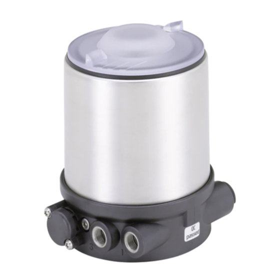
Type 8691, Rev. 2 Product description PRODUCT DESCRIPTION Structure The modular design of the device supports various configurations and variants. View without transparent cap: Display device status: high-power LEDs Pilot valve LED Status LED Pilot air port, label: 1 Exhaust air port, label: 3 Fastening screw Pressure limiting valve Electrical connection:... -
Page 13: Variants
Type 8691, Rev. 2 Product description 5.1.3 Variants Communication possible via: • IO-Link • büS Function This device is capable of controlling single-acting and double-acting process valves. The pilot valves can be manually overridden. An analog, inductive sensor element provides feedback about end positions being reached. The teach function is used for configuration. -
Page 14: Technical Data
Type 8691, Rev. 2 Technical data TECHNICAL DATA Conformity The device conforms to the EC directives as per the EC Declaration of Conformity (if applicable). Standards The applied standards, which are used to demonstrate conformity with the EC Directives, are listed in the EC type examination certificate and/or the EC Declaration of Conformity (if applicable). -
Page 15: Type Label
Type 8691, Rev. 2 Technical data Type label 6.4.1 Type label standard Operating voltage or fieldbus control Type Control function, pilot valve 8691 büS Max. operating pressure single act pilot 3,0 Pmax 7bar Ambient temperature, version Tamb -10 - +55°C Rev. 2 Ser.-Nr. 001000... -
Page 16: Operating Conditions
Type 8691, Rev. 2 Technical data Operating conditions Ambient temperature See type label Degree of protection Evaluated by manufacturer: IP65, IP67 as per EN 60529* Evaluated by UL: UL type 4x Rating* 6.5.1 Fluidic data Control medium Neutral gases, air... -
Page 17: Electrical Data, Büs
Type 8691, Rev. 2 Technical data 6.5.2.2 Electrical data, büS Protection class 3 as per DIN EN 61140 (VDE 0140-1) Connection Circular plug-in connector M12 x 1, 5-pin Operating voltage 18–30 V DC (according to specification) Max. current consumption 120 mA @18 V (incl. inrush current pilot valve for 200 ms) Current consumption input during 95 mA @18 V normal operation (after current reduction, pilot valve after 200 ms and 1 end position reached) -
Page 18: Mechanical Installation
Type 8691, Rev. 2 Mechanical installation MECHANICAL INSTALLATION Safety instructions DANGER Risk of injury from high pressure and discharge of medium. ▶ Before working on the device or system, switch off the pressure. Vent or drain lines. WARNING Risk of injury from improper installation. ▶ Only trained technicians may perform installations. ▶ Perform installations with suitable tools only. WARNING Risk of injury due to unintentional activation and uncontrolled start-up of the system. ▶ Secure system against unintentional activation. ▶ Ensure that the system does not start up in an uncontrolled manner. - Page 19 Type 8691, Rev. 2 Mechanical installation 1. Installing the switch spindle Transparent cap Position indicator Pilot air ports (plug-in connectors with collets or threaded bushings) Actuator Figure 7: Installing the switch spindle (1), integrated pilot air duct → Unscrew the transparent cap from the actuator.
- Page 20 Type 8691, Rev. 2 Mechanical installation 2. Attaching the form seal → Pull the form seal onto the actuator cover (smaller diameter points upwards). → Check that the O-rings are correctly positioned in the pilot air ports. Before installing the device, remove the collets in the pilot air ports.
-
Page 21: Installing Devices With External Control Air Duct (20Xx, Classic)
Type 8691, Rev. 2 Mechanical installation Connection piece 2x fastening screw Pilot air ports (max. 1.5 Nm) Figure 11: Installation Installing devices with external control air duct (20xx, Classic) Only for devices without preinstalled process valve. Required attachment kit: Classic Type 20xx for the corresponding variant NOTE Damage to the device and the drive when welding welded bodies. - Page 22 Type 8691, Rev. 2 Mechanical installation Puck Switch spindle Guide element Max. 8 Nm O-ring Max. 1 Nm Actuator cover Plastic part Spindle (actuator) Figure 13: Installing the switch spindle (2), external pilot air duct → Press O-ring down into the actuator cover.
- Page 23 Type 8691, Rev. 2 Mechanical installation Guide rail Puck Figure 15: Aligning the puck → Press the device all the way down to the actuator and turn it into the required position. Ensure that the pneumatic connections of the device and those of the valve actuator are situated preferably vertically one above the other (see Fig. below). For different positioning, longer hoses may...
- Page 24 Type 8691, Rev. 2 Mechanical installation Control function A (CFA) Process valve closed in resting position (by spring force) Device Pilot air outlet Actuator Upper pilot air port Lower pilot air port Control function B (CFB) Process valve open in resting position (by spring force)
-
Page 25: Aligning (Turning) The Device And Position Of Connections
Type 8691, Rev. 2 Mechanical installation Aligning (turning) the device and position of connections Devices with integrated pilot air duct: Alignment of device and position of connections is only possible with 2100, 2101 and 2106 process valves. The device and position of the connections can be aligned by: - turning the actuator Devices with external pilot air duct: The device and position of the connections can be aligned by:... - Page 26 Type 8691, Rev. 2 Mechanical installation With 3-position actuator: NOTE Damage to the seat seal or the seat contour. ▶ When turning the actuator, the valve must be in the central position. → Apply compressed air to pilot air port 1: 3.5 bar for actuator size 50 (D) and 70 (M) 4.0 bar for actuator size 90 (N) and 130 (P)
-
Page 27: Turning The Actuator, Devices Without Hexnut
Type 8691, Rev. 2 Mechanical installation 7.4.2 Turning the actuator, devices without hexnut The position of the connections can be infinitely adjusted by rotating the actuator through 360°. Actuator Key-fit forms Wrench flat on the body connection Figure 19: Turning the actuator (1), devices without hexnut → Clamp the valve body into a holding device (only for valves not yet installed). - Page 28 Type 8691, Rev. 2 Mechanical installation DANGER Risk of injury from high pressure and discharge of medium. If the direction of rotation is wrong, the body connection may become detached. ▶ Only turn the actuator is the prescribed direction. → By rotating in a clockwise direction (viewed from below), move the actuator to the desired position.
-
Page 29: Turning The Device
Type 8691, Rev. 2 Mechanical installation 7.4.3 Turning the device Only for devices with external pilot air duct (20xx, Classic). The position of the connections can be aligned by rotating the device continuously through 360°. Device Fastening screw (2x) Pneumatic connection Actuator Figure 21: Turning the device → Loosen pneumatic connection between device and actuator. -
Page 30: Pneumatic Installation
Type 8691, Rev. 2 Pneumatic installation PNEUMATIC INSTALLATION Safety instructions DANGER Risk of injury from high pressure and discharge of medium. ▶ Before working on the device or system, switch off the pressure. Vent or drain lines. WARNING Risk of injury from improper installation. ▶ Only trained technicians may perform installations. ▶ Perform installations with suitable tools only. WARNING Risk of injury due to unintentional activation and uncontrolled start-up of the system. ▶ Secure system against unintentional activation. ▶ Ensure that the system does not start up in an uncontrolled manner. -
Page 31: Electrical Installation
Type 8691, Rev. 2 Electrical installation ELECTRICAL INSTALLATION Safety instructions for electrical installation DANGER Risk of injury from electric shock. ▶ Before working on the device or system, switch off the power supply. Secure against reactivation. ▶ Observe applicable accident prevention and safety regulations for electrical equipment. WARNING Risk of injury from improper installation. ▶ Only trained technicians may perform installations. ▶ Perform installations with suitable tools only. -
Page 32: Connecting The Device Electrically, Büs
Type 8691, Rev. 2 Electrical installation Connecting the device electrically, büS Figure 24: Pin assignment Wire color Assignment CAN plate/shielding CAN plate/shielding +24 V DC ± 10%, max. residual ripple 10% black GND / CAN_GND white CAN_H blue CAN_L Table 5: Pin assignment For electrical installation with büS network, note:... -
Page 33: Start-Up
Type 8691, Rev. 2 Start-up START-UP 10.1 Teach function: Determine end positions and save these, Rev. 2 • Automatic teach function: For devices with pilot valve The teach function automatically identifies and saves the end positions of the valve. • Manual teach function: For devices without pilot valve The end positions are captured and saved automatically. - Page 34 Type 8691, Rev. 2 Start-up Pilot valve LED (V) Status LED (red) Status LED (green) Button to start the teach function Figure 26: Starting teach function → Hold down the button to start the teach function for approx. 5 s until the red status LED blinks.
-
Page 35: Manual Teach Function
Type 8691, Rev. 2 Start-up 10.1.2 Manual teach function For devices without pilot valve: The end positions are captured and saved manually by the user. With the IO-Link variant, the teach function can also be started with an acyclic IO-Link parameter (see parameter list) or with the Bürkert Communicator. - Page 36 Type 8691, Rev. 2 Start-up → Hold down the button to start the teach function for at least 10 s. After 5 s, the red status LED will start blinking. Keep the button pressed down. After a further 5 s, the red LED blinks very quickly.
-
Page 37: Setting With Bürkert Communicator
Type 8691, Rev. 2 Start-up 10.2 Setting with Bürkert Communicator The Bürkert Communicator can be used to make all settings on the device. The settings in the Bürkert Communicator can be found in the operating manual. 10.2.1 Connecting IO-Link device with Bürkert Communicator Required components: •... -
Page 38: Connecting Büs Device With Bürkert Communicator
Type 8691, Rev. 2 Start-up 10.2.2 Connecting büS device with Bürkert Communicator Required components: • Communications software: Bürkert Communicator for PC • büS standard set (see accessories) → Establish connection to PC with büS stick. → Starting Bürkert Communicator. →... -
Page 39: Interfaces, Io-Link
Type 8691, Rev. 2 Start-up 10.3.3 Interfaces, IO-Link Control head büS service Supply interface IO-Link, SIO mode 8691 IO-Link Figure 31: Interfaces büS service interface (micro USB plug) Figure 32: büS service interface 10.3.4 Process data, IO-Link 10.3.4.1 Process input data (PDin) -
Page 40: Process Output Data (Pdout)
Type 8691, Rev. 2 Start-up 10.3.4.2 Process output data (PDout) Length: 1 bytes Sub- Length Data type Description index offset (bits) Boolean CMD set-point value True = Open False = Closed Boolean Locating function (fast flashing LEDs) True = Activated False = Deactivated Table 7: Process output data 10.3.5... -
Page 41: 0X2000 Buerkert Device Description Object
Type 8691, Rev. 2 Start-up 10.3.5.1 0x2000 Buerkert Device Description Object Sub- Name Description Factory index reset Device Name Unique device name STRING Used to identify the device Ident Number Device identification number UINT32 Manufacture Date Manufacture date STRING Software Ident Identification number of firmware... -
Page 42: 0X2101 Locating Function
Type 8691, Rev. 2 Start-up 10.3.5.3 0x2101 Locating function Sub- Name Description Factory index reset Locating function Activate or deactivate locating function: UINT8 This function enables a device in the system to be located using the PLC. The top LED indicator will briefly start to flash when the locating function is activated... -
Page 43: 0X2122 External Color
Type 8691, Rev. 2 Start-up 10.3.5.5 0x2122 External color Sub- Name Description Factory index reset Color for external Select external LED color UINT32 color mode Byte 0: Red component Byte 1: Green component Byte 2: Blue component Byte 3: Bit 0-3: 0=Always on; 1=Slow flashing; 2=Fast flashing;... -
Page 44: 0X2C01 Led Color For End Positions
Type 8691, Rev. 2 Start-up 10.3.5.6 0x2C01 LED color for end positions Sub- Name Description Factory index reset Color valve opened LED color for valve open: UINT8 Select top LED color for valve in open position 0: Off 1: White 2: Green... - Page 45 Type 8691, Rev. 2 Start-up Sub- Name Description Factory index reset Lower tolerance band Tolerance band for the lower end position FLOAT32 (closed) in mm Inverting CMD Invert CMD set-point value UINT8 setpoint 0 = CMD set-point value inversion inactive...
-
Page 46: 0X2C0C Teach Function
Type 8691, Rev. 2 Start-up 10.3.5.8 0x2C0C Teach function Sub- Name Description Factory index reset Upper end position Upper end position in mm FLOAT32 Lower end position in mm Lower end position FLOAT32 Opening time Opening time: UINT16 Time, measured from the time when... -
Page 47: 0X2C0D Cmd Set-Point
Type 8691, Rev. 2 Start-up Sub- Name Description Factory index reset Teach function start Start teach function: UINT8 Function for measuring the stroke, opening time, closing time and end positions. 0: Finished (teach function aborted) 1: Start automatic teach function... -
Page 48: 0X2C0E Diagnostics
Type 8691, Rev. 2 Start-up 10.3.5.10 0x2C0E Diagnostics Sub- Name Description Factory index reset Travel accumulator Travel accumulator total: FLOAT32 Travel distance of the valve spindle from factory default is added up to determine the service life. Travel accumulator resettable:... - Page 49 Type 8691, Rev. 2 Start-up Sub- Name Description Factory index reset Reset command Reset counters: UINT8 The resettable counters can be reset as follows: Bit0 = 1: Reset switching cycles Bit1 = 1: Reset travel accumulator Bit2 = 1: Reset operating time counters...
- Page 50 Type 8691, Rev. 2 Start-up Sub- Name Description Factory index reset 0x10 Pilot valve cycles Number of pilot valve switching cycles UINT32 0x11 Active warnings Active warnings (bit field) UINT16 Bit0: Travel accumulator threshold reached Bit1: Valve switching cycle threshold reached Bit2: Operating time threshold reached...
-
Page 51: 0X2C0F Io-Link Sio Mode Settings
Type 8691, Rev. 2 Start-up 10.3.5.11 0x2C0F IO-Link SIO mode settings Sub- Name Description Factory index reset SIO mode Select SIO mode: UINT8 0: Pin 4 (output) Low = Valve not closed; High =Valve closed Pin 2 (output) Low = Valve not open;... -
Page 52: Io-Link-Events
Type 8691, Rev. 2 Start-up 10.3.5.12 IO-Link-Events Message Description IO-Link IO-Link Action event code event type Internal error Internal device error 0x1000 ERROR Contact Bürkert Service Internal error: WMS Data from WMS 0x1800 ERROR Restart device signal error defective If fault persists, contact Bürkert Service... - Page 53 Type 8691, Rev. 2 Start-up Message Description IO-Link Action IO-Link event code event type Temperature error Device temperature for 0x4000 ERROR Modify ambient temperature. overload operation too high or too If fault persists, contact Bürkert Service Temperature Ambient temperature too...
-
Page 54: Büs
Type 8691, Rev. 2 Start-up 10.4 büS 10.4.1 Information, büS büS is a system bus developed by Bürkert with a communication protocol based on CANopen. 10.4.2 Interfaces, büS Control head Supply büS 8691 büS Figure 33: Interfaces 10.4.3 Objects 10.4.3.1... -
Page 55: 0X2001 Device Communication Object
Type 8691, Rev. 2 Start-up 10.4.3.2 0x2001 Device Communication Object Sub- Name Description Factory index reset Baud rate Specified by CANopen (see chapter on baud rates for more details) Address Device address range 0...127 handled automatically in büS mode büS mode Select büS mode 0: CANopen For CANopen applications 1: büS mode F or CANopen, supplemented with specific... -
Page 56: 0X2002 User Configuration Object
Type 8691, Rev. 2 Start-up 10.4.3.3 0x2002 User Configuration Object Sub- Name Description Factory index reset Unique Device Name Imported by Bürkert Device Description Object during device startup Location Information Additional user information about device location User Description Additional user-defined information about the device Displayed Device... -
Page 57: 0X2100 Get Mapping Function
Type 8691, Rev. 2 Start-up Bit 7 Bit 6 Bit 5 Bit 4 Bit 3 Bit 2 Bit 1 Bit 0 Gateway: F(x): NAMUR mode: NAMUR state 0 - Run 0 - Run 0 - Automatic 0 - Normal 1 - Stop 1 - Stop 1 - Manual... -
Page 58: 0X2120 Led Mode
Type 8691, Rev. 2 Start-up 10.4.3.8 0x2120 LED mode Sub- Name Description Factory index reset LED modes Select LED indicator mode Please refer to the chapter “Device status indicator” of the operating instructions for a description of the possible indicator modes... -
Page 59: 0X2200 Buerkert Driver Archive
Type 8691, Rev. 2 Start-up 10.4.3.10 0x2200 Buerkert Driver Archive Internal object 10.4.3.11 0x2220 EDS Internal object 10.4.3.12 0x2400 Sensor Type Internal object 10.4.3.13 0x2420 No Measure Values Internal object 10.4.3.14 0x2421 No Control Values Internal object 10.4.3.15 0x2422 No Calibration Values Internal object 10.4.3.16 0x2426 MPDO Inhibit Time bueS... -
Page 60: 0X2500 Gmv Position
Type 8691, Rev. 2 Start-up 10.4.3.18 0x2500 GMV Position Sub- Name Description Factory index reset Value Current valve position in % Unit 0xFE000000 Name GMV position Object name Classification 0x000E büS-specific Data type 0x08 REAL32 Precision 0.1 büS-specific Feature group 0 b üS-specific... -
Page 61: 0X2540 Gcv Setpoint
Type 8691, Rev. 2 Start-up 10.4.3.20 0x2540 GCV Setpoint Sub- Name Description Factory index reset Value CMD set-point value Bit0: Closed Bit1: Open Unit Name GCV.Setpoint Object name Classification 0x001C büS-specific Data type 0x05 UINT8 Precision 1 büS-specific Feature group 0 b üS-specific... -
Page 62: 0X2C0B Xcontrol
Type 8691, Rev. 2 Start-up Sub- Name Description Factory index reset LED_ColorBetween LED color for valve in-between: Select top LED color for valve position between closed and open 0: Off 1: White 2: Green 3: Blue 4: Yellow 5: Orange 6: Red... -
Page 63: 0X2C0C Teach Function
Type 8691, Rev. 2 Start-up Sub- Name Description Factory index reset ValveMode Valve mode 0 = Initialization 1 = AUTOMATC operating state 2 = Teach function active 3 = SafePos active Device lock Activate or deactivate local operation: Button for manual operation inside the device is deacti-... - Page 64 Type 8691, Rev. 2 Start-up Sub- Name Description Factory index reset Indicates whether teach function has been successfully IsCalibrated completed 0: Device has not been taught 1: Device has been taught TuneState State of teach function: Displays the sequence of the phases 0–5 of the teach...
-
Page 65: 0X2C0D Cmd Set-Point
Type 8691, Rev. 2 Start-up 10.4.3.24 0x2C0D CMD set-point Sub- Name Description Factory index reset Select CMD set-point value source: CMD set-point value source Configure the source of the control signal for opening and closing the valve 0: büS/CanOpen 1: IO-Link 2: Internal button (manual) 3: Manual set-point value (see 0x4) - Page 66 Type 8691, Rev. 2 Start-up Sub- Name Description Factory index reset Switching cycles: Activate or deactivate maintenance Totalizer Valve Cycles Service Limit threshold 0: Diagnostics deactivated >0: Diagnostics activated Warning is output when the number of resettable switching cycles reaches this threshold...
- Page 67 Type 8691, Rev. 2 Start-up Sub- Name Description Factory index reset Number of times opening time threshold exceeded OpeningErrorCnt (resettable): Value configured in “opening time limit” + “time tolerance” has been exceeded ClosingErrorCnt Number of times closing time threshold exceeded (resettable): Value configured in “closing time limit” + “time tolerance” has been exceeded TuneStarts Number of teach functions performed...
-
Page 68: 0X2C0F Io-Link Sio Mode Settings
Type 8691, Rev. 2 Start-up 10.4.3.26 0x2C0F IO-Link SIO mode settings Internal object 10.4.3.27 0x2C11 MenuOptionBits Internal object 10.4.3.28 0x2C13 FactoryReset Sub- Name Description Factory index reset Factory reset parameters 0: Complete 111: Factory reset start Table 37: 0x2C13 FactoryReset 10.4.3.29 Baud rates... -
Page 69: Operation
Type 8691, Rev. 2 Operation OPERATION 11.1 Display device status, IO-Link and büS Following device statuses are indicated with LEDs: • Pilot valve LED: Activation of pilot valve • Device status LED: Valve position, errors, warnings • Status LED green: IO-Link mode •... -
Page 70: Pilot Valve Led
Type 8691, Rev. 2 Operation 11.1.1 Pilot valve LED Color Status Description yellow is lit Pilot valve is activated yellow is not lit Pilot valve is not activated Table 38: Pilot valve LED 11.1.2 Status LED, green and red Color... -
Page 71: Valve Mode
Type 8691, Rev. 2 Operation 11.1.3.1 Valve mode Displays in valve mode: • Valve position: open, half-way, closed Valve position Valve position status, color Open is lit yellow* Half-way LED off* Closed is lit green* Table 41: Valve mode 11.1.3.2 Valve mode + errors Displays in valve mode + errors: •... - Page 72 Type 8691, Rev. 2 Operation Valve position Valve position Device status: Function control status, color status, color Open is lit yellow* blinks alternately orange and yellow* Half-way is lit white* blinks alternately orange and white* Closed is lit green* blinks alternately orange and green*...
-
Page 73: Namur Mode
Type 8691, Rev. 2 Operation 11.1.3.4 NAMUR mode The device status LEDs (top LED) show the device status. The display elements change color in accordance with NAMUR NE 107. If several device statuses exist simultaneously, the device status with the highest priority is displayed. The priority is determined by the severity of the deviation from controlled operation (red LED = failure = highest priority). - Page 74 Type 8691, Rev. 2 Operation Switching the device: Manual override Pilot valve Basic housing Figure 37: Manually switching the device NOTE Damage to the manual override by pressing and rotating at the same time. ▶ Do not simultaneously press and turn manual override. Switching the positions for manual override: Lock function: 90° rotation = maintained-contact switching...
-
Page 75: Maintenance
Type 8691, Rev. 2 Maintenance MAINTENANCE 12.1 Servicing the air intake filter To protect the pilot valve and actuator, the pilot air is filtered. Air flows through the air intake filter from inside to outside through the filter fabric in its pre-installed state. DANGER! Risk of injury if not maintained correctly. ▶ Only trained and qualified personnel may perform maintenance. ▶ Perform maintenance with suitable tools only. Push-in connector O-ring Air intake filter Figure 40: Servicing the air intake filter DANGER! Risk of injury from high pressure and discharge of medium. ▶ Before working on the device or system, switch off the pressure. Vent or drain lines. -
Page 76: Deinstallation
Type 8691, Rev. 2 Deinstallation DEINSTALLATION 13.1 Safety instructions deinstallation DANGER Risk of injury from high pressure and discharge of medium. ▶ Before working on the device or system, switch off the pressure. Vent or drain lines. DANGER Risk of injury from electric shock. ▶ Before working on the device or system, switch off the power supply. Secure against reactivation. ▶ Observe applicable accident prevention and safety regulations for electrical equipment. WARNING Risk of injury due to improper deinstallation. ▶ Only trained technicians may perform deinstallations. ▶ Perform deinstallations with suitable tools only. -
Page 77: Deinstallation
Type 8691, Rev. 2 Deinstallation 13.2 Deinstallation Body casing Fastening screws Circular plug-in Basic housing connector Pneumatic connection Pilot air port Actuator External pilot air Exhaust air port duct (Classic) Integrated pilot air duct (Element) Figure 41: Deinstalling the device Pneumatically deinstalling the device →... -
Page 78: Spare Parts, Accessories
772407 Table 48: Accessories 14.1 Communications software The Bürkert Communicator PC program is designed for communication with Type 8691 devices with fieldbus control via DeviceNet, IO-Link or büS. Devices from year of construction April 2014 support the full range of functions. For questions regarding compatibility, please contact the Bürkert Sales Center. A detailed description for installing and operating the software can be found in the associated operating instructions. Download the software from: www.burkert.com... -
Page 79: Transportation, Storage, Disposal
Type 8691, Rev. 2 Transportation, storage, disposal TRANSPORTATION, STORAGE, DISPOSAL NOTE Damage in transit due to inadequately protected devices. ▶ Protect the device against moisture and dirt in shock-resistant packaging during transportation. ▶ Observe permitted storage temperature. NOTE Incorrect storage may damage the device. ▶ Store the device in a dry and dust-free location. - Page 80 Type 8691, Rev. 2 english...
- Page 82 www.burkert.com...
Need help?
Do you have a question about the 8691 and is the answer not in the manual?
Questions and answers