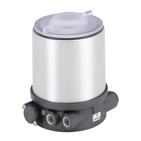
Burkert 8691 Quick Start Manual
Control head
Hide thumbs
Also See for 8691:
- Operating instructions manual (190 pages) ,
- Quick start manual (82 pages) ,
- Quick start manual (32 pages)

Subscribe to Our Youtube Channel
Related Manuals for Burkert 8691


Summary of Contents for Burkert 8691
- Page 1 Type 8691 Control Head Steuerkopf Tête de commande Quickstart English Deutsch Français...
- Page 2 We reserve the right to make technical changes without notice. Technische Änderungen vorbehalten. Sous réserve de modifications techniques. © 2007 - 2014 Bürkert Werke GmbH Quickstart 1412/06_EU-ML_00806079 / Original DE...
-
Page 3: Table Of Contents
Type 8691 Contents 1 Quickstart ....................4 7 installation .................... 12 Definition of term / abbreviation ..........4 Safety instructions ..............12 Symbols ..................4 Installation of the control head on process valves of series 21xx ................13 2 authorized use ..................5 Installation of the control head on process valves Restrictions ................. -
Page 4: Quickstart
A detailed description of the device can be found in the operating Warns of a possible danger. instructions for control head Type 8691. ▶ Failure to observe this warning may result in a medium or minor The operating instructions can be found on the enclosed CD injury. -
Page 5: Authorized Use
The device is designed to be mounted on pneumatic actuators of process valves for the control of media. ▶ In the potentially explosion-risk area the control head Type 8691 may be used only according to the specification on the separate approval sticker. -
Page 6: Basic Safety Instructions
Type 8691. ▶ Do not put any loads on the housing (e.g. by placing objects on it or standing on it). -
Page 7: General Information
Structure 4.2 Warranty The warranty is only valid if the control head Type 8691 is used as The control head Type 8691 can control single or double-acting process valves and has been optimized for the integrated modular fitting intended in accordance with the specified application conditions. -
Page 8: Control Head For Integrated Installation On The 21Xx Series
LED. A special model enables the control head Type 8691 to be attached Option: Communication possible via AS-Interface or DeviceNet. to process valves belonging to the 20xx series. -
Page 9: Technical Data
6.1 conformity Warning! In accordance with the EC Declaration of conformity, the control head solar radiation and temperature fluctuations may cause mal- Type 8691 is compliant with the EC Directives. functions or leaks. ▶ If the device is used outdoors, do not expose it unprotected to 6.2 Standards the weather conditions. -
Page 10: Type Labels
Supply voltage / Control NEC Class 2 only Circuit with limited power Control function - Supply voltage: 24 V Pilot valve Supply voltage device 8691 AS-i 62SI Max. operating single act Pilot 3,0 Fig. 6: UL additional label (example) pressure Pmax 7bar Max. -
Page 11: Electrical Data
Type 8691 Technical data Plug-in hose connector ∅ 6 mm / 1/4“ 6.8.2 e lectrical data with aS-interface bus Connections Socket connection G 1/8 control Protection class 3 as per DIN EN 61140 (VDE 0140-1) 6.8 electrical data Connections Circular plug-in connector (M12 x 1,... -
Page 12: Installation
Type 8691 Installation 6.8.3 electrical data with Devicenet bus inSTallaTion control Only for control head without pre-assembled process valve. Protection class 3 as per DIN EN 61140 (VDE 0140-1) Connections Circular plug-in connector 7.1 Safety instructions (M12 x 1, 5-pole) Danger! Supply voltage 11 V – 25 V risk of injury from high pressure in the equipment/device. -
Page 13: Installation Of The Control Head On Process Valves Of Series 21Xx
Type 8691 Installation → 7.2 installation of the control head on Push the control head, without turning it, onto the actuator until no gap is visible on the form seal. process valves of series 21xx note! note! When mounting on process valves with a welded body, follow too high torque when screwing in the fastening screw does the installation instructions in the operating instructions for the not ensure degree of protection ip65 / ip67. process valve. ▶ The fastening screws may be tightened to a maximum torque of procedure: 1.5 Nm only. -
Page 14: Installation Of The Control Head On Process Valves Of Series 20Xx
Type 8691 Installation 7.3 installation of the control head on Ensure that the pneumatic connections of the control head process valves of series 20xx and those of the valve actuator are situated preferably verti- cally one above the other (see “Fig. 10”). procedure: Guide rail note! too high torque when screwing in the fastening screw does not ensure degree of protection ip65 / ip67. ▶ The fastening screws may be tightened to a maximum torque of 1.5 Nm only. - Page 15 Pilot air outlet “In rest position” means that the pilot valves of the control head Type 8691 are isolated or not actuated. Upper pilot air port Lower pilot air port...
-
Page 16: Pneumatic Installation
Type 8691 Pneumatic installation pneumaTic inSTallaTion Danger! risk of injury from high pressure in the equipment/device. ▶ Before working on equipment or device, switch off the pressure Pilot air port and deaerate/drain lines. (label: 1) procedure: → Connect the control medium to the pilot air port (1) Exhaust air port (3 –... -
Page 17: Electrical Installation
Type 8691 Electrical installation elecTrical inSTallaTion 9.2 electrical installation 24 V Dc 9.2.1 e lectrical installation with cable gland 9.1 Safety instructions note! Danger! Breakage of the pneumatic connection pieces due to rota- risk of electric shock. tional impact. ▶ Before working on equipment or device, switch off the power ▶ When unscrewing and screwing in the body casing, do not hold supply and secure to prevent reactivation. - Page 18 Type 8691 Electrical installation Jumper: assignment p-n-p or n-p-n ye gn outlet (optional) Body casing IN 1 = Top (top) Seal IN 2 = Bot (bottom) body casing Screw terminals Connection housing IN 1 end positions IN 2 Fig. 14: Position of the seal in the body casing Screw terminals →...
-
Page 19: Display Elements 24 V Dc
Type 8691 Electrical installation 9.3 Display elements 24 V Dc 9.2.2 e lectrical installation 24 V Dc with circular plug-in connector note! → Connect the control head according to the table. Breakage of the pneumatic connection pieces due to rota- The teach function can now be used to automatically determine and tional impact. read in the end positions of the valve (description of the teach function ▶... -
Page 20: Programming Data As-Interface
Type 8691 Electrical installation 9.5 electrical installation aS-interface note! 9.5.1 c onnection with circular plug-in damage or malfunction due to penetration of dirt and humidity. connector m12 x 1, 4-pole, male ▶ To observe degree of protection IP65 / IP67, screw the trans- parent cap in all the way. Connector views The views show the image from the front looking at the pins, the 9.4... - Page 21 For the bus variant AS-Interface, the teach function can also branch circuit be started via the bus protocol. Fig. 19: Control head 8691 with multi-pole cable and ribbon cable terminal handling the ribbon cable terminal The multi-pole cable features a ribbon cable terminal - with M12 plug-in connector branch circuit - for AS-Interface cable harness.
-
Page 22: Display Elements As-Interface
Type 8691 Electrical installation procedure: 9.6 Display elements aS-interface → Open the ribbon cable terminal note! (loosen screws and remove cover) Breakage of the pneumatic connection pieces due to rota- → Insert cable harness conclusively tional impact. → Close ribbon cable terminal again ▶ When unscrewing and screwing in the transparent cap, do not →... -
Page 23: Electrical Installation Devicenet
Type 8691 Electrical installation 9.7 e lectrical installation Devicenet Bus led Bus led (green) (red) 9.7.1 B us connection (circular connector POWER OFF m12 x 1, 5-pole, male) No data traffic (expired Watch Dog at slave The control head features a 5-pole micro-style circular connector. address does not equal 0) The following configuration conforms to the DeviceNet specification. - Page 24 Type 8691 Electrical installation → 9.7.2 configuring the control head Set the DIP switches according to the following tables. Setting the Dip switches note! Breakage of the pneumatic connection pieces due to rota- tional impact. DIP switches ▶ When unscrewing and screwing in the body casing, do not hold for bus address the actuator of the process valve but the connection housing.
- Page 25 Type 8691 Electrical installation → Check that the seal is correctly positioned in the body casing. settings of the devicenet address → Close the device (assembly tool: 674077 MAC ID – Medium Access Control Identifier: [DIP 1=off=0 / DIP 1=on=1 / note! MAC ID=DIP 1*2 +DIP 2*2 +...+DIP 6*2...
-
Page 26: Display Elements Devicenet
Type 8691 Electrical installation 9.8 Display elements Devicenet color note! Status LED flashing yellow Teach function is running Breakage of the pneumatic connection pieces due to rota- flickers yellow Puck PCB not available tional impact. ▶ When unscrewing and screwing in the transparent cap, do Top LEDs is lit green End postion bottom... - Page 27 Type 8691 Electrical installation status of the device status led status of the bus status led device status explanation device status explanation troubleshooting Device is not supplied No supply Device is not supplied with voltage Connect other devices, with voltage if the device is the only Device has still not Green Device is working...
-
Page 28: Teach Function
Type 8691 Teach function 10 Teach funcTion Transparent cap The teach function can be used to automatically determine and read Body casing in the end positions of the valve. For the bus variant AS-Interface, the teach function can also be started via the bus protocol. -
Page 29: Safety Positions
Type 8691 Safety positions 11 SafeTy poSiTionS note! damage or malfunction due to penetration of dirt and humidity. safety positions after failure ▶ To observe degree of protection IP65 / IP67, screw the trans- of the auxiliary power actuator system designation parent cap in all the way. electrical pneumatic → Close the device (assembly tool: 674077 single-acting... -
Page 30: Accessories
Type 8691 Accessories 12 acceSSorieS 13 packaGinG, TranSporT, SToraGe designation order no. note! Connection cable M12 x 1, 8-pole 919061 transport damages. Assembly tool 674077 Inadequately protected equipment may be damaged during transport. USB adapter for connection to a PC in 227093 ▶ During transportation protect the device against wet and dirt in conjunction with an extension cable shock-resistant packaging. - Page 31 Typ 8691 Inhaltsverzeichnis 1 der Quickstart ..................32 7 montaGe ..................... 40 Begriffsdefinition / Abkürzung ..........32 Sicherheitshinweise ..............40 Darstellungsmittel ..............32 Montage Steuerkopf an Prozessventile der Reihe 21xx .41 Montage Steuerkopf an Prozessventile der Reihe 20xx .42 2 BestimmunGsGemässe VerWendunG........ 33 8 pneumatische installation ............44 Beschränkungen ..............33...
-
Page 32: Der Quickstart
Geräts. VorsiCht! Die ausführliche Beschreibung des Geräts finden Sie in der Bedie- Warnt vor einer möglichen Gefährdung. nungsanleitung für den Steuerkopf Typ 8691. ▶ Nichtbeachtung kann mittelschwere oder leichte Verletzungen zur Folge haben. Die Bedienungsanleitung finden Sie auf der beigelegten CD oder im Internet unter: hinWeis! www.buerkert.de... -
Page 33: Bestimmungsgemässe Verwendung
Das Gerät ist für den Anbau an pneumatische Antriebe von Pro- zessventilen zur Steuerung von Medien konzipiert. ▶ Im explosionsgefährdeten Bereich darf der Steuerkopf Typ 8691 nur entsprechend der Spezifikation auf dem separaten Klebeschild für die Zulassung eingesetzt werden. Für den Einsatz muss die dem Gerät beiliegende Zusatzanleitung mit Sicherheitshinweisen... -
Page 34: Grundlegende Sicherheitshinweise
▶ Die geltenden Unfallverhütungs- und Sicherheitsbestimmungen der Klarsichthaube nicht am Antrieb des Prozessventils, sondern für elektrische Geräte beachten. am Anschlussgehäuse des Typs 8691 gegenhalten. ▶ Gehäuse nicht mechanisch belasten (z. B. durch Ablage von Gegenständen oder als Trittstufe). ▶ Keine äußerlichen Veränderungen an den Gerätegehäusen vor- nehmen. -
Page 35: Allgemeine Hinweise
Bild 1: Aufbau 4.2 Gewährleistung Der Steuerkopf Typ 8691 kann einfach- oder doppeltwirkende Pro- Voraussetzung für die Gewährleistung ist der bestimmungsgemäße zessventile ansteuern und ist für den integrierten, modularen Anbau Gebrauch des Steuerkopfs Typ 8691 unter Beachtung der spezifi- an Prozessventile der Reihe 21xx optimiert. Der modulare Aufbau zierten Einsatzbedingungen. -
Page 36: Steuerkopf Für Den Integrierten Anbau An 21Xx
Typ 8691 Systembeschreibung 5.3 Variante zur ansteuerung von Neben der elektrischen Stellungsrückmeldung wird der Gerätestatus am Steuerkopf selbst optisch durch farbige Hochleistungs-LEDs (Top prozessventilen der reihe 20xx LEDs) dargestellt. Mit einer speziellen Variante kann der Steuerkopf an Prozessventile Option: Kommunikation über AS-Interface oder DeviceNet möglich. der Reihe 20xx angebaut werden. -
Page 37: Technische Daten
Typ 8691 Technische Daten TechniSche DaTen 6.4 Betriebsbedingungen 6.1 konformität Warnung! Der Steuerkopf Typ 8691 ist konform zu den EG-Richtlinien entspre- sonneneinstrahlung und temperaturschwankungen können chend der EG-Konformitätserklärung. fehlfunktionen oder undichtheiten bewirken. ▶ Gerät bei Einsatz im Außenbereich nicht ungeschützt den Wit- terungsverhältnissen aussetzen. 6.2 normen ▶ Darauf achten, dass die zulässige Umgebungstemperatur nicht Die angewandten Normen, mit denen die Konformität mit den EG-Richt-... -
Page 38: Typschilder
Type 4X enclosure NEC Class 2 only Stromkreis mit begrenzter Leistung Betriebsspannung Supply voltage: 24 V / Ansteuerung Steuerfunktion Versorgungsspannung Gerät - Steuerventil 8691 AS-i 62SI Bild 6: UL-Zusatzschild (Beispiel) Max. Betriebsdruck single act Pilot 3,0 Pmax 7bar 6.7 pneumatische Daten Max. -
Page 39: Elektrische Daten
Typ 8691 Technische Daten 6.8 elektrische Daten 6.8.2 e lektrische Daten mit Busansteuerung aS-interface Warnung! Schutzklasse 3 nach DIN EN 61140 (VDE 0140-1) Bei UL zugelassenen Komponenten dürfen nur Stromkreise Anschlüsse Rundsteckverbinder begrenzter Leistung nach „NEC Class 2“ verwendet werden. (M12 x 1, 4-polig) 6.8.1 elektrische Daten ohne... -
Page 40: Montage
Typ 8691 Montage 6.8.3 e lektrische Daten mit Busansteuerung monTaGe Devicenet Nur für Steuerkopf ohne vormontiertes Prozessventil. Schutzklasse 3 nach DIN EN 61140 (VDE 0140-1) Anschlüsse Rundsteckverbinder (M12 x 1, 5-polig) Betriebsspannung 11 V ... 25 V 7.1 Sicherheitshinweise Max. Stromaufnahme < 80 mA gefahr! Verletzungsgefahr durch hohen druck in anlage/Gerät. -
Page 41: Montage Steuerkopf An Prozessventile Der Reihe 21Xx
Typ 8691 Montage → 7.2 montage Steuerkopf an Steuerkopf ohne Drehbewegung soweit auf den Antrieb schieben, dass an der Formdichtung kein Spalt mehr sichtbar ist. prozessventile der reihe 21xx hinWeis! hinWeis! durch ein zu hohes drehmoment beim einschrauben der Bei montage an prozessventile mit schweißgehäuse die mon- Befestigungsschraube kann die schutzart ip65 / ip67 nicht tagehinweise in der Bedienungsanleitung des prozessventils sichergestellt werden. beachten. ▶ Die Befestigungsschraube darf nur mit einem maximalen Dreh- Vorgehensweise: moment von 1,5 Nm angezogen werden. -
Page 42: Montage Steuerkopf An Prozessventile Der Reihe 20Xx
Typ 8691 Montage 7.3 montage Steuerkopf an Darauf achten, dass die pneumatischen Anschlüsse des prozessventile der reihe 20xx Steuerkopfs und die des Antriebs vorzugsweise vertikal über- einander liegen (siehe „Bild 10“). Vorgehensweise: hinWeis! Führungsschiene durch ein zu hohes drehmoment beim einschrauben der Befestigungsschraube kann die schutzart ip65 / ip67 nicht sichergestellt werden. ▶ Die Befestigungsschraube darf nur mit einem maximalen Dreh- moment von 1,5 Nm angezogen werden. - Page 43 Prozessventil in Ruhestellung offen (durch Federkraft) Steuerluftausgang „In Ruhestellung“ bedeutet, dass das Steuerventil des Steu- erkopfs Typ 8691 stromlos bzw. nicht betätigt ist. oder Bei feuchter Umgebungsluft kann bei Steuerfunktion A bzw. Steuerluftanschluss oben bei Steuerfunktion B eine Schlauchverbindung zwischen...
-
Page 44: Pneumatische Installation
Typ 8691 Pneumatische Installation pneumaTiSche inSTallaTion gefahr! Verletzungsgefahr durch hohen druck in anlage/Gerät. ▶ Vor Arbeiten an Anlage oder Gerät, den Druck abschalten und Steuerluftanschluss Leitungen entlüften/entleeren. (Beschriftung: 1) Vorgehensweise: Abluftanschluss → Steuermedium an den Steuerluftanschluss (1) anschließen (Beschriftung: 3) (3 ... 7 bar; Instrumentenluft, öl-, wasser- und staubfrei). -
Page 45: Elektrische Installation
Typ 8691 Elektrische Installation elekTriSche inSTallaTion 9.2 e lektrische installation 24 V Dc 9.2.1 e lektrische installation mit 9.1 Sicherheitshinweise kabelverschraubung gefahr! hinWeis! Gefahr durch stromschlag. Bruch der pneumatischen Verbindungsstutzen durch ▶ Vor Arbeiten an Anlage oder Gerät, die Spannung abschalten und dreheinwirkung. vor Wiedereinschalten sichern. ▶ Beim Abschrauben und Einschrauben des Gehäusemantels nicht ▶... - Page 46 Typ 8691 Elektrische Installation Jumper: Zuordnung PNP- oder NPN- ye gn Ausgang (nur Option) Gehäusemantel IN 1 = Top (oben) Dichtung IN 2 = Bot (unten) Gehäusemantel Schraubklemmen Anschlussgehäuse IN 1 Endlagen IN 2 Bild 14: Position Dichtung Gehäusemantel Schraubklemmen →...
-
Page 47: Anzeigeelemente 24 V Dc
Typ 8691 Elektrische Installation 9.3 anzeigeelemente 24 V Dc 9.2.2 e lektrische installation mit rundsteckverbinder hinWeis! → Steuerkopf entsprechend der Tabelle anschließen. Bruch der pneumatischen Verbindungsstutzen durch Mit Hilfe der Teachfunktion können nun die Endstellungen des dreheinwirkung. Ventils automatisch ermittelt und eingelesen werden (Beschreibung ▶ Beim Abschrauben und Einschrauben der Klarsichthaube nicht der Teachfunktion siehe Kapitel „10 Teachfunktion“). -
Page 48: Programmierdaten As-Interface
Typ 8691 Elektrische Installation 9.5 elektrische installation aS-interface hinWeis! 9.5.1 e lektrischer anschluss mit Beschädigung oder funktionsausfall durch eindringen von Verschmutzung und feuchtigkeit. rundsteckverbinder m12 x 1, 4-polig ▶ Zur Einhaltung der Schutzart IP65 / IP67 die Klarsichthaube bis steckeransichten auf Anschlag einschrauben. Die Ansichten zeigen jeweils das Bild von vorn auf die Stifte, die Löt- anschlüsse liegen dahinter. - Page 49 M12 Steckverbinder Abgang Bei der Bus-Variante AS-Interface kann die Teachfunktion auch über das Busprotokoll gestartet werden. Bild 19: Steuerkopf 8691 mit Multipolkabel und Flachkabelklemme handhabung der flachkabelklemme Am Multipolkabel befindet sich eine, mit M12 Steckverbinder Abgang versehene, Flachkabelklemme für AS-Interface-Formkabel. Die Flach- kabelklemme realisiert die Kontaktierung des AS-Interface-Formkabels in Form einer Durchdringungstechnik, die eine Installation durch „Ein-...
-
Page 50: Anzeigeelemente As-Interface
Typ 8691 Elektrische Installation Vorgehensweise: 9.6 a nzeigeelemente aS-interface → Flachkabelklemme öffnen hinWeis! (Schrauben lösen und Deckel abheben). Bruch der pneumatischen Verbindungsstutzen durch → Formkabel schlüssig einlegen. dreheinwirkung. → Flachkabelklemme wieder schließen. ▶ Beim Abschrauben und Einschrauben der Klarsichthaube nicht → Schrauben festziehen am Antrieb des Prozessventils sondern am Anschlussgehäuse gegenhalten. -
Page 51: Elektrische Installation Devicenet
Typ 8691 Elektrische Installation 9.7 e lektrische installation Devicenet Bus led Bus led anzeige (grün) (rot) 9.7.1 B us-anschluss POWER OFF (m12-rundstecker, 5-polig, male) kein Datenverkehr (abgelaufener Watch-Dog Der Steuerkopf besitzt einen 5-poligen Micro-Style-Rundstecker. bei Slaveadresse ungleich 0) Die nachfolgende Belegung entspricht der DeviceNet-Spezifikation. blinkt Slaveadresse gleich 0 →... - Page 52 Typ 8691 Elektrische Installation → 9.7.2 konfigurieren des Steuerkopfs DIP-Schalter entsprechend folgenden Tabellen einstellen. einstellung Dip-Schalter hinWeis! DIP-Schalter Bruch der pneumatischen Verbindungsstutzen durch für Busadresse dreheinwirkung. und Baudrate ▶ Beim Abschrauben und Einschrauben des Gehäusemantels nicht am Antrieb des Prozessventils sondern am Anschlussgehäuse gegenhalten. → Bild 23: Darstellung: DeviceNet Platine mit DIP-Schalter Gehäusemantel (Edelstahl) gegen den Uhrzeigersinn abschrauben.
- Page 53 Typ 8691 Elektrische Installation Korrekte Position der Dichtung im Gehäusemantel prüfen. einstellungen der devicenet-adresse → Gehäuse schließen (Schraubwerkzeug: 674077 MAC ID – Medium Access Control Identifier: [DIP 1=off=0 / DIP 1=on=1 / hinWeis! MAC ID=DIP 1*2 +DIP 2*2 +...+DIP 6*2 Beschädigung oder funktionsausfall durch eindringen von dip 1...
-
Page 54: Anzeigeelemente Devicenet
Typ 8691 Elektrische Installation 9.8 anzeigeelemente Devicenet farbe anzeige hinWeis! Status LED blinkt gelb Teachfunktion läuft Bruch der pneumatischen Verbindungsstutzen durch Puckplatine nicht flackert gelb vorhanden dreheinwirkung. ▶ Beim Abschrauben und Einschrauben der Klarsichthaube nicht Top LEDs leuchten grün untere Endstellung am Antrieb des Prozessventils sondern am Anschlussgehäuse... - Page 55 Typ 8691 Elektrische Installation Zustand der Bus LeD Geräte- erläuterung problembeseitigung zustand Geräte- erläuterung problembeseitigung zustand ein weiteres Gerät mit Gerät ist nicht mit der gleichen MAC ID weitere Geräte Spannung versorgt Adresse befindet sich Baudrate prüfen anschließen, falls das...
-
Page 56: Teachfunktion
Typ 8691 Teachfunktion 10 TeachfunkTion Klarsichthaube Mit Hilfe der Teachfunktion können die Endstellungen des Ventils Gehäusemantel automatisch ermittelt und eingelesen werden. Bei der Bus-Variante AS-Interface kann die Teachfunktion auch über das Busprotokoll gestartet werden. Anschlussgehäuse Bei der Bus-Variante DeviceNet kann die Teachfunktion auch über das Busprotokoll sowie über die Kommunikations-... -
Page 57: Sicherheitsstellungen
Typ 8691 Sicherheitsstellungen 11 SicherheiTSSTellunGen hinWeis! Beschädigung oder funktionsausfall durch eindringen von sicherheitsstellungen nach Verschmutzung und feuchtigkeit. ausfall der hilfsenergie antriebssart Bezeichnung ▶ Zur Einhaltung der Schutzart IP65 / IP67 die Klarsichthaube bis elektrisch pneumatisch auf Anschlag einschrauben. einfach- → Gehäuse schließen (Schraubwerkzeug: 674077 wirkend down down Steuer- Steuerventil LED (gelb) -
Page 58: Zubehör
Typ 8691 Zubehör 12 zuBehör 13 TranSporT, laGerunG, VerpackunG Bezeichnung Bestell-nr. hinWeis! Anschlusskabel M12 x 1, 8-polig 919061 transportschäden. Schraubwerkzeug 674077 Unzureichend geschützte Geräte können durch den Transport USB-Adapter zum Anschluss eines PC in beschädigt werden. 227093 Verbindung mit einem Verlängerungskabel ▶... - Page 59 Type 8691 Sommaire 1 Quickstart ....................60 7 montaGe ..................... 68 Définition du terme / abréviation ..........60 Consignes de sécurité ............68 Symboles ...................60 Montage de la tête de commande sur les vannes process des séries 21xx ............69 2 utilisation conforme ..............61 Montage de la tête de commande sur les vannes...
-
Page 60: Quickstart
Vous trouverez la description détaillée de l’appareil dans le manuel ▶ Risque de blessures graves, voire la mort en cas de non-respect. d’utilisation du type 8691. remarque ! Vous trouverez les manuels d’utilisation sur le CD fourni ou met en garde contre des dommages matériels. -
Page 61: Utilisation Conforme
▶ Veillez à ce que l’utilisation de la tête de commande type 8691 tions proches et l’environnement. soit toujours conforme. L’appareil est conçu pour être monté sur les actionneurs pneuma- tiques des vannes process pour la commande de fluides. -
Page 62: Consignes De Sécurité Fondamentales
Type 8691 Consignes de sécurité fondamentales conSiGneS De SécuriTé situations dangereuses d’ordre général. fonDamenTaleS Pour prévenir les blessures, respectez ce qui suit : Ces consignes de sécurité ne tiennent pas compte ▶ L’installation ne peut pas être actionnée par inadvertance. ▶ Les travaux d’installation et de maintenance doivent être effectués •... -
Page 63: Indications Générales
La condition pour bénéficier de la garantie légale est l’utilisation à simple ou à double effet et est optimisée pour le montage modulaire conforme de la tête de commande type 8691 dans le respect des intégré sur des vannes de processus de la série 21xx (Element) . La conditions d’utilisation spécifiées. -
Page 64: Tête De Commande Pour Le Montage Intégré Sur La Série 21Xx
Type 8691 Description du Système 5.3 Variante de commande des vannes En plus de l’indicateur de position électrique, l’état de l’appareil est indiqué sur la tête de commande par des Top LED de couleur. process de la série 20xx Option : communication possible par interface AS ou DeviceNet. -
Page 65: Caractéristiques Techniques
6.4 conditions d’exploitation 6.1 conformité aVertissement ! La tête de commande type 8691 est conforme aux directives CE sur le rayonnement solaire et les variations de température la base de la déclaration de conformité CE. peuvent être à l'origine de dysfonctionnements ou de fuites. ▶ Lorsqu'il est utilisé à l'extérieur, n'exposez pas l'appareil aux intempéries sans aucune protection. -
Page 66: Plaques Singnalétiques
NEC Class 2 only Circuit électrique à puissance limitée Commande Fonction - Supply voltage: 24 V Tension d’alimentation de l’appareil Vanne pilote Pression de 8691 AS-i 62SI Fig. 6 : Plaque supplémentaire UL sevice maxi single act Pilot 3,0 Pmax 7bar Température 6.7... -
Page 67: Caractéristiques Électriques
Type 8691 Caractéristiques techniques Connecteur de flexible ∅ 6 mm / 1/4“ 6.8.2 caractéristiques électriques avec Raccordements Raccord manchon G 1/8 commande bus interface aS Classe de protection 3 selon DIN EN 61140 (VDE 0140-1) 6.8 caractéristiques électriques Raccordements Connecteur rond aVertissement ! (M12 x 1, 4 pôles) Dans le cas des composants à... -
Page 68: Montage
Type 8691 Montage 6.8.3 caractéristiques électriques avec monTaGe commande bus Devicenet Uniquement pour tête de commande sans vanne process Classe de protection 3 selon DIN EN 61140 (VDE 0140-1) prémontée. Raccordements Connecteur rond (M12 x 1, 5 pôles) 7.1 consignes de sécurité Alimentation en tension 11 V à 25 V Danger ! Courant absorbé... -
Page 69: Montage De La Tête De Commande Sur Les Vannes Process Des Séries 21Xx
Type 8691 Montage → 7.2 montage de la tête de commande sur Glisser la tête de commande sur l’actionneur sans la faire tourner jusqu’à ce que le joint profilé ne présente plus d’interstice. les vannes process des séries 21xx remarque ! remarque ! lors du montage sur les vannes process à corps soudé, le degré de protection ip65 / ip67 ne peut être garanti si le... -
Page 70: Montage De La Tête De Commande Sur Les Vannes Process De La Série 20Xx
Type 8691 Montage 7.3 montage de la tête de commande Veillez à ce que les raccordements pneumatiques de la tête sur les vannes process de la série de commande et ceux de l’actionneur soient de préférence 20xx superposés (voir « Fig. 10 »). procédure à suivre : remarque ! Rail de guidage le degré de protection ip65 / ip67 ne peut être garanti si le couple de serrage de la vis de fixation est trop élevé. - Page 71 IP65 / IP67. Raccord d’air de pilotage « En position de repos » signifie que les vannes pilote de la tête supérieure de commande type 8691 ne sont pas alimentées en courant Raccord d’air de pilotage ou ne sont pas activées. inférieure...
-
Page 72: Installation Pneumatique
Type 8691 Installation pneumatique inSTallaTion pneumaTiQue Danger ! risque de blessures dû à la présence de haute pression dans l‘installation/l‘appareil. Raccord d’air de pilotage ▶ Avant de travailler sur l’installation ou l’appareil, il convient de (Légende : 1) couper la pression et de purger des conduites/de les vider. procédure à suivre : Raccord d’évacuation →... -
Page 73: Installation Électrique
Type 8691 Installation électrique inSTallaTion élecTriQue 9.2 i nstallation électrique 24 V Dc 9.2.1 i nstallation électrique avec 9.1 consignes de sécurité presse-étoupe Danger ! remarque ! risque de choc électrique. rupture des manchons pneumatiques due à la torsion. ▶ Avant de travailler sur l’installation ou l’appareil, couper la tension ▶ Pour dévisser et visser l’enveloppe du corps, ne pas exercer de et empêcher toute remise sous tension par inadvertance. - Page 74 Type 8691 Installation électrique Cavalier : Affectation de la sortie pnp ye gn ou npn (en option) Enveloppe du corps IN 1 = Top (supérieure) Joint IN 2 = Bot (inférieure) enveloppe du corps Bornes à vis Corps de raccordement...
-
Page 75: Eléments D'affichage 24 V Dc
Type 8691 Installation électrique 9.3 eléments d’affichage 24 V Dc 9.2.2 i nstallation électrique 24 V Dc avec connecteur rond remarque ! → Raccorder la tête de commande conformément au tableau. rupture des manchons pneumatiques due à la torsion. La fonction didactique permet maintenant de déterminer et de lire ▶ Pour dévisser et visser le capot transperant, ne pas exercer de automatiquement les positions finales de la vanne (description de la contrepression sur l’actionneur de vanne process mais sur le corps... -
Page 76: Données De Programmation Interface As
Type 8691 Installation électrique 9.5 installation électrique interface aS remarque ! 9.5.1 r accordement avec connecteur rond dommage ou panne suite à la pénétration d’encrassement et d’humidité. m12 x 1, 4 pôles, mâle ▶ Visser le capot transparent jusqu’en butée afin de respecter le degré de protection IP65 / IP67. Vues du connecteur : De devant sur les fiches, les raccords soudés sont à l’arrière... - Page 77 « 10 Fonction didactique »). M12 connecteur enfichable sortie Avec la variante bus interface AS, la fonction didactique peut Fig. 19 : Tête de commande 8691 avec câble multipolaire et borne à câble être démarrée également avec le protocole bus. plat manipulation de la borne à câble plat Le câble multipolaire dispose d’une borne à...
-
Page 78: Eléments D'affichage Interface As
Type 8691 Installation électrique procédure à suivre : 9.6 e léments d’affichage interface aS → Ouvrir la borne à câble plat remarque ! (dévisser les vis et soulever le couvercle) rupture des manchons pneumatiques due à la torsion. → Poser le câble de forme correctement ▶ Pour dévisser et visser le capot transperant, ne pas exercer de →... -
Page 79: Installation Électrique Devicenet
Type 8691 Installation électrique 9.7 i nstallation électrique Devicenet Bus Bus led led affichage 9.7.1 r accordement bus (connecteur rond (verte) (rouge) m12 x 1, 5 pôles, mâle) éteinte éteinte POWER OFF La tête de commande possède un connecteur rond 5 pôles de style Aucune exploitation des données (chien de garde éteinte... - Page 80 Type 8691 Installation électrique → 9.7.2 configuration de la tête de commande Régler interrupteurs DIP conformément aux tableaux suivants. réglage des interrupteurs Dip remarque ! rupture des manchons pneumatiques due à la torsion. ▶ Pour dévisser et visser l’enveloppe du corps, ne pas exercer de Interrupteurs DIP contrepression sur l’actionneur de vanne process mais sur le pour adresse de corps de raccordement.
- Page 81 Type 8691 Installation électrique → Contrôler la position correcte du joint dans l’enveloppe du corps. paramètres pour l’adresse devicenet → Fermer le corps (outil de montage : 674077 MAC ID – Medium Access Control Identifier: [DIP 1=off=0 / DIP 1=on=1 / remarque !
-
Page 82: Eléments D'affichage Devicenet
Type 8691 Installation électrique 9.8 eléments d’affichage Devicenet couleur remarque ! Status LED Fonction didactique en clignote en jaune marche rupture des manchons pneumatiques due à la torsion. ▶ Pour dévisser et visser l’enveloppe du corps, ne pas exercer de vacille en jaune Carte absente contrepression sur l’actionneur de vanne process mais sur le corps de raccordement. - Page 83 Type 8691 Installation électrique etat de la LeD d’état bus etat de explication elimination du problème l’appareil etat de explication elimination du problème l’appareil Un autre appareil L’appareil n’est pas avec la même alimenté en tension adresse MAC ID se Contrôler la vitesse de Raccorder d’autres appa-...
-
Page 84: Fonction Didactique
Type 8691 Fonction didactique 10 foncTion DiDacTiQue Capot transparent La fonction didactique permet de déterminer et de lire automati- Enveloppe de corps quement les positions finales de la vanne. Avec la variante bus interface AS, la fonction didactique peut être démarrée également avec le protocole bus. -
Page 85: Positions De Sécurité
Type 8691 Positions de sécurité 11 poSiTionS De SécuriTé remarque ! dommage ou panne suite à la pénétration d’encrassement et réglages de sécurité après d’humidité. une panne de l’énergie type désignation ▶ Visser le capot transparent jusqu’en butée afin de respecter le auxiliaire d’actionneur degré de protection IP65 / IP67. électrique pneumatique → Fermer le corps (outil de montage : 674077... -
Page 86: Accessoires
Type 8691 Accessoires 12 acceSSoireS 12.3 Téléchargement Téléchargement du logiciel sous : www.buerkert.fr désignation n° de commande Câble de raccordement M12 x1, 8 pôles 919061 Outil de montage 674077 Adaptateur USB pour le raccordement d’un 227093 PC en liaison avec un câble de rallonge... -
Page 87: Emballage, Transport, Stockage
Type 8691 Emballage, Transport, Stockage 13 emBallaGe, TranSporT, STockaGe remarque ! dommages dus au transport. Les appareils insuffisamment protégés peuvent être endommagés pendant le transport. ▶ Transportez l'appareil à l'abri de l'humidité et des impuretés et dans un emballage résistant aux chocs. ▶ Évitez le dépassement vers le haut ou le bas de la température de stockage admissible. - Page 88 Type 8691 Emballage, Transport, Stockage français...
- Page 90 www.burkert.com...
Need help?
Do you have a question about the 8691 and is the answer not in the manual?
Questions and answers