Table of Contents
Advertisement
Advertisement
Table of Contents

Related Manuals for Burkert 8691 REV.2


Summary of Contents for Burkert 8691 REV.2
- Page 1 Type 8691 REV.2 Control Head Quickstart English...
- Page 2 We reserve the right to make technical changes without notice. Technische Änderungen vorbehalten. Sous réserve de modifications techniques. © Bürkert Werke GmbH & Co. KG, 2017 Quickstart 1812/02_EU-EN_00810610 / Original DE...
-
Page 3: Table Of Contents
Type 8691 REV.2 Table of contents 7.4 Aligning (turning) the device and position of ABOUT THESE INSTRUCTIONS .......... 4 connections ............... 17 1.1 Definition of terms ............4 PNEUMATIC INSTALLATION ..........19 1.2 Symbols ............... 4 8.1 Safety instructions ............. 19 INTENDED USE ..............5 8.2 Connecting the device pneumatically ....... 20 BASIC SAFETY INSTRUCTIONS .......... -
Page 4: About These Instructions
Type 8691 REV.2 About these instructions ABOUT THESE INSTRUCTIONS Symbols The Quickstart contains extremely important information on the DANGER device. Warns of an immediate danger. → Keep these instructions ready to hand at the operation site. ▶ Failure to observe the warning will result in a fatal or serious Important safety information. injury. ▶ Carefully read these instructions. WARNING ▶ Observe in particular the safety instructions, intended use and operating conditions. Warns of a potentially dangerous situation. -
Page 5: Intended Use
Intended use INTENDED USE BASIC SAFETY INSTRUCTIONS These safety instructions do not consider any contingencies or inci- The control head Type 8691 REV.2 is designed to be dents which occur during installation, operation and maintenance. mounted on pneumatic actuators of process valves for the control of media. The permitted fluid media are listed in the The operator is responsible for observing the location-specific safety regulations, also with reference to the personnel. -
Page 6: General Information
Type 8691 REV.2 General information GENERAL INFORMATION Contact address To prevent injury, ensure the following: ▶ Secure device or system to prevent unintentional activation. Germany ▶ Only trained technicians may perform installation and mainte- Bürkert Fluid Control Systems nance work. Sales Center Christian-Bürkert-Str. 13-17 ▶ Perform installation and maintenance with suitable tools only. D-74653 Ingelfingen ▶ Do not make any changes to the device and do not subject it Tel. + 49 (0) 7940 - 10-91 111 to mechanical stress. Fax + 49 (0) 7940 - 10-91 448 ▶ Operate the device only in perfect state and in consideration Email: info@burkert.com of the operating instructions. International ▶ Observe the general rules of technology. Contact addresses can be found on the final pages of the ▶... -
Page 7: Product Description
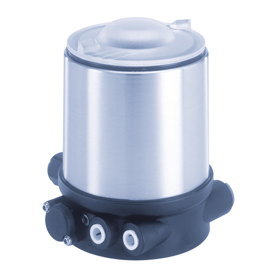
Type 8691 REV.2 Product description PRODUCT DESCRIPTION Transparent cap Structure Body casing The modular design of the device supports various configura- Air intake filter tions and variants. Fastening screw View without transparent cap: Display device status: high-power LEDs Basic housing Pilot valve LED Fig. 2: Structure, integrated pilot air duct Status LED Pilot air port, label: 1 5.1.2 Structure, external pilot air duct (20xx, Exhaust air port, label: 3 Classic) Fastening screw The structure with external pilot air duct is optimized for mounting Pressure limiting valve on process valves of the 20xx series (Classic). -
Page 8: Technical Data
Type 8691 REV.2 Technical data TECHNICAL DATA 6.4.2 UL type label Features of the type code applicable to UL and ATEX Conformity Type Control function, pilot valve, The device conforms to the EU directives as per the EU Declaration supply voltage pilot valve of Conformity (if applicable). 8691 -E3-...-0 Max. operating pressure single act pilot 3,0 24V Pmax 7bar Standards Ambient temperature, version Tamb -10 - +55°C REV.2 Ser.-Nr. 001000 Serial number, CE marking The applied standards, which are used to demonstrate conformity W14UN 00179024 Order number, manufacture code with the EU Directives, are listed in the EU type examination cer- Barcode tificate and/or the EU Declaration of Conformity (if applicable). Fig. 5: UL type label (example) Approvals 6.4.3 UL additional label... - Page 9 Type 8691 REV.2 Technical data 6.5.1 Fluidic data 6.5.2 Electrical data NOTE Control medium Neutral gases, air For variants with cULus approval, please note: Quality classes as per ISO 8573-1 ▶ Only use circuits of limited power as per UL NEC Class 2. Dust content Class 7 Max. particle size 40 µm, max. particle density 10 mg/m³ Water content class 3 Max. pressure dew point -20°C or 6.5.2.1 Electrical data, IO-Link min. 10°C below lowest operating temperature Protection class 3 as per DIN EN 61140 (VDE 0140-1) Oil content Class X Max. 25 mg/m³ Connection...
-
Page 10: Mechanical Data
Type 8691 REV.2 Technical data 6.5.2.2 Electrical data, büS 6.6.1 Safety end positions Safety end positions after failure of the electrical or pneumatic Protection class 3 as per DIN EN 61140 (VDE 0140-1) auxiliary power: Connection Circular plug-in connector M12 x 1, 5-pin Actuator Designation Safety end positions after Operating voltage 18–30 V DC (according to system failure of the auxiliary power specification) electrical pneumatic Max. current consumption120 mA @18 V (incl. inrush current pilot valve for 200 ms) single-acting down down Current consumption input 95 mA @18 V control function A during normal operation (after current reduction, down pilot valve after 200 ms... -
Page 11: Mechanical Installation
Type 8691 REV.2 Mechanical installation MECHANICAL INSTALLATION NOTE Safety instructions Damage to the device and the drive when welding welded bodies. DANGER Observe the following during installation on process valves with Risk of injury from high pressure and discharge of medium. welded body: ▶ Before working on the device or system, switch off the pres- ▶ Observe the installation instructions for the operating manual sure. Vent or drain lines. of the process valve. - Page 12 Type 8691 REV.2 Mechanical installation → To secure the switch spindle, apply some screw locking paint Puck (e.g. Loctite 290) in the threading of the spindle extension in the actuator. Switch spindle → Check that the O-ring is in the correct position. Guide element → Screw guide element in actuator cover (tightening torque: Lip seal max. 5 Nm). Max. 1 Nm → Screw switch spindle onto the spindle extension. A slot is provided on the top side (tightening torque: max. 1 Nm). Max. 5 Nm → Push puck onto the switch spindle and lock into position. Actuator cover O-ring 2. Attaching the form seal Spindle extension → Pull the form seal onto the actuator cover (smaller diameter Fig. 8: Installing the switch spindle (2), integrated pilot air duct points upwards).
-
Page 13: Installing Devices With External Control Air Duct (20Xx, Classic)
Type 8691 REV.2 Mechanical installation → Attach device to the actuator using the two side fastening 3. Installing the device screws. In doing so, tighten the screws only hand-tight (max. NOTE torque: 1.5 Nm). Damage or functional outage of the PCB. ▶ Ensure that the puck lies flat in the guide rail. → Align the puck and device so that: Connection piece 1. The puck rests in the guide rail of the device (see Fig. 2x fastening below). screw 2. Find the connection pieces of the device into the pilot air Pilot air ports (max. 1.5 Nm) ports of the actuator (see second Fig. below). Guide rail Fig. 11: Installation Installing devices with external control air duct (20xx, Classic) Only for devices without preinstalled process valve. - Page 14 Type 8691 REV.2 Mechanical installation → Press O-ring down into the actuator cover. 1. Installing switch spindle → Manually screw the switch spindle (and the slipped over Transparent cap guide element) to the spindle of the actuator with the plastic part and do not tighten initially. Position indicator → Screw the guide element into the cover of the actuator with a face pin wrench* (tightening torque: max. 8 Nm). → Tighten the switch spindle on the spindle of the actuator. A slot is provided on the top side (tightening torque: max. 1 Nm). → Push puck onto the switch spindle and lock into position. Actuator 2. Installing the device Fig.
- Page 15 Type 8691 REV.2 Mechanical installation NOTE NOTE Damage or malfunction due to ingress of dirt or moisture. Damage or functional outage of the PCB. ▶ Ensure that the puck lies flat in the guide rail. To observe the degree of protection IP65 or IP67: ▶ Tighten fastening screws only with a tightening torque of max. 1.5 Nm. → Align the puck and the device so that the puck rests in the guide rail of the device (see following figure). → Attach device to the actuator using the two side fastening screws. In doing so, tighten the screws only hand-tight (max. Guide rail torque: 1.5 Nm). 3. Pneumatically connecting device and actuator...
- Page 16 Type 8691 REV.2 Mechanical installation NOTE Control function I (CFI) Process valve closed in resting position Damage or malfunction due to ingress of dirt or moisture. Device Pilot air outlet To observe the degree of protection IP65 or IP67: ▶ Only for CFA and CFB: Connect the pilot air outlet which is Actuator Upper pilot air port not required to the free pilot air port of the actuator or seal Lower pilot air port with a plug. Control function A (CFA) Process valve closed in resting position (by spring force) Control function I (CFI)
-
Page 17: Aligning (Turning) The Device And Position Of Connections
Type 8691 REV.2 Mechanical installation Aligning (turning) the device and position of connections Devices with integrated pilot air duct: Alignment of device and position of connections is only Actuator Actuator possible with 2100, 2101 and 2106 process valves. Hexnut The device and position of the connections can be aligned Hexnut Body connection Body connection - turning the actuator Valve body Valve body Devices with external pilot air duct: Fig. 17: Turning the actuator (1) The device and position of the connections can be aligned →... - Page 18 Type 8691 REV.2 Mechanical installation DANGER Device Risk of injury from high pressure and discharge of medium. Fastening screw (2x) If the direction of rotation is wrong, the body connection may become detached. ▶ Only turn the actuator is the prescribed direction. Pneumatic connection Actuator → Move the actuator to the required position by turning it counter-clockwise (viewed from below). Fig. 19: Turning the device → Loosen pneumatic connection between device and actuator. → Release fastening screws (hex socket bolt SW2.5). → Rotate the device into the required position. NOTE Damage or malfunction due to ingress of dirt or moisture.
-
Page 19: Pneumatic Installation
Type 8691 REV.2 Pneumatic installation → Only tighten the fastening screws until they are hand-tight PNEUMATIC INSTALLATION (max. torque: 1.5 Nm). Safety instructions → Re-establish pneumatic connections between device and actuator. If necessary, use longer hoses. DANGER Risk of injury from high pressure and discharge of medium. ▶ Before working on the device or system, switch off the pres- sure. Vent or drain lines. WARNING Risk of injury from improper installation. ▶ Only trained technicians may perform installations. ▶ Perform installations with suitable tools only. -
Page 20: Connecting The Device Pneumatically
Type 8691 REV.2 Electrical installation Connecting the device pneumatically ELECTRICAL INSTALLATION Safety instructions for electrical installation Exhaust air port, label: 3 DANGER Risk of injury from electric shock. ▶ Before working on the device or system, switch off the power Pilot air port, label: 1 supply. Secure against reactivation. ▶ Observe applicable accident prevention and safety regula- Fig. 20: Connecting the device pneumatically tions for electrical equipment. Important information for the problem-free functioning... -
Page 21: Connecting The Device Electrically,Io-Link
Type 8691 REV.2 Electrical installation Connecting the device electrically, Connecting the device electrically, IO-Link büS Fig. 21: Pin assignment Fig. 22: Pin assignment Designation Assignment Wire color Assignment IO-Link mode SIO mode CAN plate/shielding CAN plate/shielding 24 V DC +24 V DC ± 10%, max. residual ripple 10% Not assigned DI or DO black GND / CAN_GND L −... -
Page 22: Start-Up
Type 8691 REV.2 Start-up START-UP Closing device: Transparent cap 10.1 Teach function: Determine end Seal positions and save these, REV.2 (body casing) Body casing • Automatic teach function: For devices with pilot valve The teach function automatically identifies and saves the end Basic housing positions of the valve. • Manual teach function: For devices without pilot valve Actuator The end positions are captured and saved automatically. Fig. 23: Opening or closing the device NOTE 10.1.1 Automatic teach function... - Page 23 Type 8691 REV.2 Start-up 10.1.2 Manual teach function → When the red status LED starts blinking, release the button within 5 seconds. For devices without pilot valve: The end positions are captured and saved manually by the user. W hen the red status LED stops blinking, the teach function is terminated. With the IO-Link variant, the teach function can also be T he end positions of the valve have been identified and started with an acyclic IO-Link parameter (see parameter saved. list) or with the Bürkert Communicator. → Check that the seal (body casing) is in the correct position. With the büS variant, the teach function can also be NOTE started with the Bürkert Communicator. Damage or malfunction due to ingress of dirt or moisture. Essential requirements: To observe the degree of protection IP65 or IP67: •...
- Page 24 Type 8691 REV.2 Start-up → Check whether the pneumatic actuator is in the deaerated, NOTE unactuated end position. Breakage of the pneumatic connection pieces due to rota- → This end position is confirmed by briefly pressing the button. tional impact. Yellow pilot valve LED is lit. ▶ When opening or closing the device, do not press against the → Move the pneumatic actuator into the aerated, switched end actuator, but against the basic housing. position. → This end position is confirmed by briefly pressing the button. → Screw off the body casing by turning counterclockwise. Yellow pilot valve LED is not lit. Pilot valve LED (V) → Air bleed the pneumatic actuator: move to the unactuated end position. Status LED (red) Yellow pilot valve LED is lit. Status LED (green)
-
Page 25: 10.2 Setting With Bürkert Communicator
Type 8691 REV.2 Start-up → Check that the seal (body casing) is in the correct position. Closing device: Transparent cap NOTE Seal (body casing) Damage or malfunction due to ingress of dirt or moisture. Body casing To observe the degree of protection IP65 or IP67: ▶ Screw in body casing to the stop. Basic housing → Close the device (wrench*: 674077). Actuator Fig. 27: Opening or closing the device 10.2 Setting with Bürkert Communicator NOTE The Bürkert Communicator can be used to make all settings on... -
Page 26: 10.3 Io-Link
Type 8691 REV.2 Start-up → Insert micro USB plug in büS service interface. 10.3 IO-Link → Establish connection to PC with büS stick. 10.3.1 Information, IO-Link → Starting Bürkert Communicator IO-Link is an internationally standardized IO technology (IEC → Implementing settings. 61131-9) to enable sensors and actuators to communicate. IO-Link is a point-to-point communication with 3-wire connection technology for sensors and actuators and unshielded standard 10.2.2 Connecting büS device with Bürkert sensor cables. Communicator Required components: 10.3.2 Technical specifications, IO-Link • Communications software: Bürkert Communicator for PC • büS standard set (see accessories) IO-Link specifications V1.1.2... -
Page 27: 10.4 Büs
Type 8691 REV.2 Start-up 10.4 büS 10.3.3 Interfaces, IO-Link 10.4.1 Information, büS büS is a system bus developed by Bürkert with a communication Control head büS service Supply protocol based on CANopen. interface 8691 IO-Link IO-Link, SIO mode 10.4.2 Interfaces, büS Fig. 29: Interfaces Supply Control head büS 8691 büS büS service interface (micro USB plug) Fig. 31: Interfaces Fig. 30: büS service interface 10.4.3 Configuration of the fieldbus... -
Page 28: Operation
Type 8691 REV.2 Operation OPERATION NOTE 11.1 Display device status, IO-Link and büS Damage or malfunction due to ingress of dirt or moisture. To observe the degree of protection IP65 or IP67: Following device statuses are indicated with LEDs: ▶ Screw in transparent cap to the stop. • Pilot valve LED: Activation of pilot valve • Device status LED: Valve position, errors, warnings Closing device: • Status LED green: IO-Link mode Transparent cap Seal • Status LED red: Teach function, error (body casing) Body casing... - Page 29 Type 8691 REV.2 Operation 11.1.2 Status LED, green and red IO-Link: The LED mode and the colors of the valve position can be set with an acyclic IO-Link parameter (see parameter list) or with the Color Status Description Bürkert Communicator. green is lit büS: green is not lit IO-Link communication inactive The LED mode and the colors of the valve position can be set green blinking IO-Link communication active with the Bürkert Communicator. Tab. 7: IO-Link status LED, green The description for setting the LED mode can be found in the section "Setting the LED mode" in the operating manual. Color Status Description...
- Page 30 Type 8691 REV.2 Operation 11.1.3.2 Valve mode + errors Valve Valve position Device status: Error position status, color status, color Displays in valve mode + errors: • Valve position: open, half-way, closed Open is lit yellow* blinks alternately red and yellow* • Device status: Error Half-way LED off* blinks alternately red and white* Closed is lit green* blinks alternately red and green* Valve Valve position Device status: Error Tab.
- Page 31 Type 8691 REV.2 Operation Valve Valve position Device status: Maintenance required Status display in accordance with NE 107, edition 2006-06-12 position status, color status, color Color Color Status Description Open is lit yellow* blinks alternately blue and yellow* code Outage, error Normal operation is not pos- Half-way LED off* blinks alternately blue and white* or malfunction sible due to a malfunction in...
-
Page 32: Switching The Device Manually With Pilot Valve
Type 8691 REV.2 Operation 11.2 Switching the device manually with Switching the device: pilot valve The device can be switched manually with the pilot valve when Manual override the control air is connected. Pilot valve Opening the device: Transparent cap Basic housing Body casing Fig. 35: Manually switching the device Basic housing NOTE Damage to the manual override by pressing and rotating at Actuator the same time. -
Page 33: Deinstallation
Type 8691 REV.2 Deinstallation DEINSTALLATION Closing the device: 12.1 Safety instructions deinstallation Body casing DANGER Risk of injury from high pressure and discharge of medium. Seal ▶ Before working on the device or system, switch off the pres- (body casing) sure. Vent or drain lines. Basic housing DANGER Fig. 37: Closing the device Risk of injury from electric shock. -
Page 34: 12.2 Deinstallation
Type 8691 REV.2 Spare parts, accessories 12.2 Deinstallation SPARE PARTS, ACCESSORIES Body casing Fastening screws Designation Order no. Special wrench 665702 Circular plug-in Wrench for opening/closing the transparent cap 674077 Basic housing connector Communication software Bürkert Communicator Information at www. buerkert.de Pneumatic USB-büS interface set: connection büS standard set (büS stick + 0.7 m cable with M12 772551 Pilot air port Actuator plug) External pilot air Exhaust air port duct (Classic) büS adapter for büS service interface 773254 Integrated pilot air duct (Element) (M12 on büS service interface Micro-USB) -
Page 35: Communications Software
Type 8691 REV.2 Transportation, storage, disposal 13.1 Communications software TRANSPORTATION, STORAGE, DISPOSAL The Bürkert Communicator PC program is designed for com- munication with Type 8691 devices with fieldbus control via NOTE DeviceNet, IO-Link or büS. Devices from year of construction Damage in transit due to inadequately protected devices. April 2014 support the full range of functions. ▶ Protect the device against moisture and dirt in shock-resis- For questions regarding compatibility, please contact the Bürkert tant packaging during transportation. Sales Center. ▶ Observe permitted storage temperature. A detailed description for installing and operating the software can be found in the associated operating instructions. NOTE Incorrect storage may damage the device. - Page 36 Type 8691 REV.2 Transportation, storage, disposal English...
- Page 38 www.burkert.com...
Need help?
Do you have a question about the 8691 REV.2 and is the answer not in the manual?
Questions and answers