
Related Manuals for Sungrow SG25CX-P2


Summary of Contents for Sungrow SG25CX-P2
- Page 1 User Manual PV Grid-Connected Inverter SG25CX-P2 /SG30CX-P2 / SG33CX-P2 / SG36CX-P2 / SG40CX-P2/ SG50CX-P2 SG25CX-P2 /SG30CX-P2 / SG33CX-P2 / SG36CX- P2 / SG40CX-P2/ SG50CX-P2PV Grid-Connected InverterUser ManualSG25_30_33_36_40_50CX- P2-UEN-Ver16-202310 SG25_30_33_36_40_50CX-P2-UEN-Ver16-202310...
-
Page 3: All Rights Reserved
Software Licenses • It is prohibited to use data contained in firmware or software developed by SUNGROW, in part or in full, for commercial purposes by any means. • It is prohibited to perform reverse engineering, cracking, or any other operations that... -
Page 4: About This Manual
Please read this manual carefully before using the product and keep it properly at a place for easy access. All contents, pictures, marks, and symbols in this manual are owned by SUNGROW. No part of this document may be reprinted by the non-internal staff of SUNGROW without written... - Page 5 Contents of this manual may be periodically updated or revised, and the actual product pur- chased shall prevail. Users can obtain the latest manual from support.sungrowpower.com or sales channels. Symbols This manual contains important safety instructions, which are highlighted with the following symbols, to ensure personal and property safety during usage, or to help optimize the prod- uct performance in an efficient way.
-
Page 7: Table Of Contents
Contents All Rights Reserved .....................I About This Manual......................II 1 Safety Instructions ....................1 1.1 Unpacking and Inspection ................2 1.2 Installation Safety ...................2 1.3 Electrical Connection Safety................3 1.4 Operation Safety ....................4 1.5 Maintenance Safety ..................5 1.6 Disposal Safety ....................6 2 Product Description ..................7 2.1 System Introduction ..................7 2.2 Product Introduction..................9... - Page 8 4.5.3 Pole Installation ..................28 4.6 Installing the Inverter..................29 4.7 Installing Optimizer(Optional) ................31 5 Electrical Connection ..................33 5.1 Safety Instructions ..................33 5.2 Terminal Description ..................35 5.3 Electrical Connection Overview ..............36 5.4 Crimp OT/DT terminal ...................38 5.5 External Protective Grounding Connection .............39 5.5.1 External Protective Grounding Requirements ........40 5.5.2 Connection Procedure.................40 5.6 AC Cable Connection ...................41...
- Page 9 6.2 Commissioning Procedure ................69 6.3 Optimizer Physical Layout (Optional) .............70 7 iSolarCloud App ....................71 7.1 Brief Introduction ..................71 7.2 Installing App ....................71 7.3 Function Overview..................72 7.4 Device Initialization..................72 7.4.1 Requirements ..................72 7.4.2 Initialization Procedure ................73 7.5 View Device Information................78 7.5.1 Check Device Status ................78 7.5.2 View Run Information ................80 7.5.3 View Records ..................81 7.6 More......................83...
- Page 10 8.2 Dismantling the Inverter ................111 8.3 Disposal of Inverter..................112 9 Troubleshooting and Maintenance ............113 9.1 Troubleshooting ..................113 9.2 Maintenance ....................122 9.2.1 Maintenance Notices................. 122 9.2.2 Quick Shutdown................123 9.2.3 Routine Maintenance ................ 124 9.2.4 Cleaning Air Inlet and Outlet............... 124 9.2.5 Fan Maintenance ................
-
Page 11: Safety Instructions
Perform operations considering ac- tual onsite conditions. • SUNGROW shall not be held liable for any damage caused by violation of gen- eral safety operation requirements, general safety standards, or any safety in- struction in this manual. -
Page 12: Unpacking And Inspection
If there are problems with the above inspection items, do not install the device and contact your distributor first. If the problem persists, con- tact SUNGROW in time. Installation Safety •... -
Page 13: Electrical Connection Safety
User Manual 1 Safety Instructions Electrical Connection Safety • Before electrical connections, please make sure that the inverter is not dam- aged, otherwise it may cause danger! • Before electrical connections, please make sure that the inverter switch and all switches connected to the inverter are set to "OFF", otherwise electric shock may occur! The PV string will generate lethal high voltage when exposed to sunlight. -
Page 14: Operation Safety
1 Safety Instructions User Manual • Check the positive and negative polarity of the PV strings, and connect the PV connectors to corresponding terminals only after ensuring polarity correctness. • During the installation and operation of the inverter, please ensure that the posi- tive or negative poles of PV strings do not short-circuit to the ground. -
Page 15: Maintenance Safety
To avoid the risk of electric shock, do not perform any other maintenance opera- tions beyond those described in this manual. If necessary, contact your distributor first. If the problem persists, contact SUNGROW. Otherwise, the losses caused is not covered by the warranty. -
Page 16: Disposal Safety
1 Safety Instructions User Manual • If the paint on the inverter enclosure falls or rusts, repair it in time. Otherwise, the inverter performance may be affected. • Do not use cleaning agents to clean the inverter. Otherwise, the inverter may be damaged, and the loss caused is not covered by the warranty. -
Page 17: Product Description
PV strings without grounding. Connected to the PV module by its input cable, the optimizer Optimizer can track the module's maximum power and output the de- sired voltage through a DC/DC voltage conversion circuit. SG25CX-P2, SG30CX-P2, SG33CX-P2, SG36CX-P2, Inverter SG40CX-P2, SG50CX-P2... - Page 18 2 Product Description User Manual Description Item Note Grid connection Includes devices such as AC circuit breaker, SPD, metering cabinet device. Raises the output voltage of the inverter to a level that meets Transformer the requirements of the grid. The grid forms supported by the inverter are shown in the fig- Utility grid ure below.
-
Page 19: Product Introduction
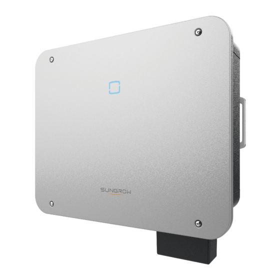
User Manual 2 Product Description Product Introduction Model Description The model description is as follows (take SG30CX-P2 as an example): Appearance The following figure shows the appearance of the inverter. figure 2-2 Appearance The image shown here is for reference only. The actual product received may differ. Description Name To indicate the current working state of the inverter. -
Page 20: Symbols On Product
2 Product Description User Manual Dimensions The following figure shows the dimensions of the inverter. figure 2-3 Product Dimensions(in mm) Weight Model Dimensions (W*H*D) Weight SG25/30/33CX-P2 38 kg SG36/40CX-P2 40 kg 645*575*245 mm SG50CX-P2 41 kg SG30CX-P2(For Australia) 35 kg 600*625*240 mm SG50CX-P2(For Australia) 36 kg... -
Page 21: Led Indicator
User Manual 2 Product Description Symbol Explanation UKCA mark of conformity. The inverter does not have a transformer. Disconnect the inverter from all the external power sources be- fore maintenance! Burn danger due to the hot surface that may exceed 60°C. Danger to life due to high voltages! Do not touch live parts for 15 minutes after disconnection from the power sources. -
Page 22: Circuit Diagram
2 Product Description User Manual LED Color State Definition A fault occurs and the device cannot connect to the grid. The Bluetooth connection is established, data commu- Blink nication in process, and a system fault occurs. Both the AC and DC sides are powered down. Gray Voltage may still be present in AC side circuits after the indicator is off. -
Page 23: Function Description
• The communication accessory port is used to connect communication module manufac- tured by SUNGROW, and upload monitoring data through communication cables or wire- less communication. The inverter can be connected to communication devices via either of the two interfaces. - Page 24 2 Product Description User Manual The PID effect (Potential Induced Degradation) of PV modules will cause serious damage to generated output and yield, which can be avoided or recovered by PID recovery function. • For positive voltage scheme, after the PID is enabled, the voltage to ground of all PV strings is greater than 0, and therefore the PV string-to-ground voltage is a positive value.
- Page 25 User Manual 2 Product Description This function can be enabled to detect whether arc occurs in the DC circuit of the inverter. • AFCI self-test This function is intended to detect whether the AFCI function of the inverter is normal. •...
-
Page 26: Unpacking And Storage
• Check the inner contents for damage after unpacking. Contact SUNGROW or the transport company in case of any damage or incompleteness, and provide photos to facilitate services. Do not dispose of the original packing case. It is recommended to store the device in the original packing case when the product is decommissioned. - Page 27 User Manual 3 Unpacking and Storage • Do not store the inverter in places susceptible to direct sunlight, rain, and strong electric field. • Do not place the inverter in places with items that may affect or damage the inverter. •...
-
Page 28: Mechanical Mounting
Mechanical Mounting Respect all local standards and requirements during mechanical installation. Safety During Mounting Make sure there is no electrical connection before installation. Before drilling, avoid the water and electricity wiring in the wall. Poor installation environment will affect system performance! •... -
Page 29: Location Requirements
The ambient temperature and relative humidity must meet the following requirements. • Please consult SUNGROW before installing inverters outdoors in areas prone to salt damage, which mainly are coastal areas within 500 meters of the coast. The deposition of salt fog varies largely with nearby seawater characteristics, sea wind, precipitation, rel- ative humidity, terrain, and forest coverage. -
Page 30: Carrier Requirements
4 Mechanical Mounting User Manual • It is strictly prohibited to install the inverter in environments with vibration and strong elec- tromagnetic field. Strong-magnetic-field environments refer to places where magnetic field strength measures over 30A/m. • The inverter generates noise during operation and is not recommended to be installed in living areas. -
Page 31: Clearance Requirements
User Manual 4 Mechanical Mounting tilting backwards installation requirements In case the installation site is a level surface, mount the inverter to the horizontal-mounting bracket to meet the mounting angle requirements, as shown in the figure below. Take the following items into account when designing the bracket scheme: •... - Page 32 4 Mechanical Mounting User Manual *When this distance is less than the distance shown, lift the inverter off the stand or wall be- fore maintaining fans. The distance from the bottom of the inverter to the ground is determined according to the bending radius of the selected AC cable and the installation environment, and the following requirements should be met:...
-
Page 33: Installation Tools
User Manual 4 Mechanical Mounting Back-to-Back Installation When installing inverters back-to-back, the distance between every two inverters should be at least 200 mm. Add a baffle between the two inverters to form a heat dissipation channel. The baffle plate should be placed horizontally between two inverters and should not block the air outlet of inverters. -
Page 34: Moving The Inverter
4 Mechanical Mounting User Manual Safety shoes Utility knife Anti-static wrist strap Marker Level Hammer drill Rubber mallet Phillips screwdriver (φ12) (M4, M5, M6) Open-end wrench Socket wrench set Wire cutter Wire stripper (16 mm, 60 mm) (M8) Hydraulic plier Heat gun Crimping tool Connector wrench... -
Page 35: Installing Mounting-Bracket
User Manual 4 Mechanical Mounting • Always be aware of the weight of the inverter. • Prevent the inverter from tilting or dropping. Lift and move the inverter to the destination by using the side handles and bottom edge. Improper handling may cause personal injury! •... -
Page 36: Bracket-Mounted Installation
4 Mechanical Mounting User Manual 4.5.1 Bracket-Mounted Installation Tool preparation Name Specification — Marker Level Hammer drill Bit: φ12 Wrench Inner diameter: 16mm Material preparation Name Quantity Specification Source Bolt Included in the delivery assembly scope Not included in the delivery Steel u- channel scope... -
Page 37: Wall-Mounted Installation
User Manual 4 Mechanical Mounting - - End 4.5.2 Wall-Mounted Installation Tool preparation Name Specification — Maker Level Hammer drill Bit: φ12 Wrench Inner diameter: 16mm Material preparation Name Quantity Specification Source Expansion Not included in the delivery bolt scope Step 1 Place the mounting-bracket at the installation place, adjust the angle with a level, and mark the location of the drilled holes. -
Page 38: Pole Installation
4 Mechanical Mounting User Manual Step 3 Secure the mounting-bracket with expansion bolts. - - End 4.5.3 Pole Installation Tool preparation Name Specification — Marker Level Hammer drill* Bit: φ12 Wrench Inner diameter: 16mm *Check if tools of other specifications are needed according to the bolts of the matching clamps. -
Page 39: Installing The Inverter
User Manual 4 Mechanical Mounting Step 2 Mark and drill holes in steel u-channels according to the dimensions shown in the figure be- low. Two steel u-channels should be spaced 180 mm - 260 mm apart. Step 3 Secure the mounting-bracket to the steel u-channels with bolts. Step 4 Secure the steel u-channels to the pole with bolts and clamps. - Page 40 4 Mechanical Mounting User Manual Name Quantity Specification Source Cross screw M5×16 Included in the delivery scope Step 1 Take out the inverter from the packing case. Step 2 Lift the inverter onto the mounting-bracket and make sure the mounting ears fit well into the grooves of the mounting-bracket.
-
Page 41: Installing Optimizer(Optional)
User Manual 4 Mechanical Mounting Installing Optimizer(Optional) Step 1 As shown in the figure below, clamp the optimizer parallel to the back of the PV module by clips. Full configuration is supported, and partial configuration is not supported. The full configura- tion scenario is shown below: figure 4-2 Optimizers Configured for All PV Modules... - Page 42 4 Mechanical Mounting User Manual • Please ensure that the optimizer is installed facing the back of the module. Oth- erwise, the clip may get damaged. • Do not forcibly bend the clips when installing the optimizer by clips. Otherwise, the clip may be damaged.
-
Page 43: Electrical Connection
Electrical Connection Safety Instructions The PV string will generate lethal high voltage when exposed to sunlight. • Operators must wear proper personal protective equipment during electrical connections. • Must ensure that cables are voltage-free with a measuring instrument before touching DC cables. •... - Page 44 5 Electrical Connection User Manual All electrical connections must comply with local and national/regional electrical standards. • Cables used by the user shall comply with the requirements of local laws and regulations. • Only with the permission of the national/regional grid department, the inverter can be connected to the grid.
-
Page 45: Terminal Description
User Manual 5 Electrical Connection The cable colors in figures in this manual are for reference only. Please select ca- bles according to local cable standards. Terminal Description All electrical terminals are located at the bottom of the inverter. figure 5-1 Terminal Description * The image shown here is for reference only. -
Page 46: Electrical Connection Overview
5 Electrical Connection User Manual table 5-1 The label of COM2 terminal RS485 Meter D4/8 D2/6 PGND PGND D3/7 D1/5 table 5-2 The label description of COM2 terminal Description Label emergency stop dry contact • "AU"/"NZ": Demand response enabling device (DRED) •... - Page 47 User Manual 5 Electrical Connection table 5-3 Cable Requirements Specification Cable Di- Type Cable ameter Cross-sectional Area(mm (mm) Multi-core PV cable with a maximum with- DC cable 4.7 ~ 6.4 4 ~ 6 stand voltage of 1100V External Outdoor single- The same as that of the PE wire in grounding core copper wire...
-
Page 48: Crimp Ot/Dt Terminal
S) wire specified in the table. Other sizes of grounding cables that meet local standards and safety regulations can also be used for grounding connections. But SUNGROW shall not be held liable for any damage caused. Crimp OT/DT terminal Crimp OT/DT terminal 1. -
Page 49: External Protective Grounding Connection
User Manual 5 Electrical Connection figure 5-2 Aluminum Cable Connection 1. Copper to Aluminum adapter terminal 2. Flange nut 3. Aluminum cable Ensure that the selected terminal can directly contact with the copper bar. If there are any problems, contact the terminal manufacturer. Ensure that the copper bar is not in direct contact with the aluminum wire. -
Page 50: External Protective Grounding Requirements
AC side grounding terminal are reliably grounded. The grounding connection can be made by other means if they are in accordance with the local standards and regulations, and SUNGROW shall not be held liable for the possible consequences. -
Page 51: Ac Cable Connection
AC Circuit Breaker An independent circuit breaker or fuse should be installed on the output side of the inverter to ensure safe disconnection from the grid. Recommended Rated Recommended Rated Voltage Inverter Current SG25CX-P2 400V 63 A SG30CX-P2 400V 63 A SG33CX-P2... -
Page 52: Requirements For Ot/Dt Terminal
30. A maximum of 13 inverters can be connected in parallel if the PV module is equipped with optimizers. If SUNGROW Logger1000 is applied, please note that a maximum of 3500 optimizers can be connected. - Page 53 User Manual 5 Electrical Connection Step 2 Take out the AC junction box and loosen the swivel nut. After removing the seals, select one or more appropriate seals for use in combination according to the cable outer diameter, by referring to the table below. Lead the cable through the swivel nut, seal, and junction box successively.
- Page 54 5 Electrical Connection User Manual Step 5 Secure the wires to corresponding terminals. Gently pull the cable backwards to ensure firm connection. Observe the terminal layout on the block. Do not connect the phase wires to "PE" terminal or "N" terminal. Otherwise, unrecoverable damage to the inverter may follow.
- Page 55 User Manual 5 Electrical Connection Step 6 Secure the junction box. Ensure that the junction box is properly assembled. Failure to do so may affect the waterproof performance of the AC side, and the loss caused by this is not covered by the warranty.
-
Page 56: Dc Cable Connection
5 Electrical Connection User Manual Step 7 Gently pull the cable backwards to ensure firm connection, and fasten the swivel nut clockwise. - - End DC Cable Connection The PV string will generate lethal high voltage when exposed to sunlight. •... - Page 57 User Manual 5 Electrical Connection • Make sure the PV array is well insulated to ground before connecting it to the inverter. • Make sure the maximum DC voltage and the maximum short circuit current of any string never exceed inverter permitted values specified in "Technical Data". •...
-
Page 58: Pv Input Configuration
5 Electrical Connection User Manual Note the following items when laying out cables on site: • The axial tension on PV connectors must not exceed 80 N. Avoid axial cable stress on the connector for a long time during field wiring. •... -
Page 59: Assembling Pv Connectors
• Do not connect the AC circuit breaker before finishing electrical connection. SUNGROW provides corresponding PV connectors in the scope of delivery for quick connection of PV inputs. To ensure IP66 protection, use only the supplied connector or the connector with the same ingress of protection. -
Page 60: Installing Pv Connector
5 Electrical Connection User Manual Step 4 Tighten the cable gland and the insulator. Step 5 Check for polarity correctness. If the PV polarity is reversed, the inverter will be in a fault or alarm state and will not operate normally. - - End 5.7.3 Installing PV Connector Step 1 Ensure that the DC switch is in "OFF"... - Page 61 User Manual 5 Electrical Connection Step 2 Check the cable connection of the PV string for polarity correctness and ensure that the open circuit voltage in any case does not exceed the inverter input limit of 1,100 V. The multimeter must have a DC voltage range of at least 1100 V. If the voltage is a negative value, the DC input polarity is incorrect.
- Page 62 5 Electrical Connection User Manual Step 5 Connect the positive probe of a multimeter to OUT+ of the optimizer, and the negative probe of the multimeter to OUT- of the optimizer to check whether the optimizer is faulty. If the measured output voltage is 1 V, no fault occurs to the optimizer.
- Page 63 User Manual 5 Electrical Connection Step 6 When connecting multiple optimizers, connect OUT- of the first optimizer to OUT+ of the sec- ond optimizer, and so on. Use a multimeter to measure the optimizer voltage. If the meas- ured output voltage is 1 V*N (N is the number of optimizers), no fault occurs to the system. Whether connecting OUT+ of the first optimizer to OUT- of the second optimizer or connecting OUT- of the first optimizer to OUT+ of the second optimizer is depend- ent on the polarity of the extension cable that is connected to the inverter on site.
- Page 64 5 Electrical Connection User Manual Step 7 Connect OUT+ of the first optimizer and OUT- of the last optimizer to the PV input terminals of the inverter. If each PV module is equipped with an optimizer, the total power of PV modules in a PV input shall not exceed the maximum input power of a single PV input of the inverter.
-
Page 65: Communication Connection
*The image shown here is for reference only. The actual product you receive may differ. Once the communication module is in use, do not connect the inverter to a data logger at the same time via RS485. Please contact SUNGROW for any further queries. -
Page 66: Winet-S/Winet-S2 Connection (Optional)
5 Electrical Connection User Manual 5.8.2 WiNet-S/WiNet-S2 Connection (optional) The WiNet-S / WiNet-S2 module supports Ethernet communication and WLAN communication. It is not recommended to use both communication methods at the same time. For details, see the quick guide for the WiNet-S/WiNet-S2 module. Scan the following QR code for the quick guide. - Page 67 User Manual 5 Electrical Connection Step 3 Unscrew the housing from the communication module. Step 4 Thread the network cable through the swivel nut and gasket. Afterwards, route the cable into the opening of the sealing. Finally, insert the cable through the housing. Step 5 Insert the RJ45 plug into the front plug connector until there is an audible click and tighten the housing.
-
Page 68: Wlan Communication
5 Electrical Connection User Manual Step 6 Remove the waterproof lid from the COM1 terminal and install WiNet-S/WiNet-S2. Step 7 Slightly shake it by hand to determine whether it is installed firmly. - - End 5.8.2.2 WLAN Communication Step 1 Remove the waterproof lid from the COM1 terminal. Step 2 Install the module. -
Page 69: Assembling The Com Connector
5.8.3.1 Assembling the COM Connector SUNGROW cooperates with multiple suppliers on communication connectors, so there may be cases where two types of communication connectors are received. Both communication connectors are wired in the same way, and the actual product received shall prevail. - Page 70 5 Electrical Connection User Manual Step 2 Take out the terminal block. Step 3 Remove the seal and lead the cable through the cable gland. Step 4 Remove the cable jacket and strip the wire insulation. Step 5 Plug the wires into the RS485 terminal according the labels on the bottom of the inverter. Step 6 Pull the wires outward to check whether they are firmly installed.
-
Page 71: Installing The Com Connector
User Manual 5 Electrical Connection Step 7 Insert the terminal block into the connector until it snaps into place with an audible click. Step 8 Fasten the swivel nut. - - End 5.8.3.2 Installing the COM Connector Step 1 Remove the waterproof lid from the COM2 terminal. Step 2 Insert the COM connector into COM2 terminal on the bottom of the inverter until there is an audible click. -
Page 72: Smart Energy Meter Connection
For the setting of feed-in power limit, refer to the section "7.4.2 Initialization Procedure" Contact SUNGROW to ensure that the Smart Energy Meter model is available locally. This section mainly describes the cable connections on the inverter side. Refer to the quick guide delivered with the Smart Energy Meter for the connections on the meter side. - Page 73 User Manual 5 Electrical Connection DO terminal (fault output dry contact): The relay can be set to output fault alarms, and user can configure it to be a normally open contact (COM&NO). Use LED indicators or other equipment to indicate whether the inverter is in the faulty state. The following Figure shows the typical application of normally open contact : figure 5-5 Normally open contact •...
-
Page 74: Wiring Procedure
5 Electrical Connection User Manual The dry contacts only support passive switch signal input. The following figure shows the typical application of local stop dry contact. figure 5-6 Local stop contact figure 5-7 Daisy chain topology When wiring DI dry contacts, ensure that the maximum wiring distance meet the requirements in "10.2 Wring Distance of DI Dry Contact". - Page 75 Close S1 and S5 Enable the DRM function through the iSolarCloud APP. If there are any problems, contact your distributor first. If the problem persists, contact SUNGROW. The DRM function is only applicable to devices for Australia and New Zealand.
-
Page 76: Assembling The Com Connector
User Manual 5.8.6.1 Assembling the COM Connector SUNGROW cooperates with multiple suppliers on communication connectors, so there may be cases where two types of communication connectors are received. Both communication connectors are wired in the same way, and the actual product received shall prevail. - Page 77 User Manual 5 Electrical Connection Step 4 Remove the cable jacket by 7 mm–10 mm. Step 5 Plug the wires into the corresponding terminal according the labels on the bottom of the inverter. Step 6 Pull the wires outward to check whether they are firmly installed. Step 7 Insert the terminal block into the connector until it snaps into place with an audible click.
-
Page 78: Installing The Com Connector
5 Electrical Connection User Manual 5.8.6.2 Installing the COM Connector Step 1 Remove the waterproof lid from the COM2 terminal. Step 2 Insert the COM connector into COM2 terminal on the bottom of the inverter until there is an audible click. Step 3 Pull cables outwards to confirm whether they are fastened firmly. -
Page 79: Commissioning
Commissioning Inspection Before Commissioning Check the following items before starting the inverter: • All equipment has been reliably installed. • DC switch(es) and AC circuit breaker are in the "OFF" position. • The ground cable is properly and reliably connected. •... -
Page 80: Optimizer Physical Layout (Optional)
6 Commissioning User Manual Step 2 Close the AC circuit breaker between the inverter and the grid. Step 3 Install the iSolarCloud App, see "7.2 Installing App" for details. Step 4 Set initial protection parameters via the iSolarCloud App when the inverter is connected to the grid for the first time (see Step 4 in "7.4.2 Initialization Procedure"... -
Page 81: Isolarcloud App
iSolarCloud App Brief Introduction The iSolarCloud App can establish communication connection to the inverter via the Blue- tooth, thereby achieving near-end maintenance on the inverter. Users can use the App to view basic information, alarms, and events, set parameters, or download logs, etc. Screenshots in this manual are based on the Android system V2.1.6 , and the ac- tual interfaces may differ. -
Page 82: Function Overview
7 iSolarCloud App User Manual Systems equipped with SUNGROW optimizers can only work with SUNGROW com- munication devices and iSolarCloud App. Please use V2.1.6.20230411 or later ver- sions of iSolarCloud App. Function Overview The App provides parameter viewing and setting functions, as shown in the following figure. -
Page 83: Initialization Procedure
User Manual 7 iSolarCloud App 7.4.2 Initialization Procedure Step 1 Open the App to enter the login page, tap Local Access at the bottom of the page to go to the next page. - Page 84 7 iSolarCloud App User Manual Step 2 Establish the Bluetooth connection by either of the two following ways. If the LED indicator flashes blue, the connection is successfully established. If the inverter is configured with optimizers, log into iSolarCloud via WiNet-S2 or into the logger1000 Web to view and modify the parameters of the optimizer.
- Page 85 To set inverter parameters related to grid protection and grid support, contact your distributor to obtain the advanced account and corresponding password. If the distributor is unable to provide the required information, contact SUNGROW. Step 4 If the inverter is not initialized, you will enter the quick setting interface of initializing protection parameters.
- Page 86 7 iSolarCloud App User Manual Step 5 When the country is set to Australia, additionally set the applicable network service provider and then the grid type. Tap Power Company to select the correct power company. figure 7-5 Initialization Power Company The image shown here is for reference only.
- Page 87 User Manual 7 iSolarCloud App Grid Type Network Service Provider SA Power Networks • TS129-2019: < 10 kW for single-phase & 30 kW for three-phase • TS130-2017: > 30 kW & ≤ 200 kW • TS131-2018: > 200 kW Horizon Power •...
-
Page 88: View Device Information
7 iSolarCloud App User Manual View Device Information 7.5.1 Check Device Status Users can view the device’s operation information such as running status, power flow, and power curves on the Home screen. figure 7-6 Home Page table 7-3 Home Page Description Designation Description System date and time of the inverter... - Page 89 User Manual 7 iSolarCloud App Designation Description Curve showing change of power between 5 am and 23 pm every day Power curve (Each point on the curve represents the percentage of present inverter power to rated power) Including "Home", "Run Information", "Records", and Navigation bar "More"...
-
Page 90: View Run Information
7 iSolarCloud App User Manual 7.5.2 View Run Information Tap Run Information on the navigation bar to enter the screen showing running information, slide the screen upwards to view all detailed information. Run information includes PV information, inverter information, input and output information, etc. -
Page 91: View Records
User Manual 7 iSolarCloud App Classificat- Description Parameter Total Power Factor Power factor of the AC side of the inverter Gird Frenquency Frequency of the AC side of the inverter A-B Line Voltage B-C Line Voltage Line voltage C-A Line Voltage Phase A Current Phase B Current Phase current... - Page 92 7 iSolarCloud App User Manual figure 7-9 Detailed Fault Alarm Information Yield Record Tap Yield Record to enter the interface showing daily power generation as shown in the following figure. figure 7-10 Power Curve The App displays power generation records in a variety of forms, including daily power generation graph, monthly power generation histogram, annual power generation histogram.
-
Page 93: More
User Manual 7 iSolarCloud App Description Parameter Monthly yield Shows the power output every month in a year. histogram Annual yield Shows the power output every year. histogram Tap the time bar on the top of the interface to select a time segment and view the corresponding power curve. -
Page 94: Operation Parameters
7 iSolarCloud App User Manual figure 7-12 System Parameters * The image shown here is for reference only. Boot/Shutdown Tap Boot/Shutdown to send the boot/shutdown instruction to the inverter. Date Setting/Time Setting The correct system time is very important. Wrong system time will directly affect the data logging and power generation value. - Page 95 User Manual 7 iSolarCloud App figure 7-14 PID Parameters table 7-8 PID Parameter Description Description Parameter Enable/Disable the PID night recovery function. Once enabled, it PID Recovery works between 22:00 pm and 5:00 am by default. If ISO impedance abnormality or PID function exception is de- tected during running of the PID function, the inverter reports a Clear PID alarm PID abnormity and reminds the user to take corresponding meas-...
-
Page 96: Power Regulation Parameters
7 iSolarCloud App User Manual figure 7-16 Regular Parameters Setting 7.6.3 Power Regulation Parameters Active Power Regulation Tap “Settings→Power Regulation Parameters→Active Power Regulation” to enter the screen, as shown in the following figure. figure 7-17 Active Power Regulation table 7-9 Active Power Regulation Definition/Setting Range Parameter... - Page 97 User Manual 7 iSolarCloud App Definition/Setting Range Parameter Description Active power gradient Switch for enabling/disabling Enable/Disable control the active power rate settable function. Active power decline The decline rate of inverter ac- 1%/min~6000%/min gradient tive power per minute. Active power rising The rise rate of inverter active 1%/min~6000%/min gradient...
- Page 98 7 iSolarCloud App User Manual figure 7-18 Reactive Power Regulation table 7-10 Reactive Power Regulation Definition/Setting Range Parameter Description Reactive power gener- Switch for enabling/disabling Enable/Disable ation at night reactive power generation at night function. Reactive power ratio Reactive power ratio set for -100%~0%/ at night the reactive power generation...
- Page 99 User Manual 7 iSolarCloud App table 7-11 Descriptions of reactive power regulation mode: Descriptions Mode The PF is fixed at +1.000. The reactive power can be regulated by the parameter PF (Power Factor). The reactive power can be regulated by the parameter Q-Var limits (in %). Q(P) The PF changes with the output power of the inverter.
- Page 100 7 iSolarCloud App User Manual Explanation Range Parameter Voltage percentage for Q(P) function 100% ~ 110% EnterVoltage activation Voltage percentage for Q(P) function QP_ExitVoltage 90% ~ 100% deactivation Power percentage for Q(P) function QP_ExitPower 1% ~ 100% deactivation Unconditional activation/deactivation of Q QP_EnableMode Yes / No (P) function...
-
Page 101: Communication Parameters
User Manual 7 iSolarCloud App Explanation Range Parameter Grid voltage limit at P4 on the Q(U) mode QU_V4 100% ~ 120% curve Value of Q/Sn at P4 on the Q(U) mode QU_Q4 0 ~ 60% curve QU_EnterPower Active power for Q(U) function activation 20% ~ 100% QU_ExitPower Active power for Q(U) function deactivation... -
Page 102: Grounding Detection
If the distributor is unable to provide the required information, contact SUNGROW. Unauthorized personnel are not allowed to log in with this account. Otherwise, SUNGROW shall not be held liable for any damages caused. -
Page 103: Password Changing
User Manual 7 iSolarCloud App Tap “More→Settings→Operation Parameters→Grounding Detection” to enter the corre- sponding screen. figure 7-22 Grounding Detection If the grounding detection is enabled, the DO relay will switch on automatically to signal the external alarm if the value exceeds the grounding detection alarm value. The PV insulation resistance fault (fault sub-code 039) will trigger the DO relay to signal the external alarm. -
Page 104: Plant Creation And Device Management
7 iSolarCloud App User Manual Plant Creation and Device Management 7.7.1 Create an Account Step 1 Tap Register. Step 2 Select a Server, and choose to create a Retailer/Installer or Owner account according to the actual needs. Then, tap “Next”. Users in mainland China may choose Chinese Server and can only create a Distributor/Installer account. -
Page 105: Create A Plant
• You have already logged in to the iSolarCloud App. You can create an iSolarCloud account by yourself, or contact your distributor/installer or SUNGROW for the account and password. Devices are managed as part of a plant on the iSolarCloud App. You can add different types of devices to the plant, e.g., inverters, batteries, and communication modules. - Page 106 7 iSolarCloud App User Manual Step 1 Open the iSolarCloud App. Enter the account name and password on the login screen –> log into the account –> tap Create Plant –> fill in the general information of the plant –> save the settings.
-
Page 107: Connection
User Manual 7 iSolarCloud App Description Parameter City* The city where the plant is located. The postal code of the place where the plant is located. Postal Code Country/Region* The country (region) where the plant is located. The time zone of the place where the plant is located. Time Zone* The model of the PV module actually used in the plant. - Page 108 7 iSolarCloud App User Manual Step 1 Scan the QR code on the device to add it to the plant.
-
Page 109: Set Tariffs
User Manual 7 iSolarCloud App Step 2 Connect the communication device to the home network, so that data can be transferred to the iSolarCloud server over the home network. Tap Network –> enter the password –> press the button on the communication device once by following the onscreen instructions –>... - Page 110 7 iSolarCloud App User Manual Step 1 Set your preferred currency in Unit —> set Feed-in Tariff and Consumption Tariff —> save the settings. Step 2 Tap Complete. Now the steps for creating a plant are completed. - - End...
-
Page 111: Pv Plant Information
User Manual 7 iSolarCloud App 7.7.3 PV Plant Information Power Flow: Information such as generated output and feed-in power of the PV system are shown here. Arrows between the icons indicate that there is energy flowing between the devices. The direction in which the arrow points indicates the direction of the energy flow. Users granted access to live data can see the live data status: Live data enabled Live data not enabled... - Page 112 7 iSolarCloud App User Manual...
-
Page 113: Set Up Optimizer Layout (Optional)
User Manual 7 iSolarCloud App 7.7.4 Set up Optimizer Layout (Optional) 7.7.4.1 Single Inverter Scenario Step 1 Add an inverter: Choose the target plant, and tap “ →Layout Settings”. Then, tap at the bottom of this screen. Choose Inverter, and tap the blank area of the canvas. Set the number of inverters, and tap Add to add an inverter. - Page 114 7 iSolarCloud App User Manual Step 2 Add a PV module: at the bottom of the screen. Choose Generate From Image. Tap the plus button in the middle of the screen, and choose Take photo with camera or Select from album to upload the physical layout template.
- Page 115 User Manual 7 iSolarCloud App Check whether the optimizers have all been recognized successfully; if not, you may add them manually. Tap at the bottom of the screen, and choose PV Module. Tap the blank area of the canvas, complete the required information, and tap Add. Choose the module that has been added, and tap Assign to associate it with the corresponding S/N.
- Page 116 7 iSolarCloud App User Manual Step 4 Set up the logical layout: Tap Logic in the lower right corner of the screen. Select the target string. Tap or move the corresponding modules with your finger to arrange them in the right order according to the actual wiring of the optimizers.
-
Page 117: Multi-Inverter Scenario
User Manual 7 iSolarCloud App 7.7.4.2 Multi-inverter Scenario Step 1 Add an inverter: Choose the target plant, and tap “ →Layout Settings”. Then, tap at the bottom of this screen. Choose Inverter, and tap the blank area of the canvas. Set the number of inverters, and tap Add to add an inverter. -
Page 118: Optimizer Information
7 iSolarCloud App User Manual Step 5 Set Auto Frequency Point Setting to Disable, and modify the frequency point for Inverter 1 by referring to " Check Device Information". Step 6 Complete layout settings for the other inverters by referring to Steps 2 to 4 specified in this section. - Page 119 User Manual 7 iSolarCloud App View Power Yield Data at the upper right of the screen. You can choose Daily Yield, Monthly Yield, Annual Yield, or Total Yield to check the yield of each PV module. at the upper right of the screen. Choose Power to enable the live data function. You can then tap “...
- Page 120 7 iSolarCloud App User Manual • Tap an inverter on the screen to check its yield data. • Tap Information at the lower left of the screen to check the detailed device information such as General Information, Faults, Curve, Settings, and Remote Signaling Status. •...
-
Page 121: System Decommissioning
System Decommissioning Disconnecting Inverter Danger of burns! Even if the inverter is shut down, it may still be hot and cause burns. Wear protec- tive gloves before operating the inverter after it cools down. For maintenance or other service work, the inverter must be switched off. Proceed as follows to disconnect the inverter from the AC and DC power sources. -
Page 122: Disposal Of Inverter
8 System Decommissioning User Manual Step 1 Refer to "5 Electrical Connection" to disconnect all cables in reverse steps. In particular, when removing the DC connector, use a connector wrench to loosen the locking parts and install waterproof plugs. Step 2 Refer to"4 Mechanical Mounting", to dismantle the inverter in reverse steps. -
Page 123: Troubleshooting And Maintenance
App or the LCD. Modify the overvoltage protection values with the con- sent of the local electric power operator. 3. Contact Sungrow Customer Service if the pre- ceding causes are ruled out and the fault persists. Generally, the inverter will be reconnected to the grid after the grid returns to normal. - Page 124 2. Check whether the protection parameters are appropriately set via the App or the LCD. 3. Contact Sungrow Customer Service if the pre- ceding causes are ruled out and the fault persists. Generally, the inverter will be reconnected to the grid after the grid returns to normal.
- Page 125 App or the LCD. 3. Contact Sungrow Customer Service if the pre- ceding causes are ruled out and the fault persists. 1. Check whether the corresponding string is of reverse polarity.
- Page 126 3. Check if the DC fuse is damaged. If so, replace Alarm the fuse. 4. Contact Sungrow Customer Service if the pre- ceding causes are ruled out and the alarm persists. *The code 548 to code 563 are corresponding to string 1 to string 16 respectively.
- Page 127 If so, replace the dam- aged cable and secure terminals to ensure a reli- able connection. 5. Contact Sungrow Customer Service if the pre- ceding causes are ruled out and the fault persists. 1. Check whether the AC cable is correctly connected.
- Page 128 2. Reconnect the communication cable of the cation Abnormal meter. Alarm 3. Contact Sungrow Customer Service if the pre- ceding causes are ruled out and the alarm persists. 1. Check whether the output port is connected to actual grid. Disconnect it from the grid if so.
- Page 129 Close the AC and DC switches in turn 15 248–255, 300– minutes later and restart the system. 322, 324–328, 3. Contact Sungrow Customer Service if the pre- 401–412, 600– ceding causes are ruled out and the fault persists. 603, 605, 608, 612, 616, 620, 622–624, 800,...
- Page 130 Close the AC and DC switches in turn 15 364-395 minutes later and restart the system. Overvoltage Fault 2. If the fault persists, please contact Sungrow Power Customer Service. 1. Check whether the number of PV modules of the corresponding string is less than other strings.
- Page 131 1. Check the light condition, and update the opti- The opti- mizer soft- mizer again if the light is normal. Update 1024 ware fails failed 2. If the fault persists, please contact Sungrow to upgrade Customer Service.
-
Page 132: Maintenance
If there is a string current backfeed fault, first check whether the optimizer is offline. • Contact the dealer if the measures listed in the “Troubleshooting Method” col- umn have been taken but the problem persists. Contact SUNGROW if the dealer fails to solve the problem. Maintenance 9.2.1 Maintenance Notices Risk of inverter damage or personal injury due to incorrect service! •... -
Page 133: Quick Shutdown
To avoid the risk of electric shock, do not perform any other maintenance opera- tions beyond this manual. If necessary, contact your distributor first. If the problem persists, contact SUNGROW. Otherwise, the losses caused is not covered by the warranty. -
Page 134: Routine Maintenance
9 Troubleshooting and Maintenance User Manual 9.2.3 Routine Maintenance Item Method Period Check whether the air outlet and heat sink are blocked by dust and other Six months to a year objects. Device clean (depend on the dust con- Check if the air inlet and outlet are tents in air) normal. - Page 135 User Manual 9 Troubleshooting and Maintenance Fans inside the inverter are used to cool the inverter during operation. If the fans do not op- erate normally, the inverter may not be cooled down and inverter efficiency may decrease. Therefore, it is necessary to clean dirty fans and replace the broken fans in a timeiy manner. The operation procedure is as follows: Step 1 Stop the inverter(see"8.1 Disconnecting...
-
Page 136: Appendix
10 Appendix 10.1 Technical Data SG25CX- SG30CX- SG33CX- SG36CX- SG40CX- SG50CX- Parameters Input (DC) Recom- mended 35 kWp 42 kWp 46.2 kWp 50.4 kWp 56 kWp 70 kWp max. PV in- put power Max. PV in- 1100 V put voltage Min. - Page 137 User Manual 10 Appendix SG25CX- SG30CX- SG33CX- SG36CX- SG40CX- SG50CX- Parameters Max. DC 120 A (40 A * 3) 160 A (40 A * 4) short-circuit current Max. current for DC connector Output (AC) Rated AC output 25 kW 30 kW 33 kW 36 kW 40 kW...
- Page 138 10 Appendix User Manual SG25CX- SG30CX- SG33CX- SG36CX- SG40CX- SG50CX- Parameters Power fac- tor at Rated > 0.99 / 0.8 leading – 0.8 lagging power / Ad- justable power factor Feed-in phases / 3 / 3-N-PE connection phases Efficiency Max. effi- ciency / 98.4% / 98.5% / 98.3%...
- Page 139 User Manual 10 Appendix SG25CX- SG30CX- SG33CX- SG36CX- SG40CX- SG50CX- Parameters PV String current monitoring Arc fault cir- cuit inter- rupter (AFCI) PID recov- ery function General Data Dimensions 645*575*245 mm (W*H*D) Wall-mounting bracket Mounting Method Weight 38 kg 40 kg 40 kg 41 kg Topology...
- Page 140 10 Appendix User Manual SG25CX- SG30CX- SG33CX- SG36CX- SG40CX- SG50CX- Parameters Max. oper- ating 4000 m altitude Display LED, Bluetooth+APP Optimizer SP600S (Optional) Communi- RS485 / Optional: WLAN, Ethernet cation DC connec- EVO2 (Max. 6 mm² ) tion type AC connec- OT or DT tion type terminal...
- Page 141 User Manual 10 Appendix SG50CX-P2 (3) Parameters SG30CX-P2 (3) No. of PV strings per MPPT 90 A (30 A / 30 A / 30 A) 120 A (30 A / 30 A / 30 A / Max. PV input current 30 A) 120 A (40 A / 40 A / 40 A) 160 A (40 A / 40 A / 40 A /...
- Page 142 10 Appendix User Manual SG50CX-P2 (3) Parameters SG30CX-P2 (3) Overvoltage Category DC II / AC III Frequency Shift Active Anti-Islanding Method General Data 600*625*240 mm Dimensions (W*H*D) 35 kg 36 kg Weight Transformerless Topology IP66 Degree of protection Corrosion ≤5 W Night power consumption -30 to 60 ℃...
- Page 143 User Manual 10 Appendix SG25CX- SG30CX- SG33CX- SG36CX- SG40CX- SG50CX- Parameters Max. PV in- 1100 V put voltage Min. PV in- put voltage / 160 V / 200 V Startup in- put voltage Rated PV input 600 V voltage MPP volt- 160 V ~ 1000 V age range MPP volt-...
- Page 144 10 Appendix User Manual SG25CX- SG30CX- SG33CX- SG36CX- SG40CX- SG50CX- Parameters Max. AC 33 kVA 27.5 kVA 36.3 kVA 40 kVA 44 kVA 55 kVA output (7) power Max. AC 41.8 A 50.2 A 55.2 A 60.2 A 66.9 A 83.6 A output current...
- Page 145 User Manual 10 Appendix SG25CX- SG30CX- SG33CX- SG36CX- SG40CX- SG50CX- Parameters Max. effi- 98.4% / ciency / 98.5% / 98.3% European 98.2% efficiency Protection Grid monitoring DC re- verse con- nection pro- tection AC short- circuit protection Leakage current protection Surge DC Type I+II / AC Type II protection...
- Page 146 10 Appendix User Manual SG25CX- SG30CX- SG33CX- SG36CX- SG40CX- SG50CX- Parameters Degree of IP66 protection Corrosion Operating ambient -30 to 60 ℃ temperature range Allowable relative hu- midity range 0 – 100 % (non- condensing) Cooling Smart forced air cooling method Max.
-
Page 147: Wring Distance Of Di Dry Contact
User Manual 10 Appendix • The voltage of the configured string should be higher than the lower limit of the rated MPPT voltage. Note(7): 30kVA for Germany, Belgium, Austria, Ukraine and Denmark, 33kVA for others. 10.2 Wring Distance of DI Dry Contact The wiring distance between DI dry contact terminals must meet the requirements in the ta- ble below. -
Page 148: Quality Assurance
• The customer shall give SUNGROW a reasonable period to repair the faulty device. Exclusion of Liability In the following circumstances, SUNGROW has the right to refuse to honor the quality guarantee: • The free warranty period for the whole machine/components has expired. -
Page 149: Contact Information
User Manual 10 Appendix • The fault or damage is caused by the use of non-standard or non-SUNGROW compo- nents or software. • The installation and use range are beyond stipulations of relevant international standards. • The damage is caused by unexpected natural factors. - Page 150 Sungrow Power Supply Co., Ltd. www.sungrowpower.com...
Need help?
Do you have a question about the SG25CX-P2 and is the answer not in the manual?
Questions and answers