
Related Manuals for Sungrow SG250K3


Summary of Contents for Sungrow SG250K3
- Page 1 SG250K3 Grid-Connected Inverter Operation Manual SG250K3-3A-E-Ver21-200903 Version: 2.1...
- Page 2 Release History Version Release Date Mar,2009 Author Approved By Chen Wei Zhao Wei...
- Page 3 The aim of this Operation Manual is to give detail explanations and instructions for operation, maintenance and troubleshooting of the SG250K3 Grid Connected Inverter. Target Readers The Manual is provided to people who need to operate the SG250K3 grid connected inverter.
- Page 4 Symbols Explanation The following symbols are used in this manual. Warning risk of electric shock. Caution risk of danger Note Note indicates a feature that is important either for optimal and efficient system operation PROTECTIVE CONDUCTOR TERMINAL Caution risk of electric shock, Energy storage timed discharge.
-
Page 5: Table Of Contents
Table of Contents 1. Safety Instructions......................1 1.1. Service Safety ......................3 1.2. Open the Door of SG250K3 ..................3 2. Introduction ........................5 2.1. PV Generation System ....................5 2.2. Basic Structure......................6 2.3. Status and Control Elements ..................7 2.3.1. - Page 6 8. Troubleshooting ......................50 8.1. LED Indicated Fault Troubleshooting................ 50 8.2. Touch Screen Displayed Fault Troubleshooting ............51 9. Appendix A: Technical Data ....................54 9.1. Input Parameters ....................54 9.2. Output Parameters ....................54 9.3. Efficiency ......................54 9.4. Mechanical Parameters ..................54 9.5.
- Page 7 List of Figures Figure 2-1 PV generation system with SG250K3 ..............5 Figure 2-2 Simple circuit diagram of SG250K3 ..............6 Figure 2-3 External appearance of SG250K3 ..............7 Figure 4-1 Transition of operation states ................14 Figure 5-1 SG250K3 data interface ................. 16...
- Page 8 List of Tables Table 2-1 Data and control components ................7 Table 2-2 Large LED definitions ..................7 Table 4-1 State explanations of SG250K3 ................ 14 Table 5-1 Meaning of LED indicators ................16 Table 6-3 Explanations of faults ..................30 Table 7-1 Maintenance period ..................
- Page 9 Safety Instructions Chapter 1 provides some important safety instructions about SG250K3.
-
Page 10: Safety Instructions
Observe all safety regulations. Warning Shock Hazard The SG250K3 Inverter will immediately shutdown if users want to open the front door during operation. Please check the unit is thoroughly shut down and isolated from the public grid and PV arrays before open the front door,... - Page 11 ESD Precautions The SG250K3 may be damaged irreversibly by electrostatic discharge (ESD) at its components. •During the operation of SG250K3, please observe all the ESD related safety regulations! •Discharge any ESD by touching the grounded SG250K3 conductor before contacting any electronic components!
-
Page 12: Service Safety
Warning Shock Hazard The terminals of the SG250K3 PV input may have energy when the PV arrays are energized. After shut down, wait a minimum 5 minutes should be left for all capacitors of SG250K3 to discharge and left with no potential... - Page 13 Introduction Chapter 2 provides basic information about SG250K3.
-
Page 14: Introduction
Chapter 2 provides basic information about SG250K3. 2.1. PV Generation System Figure 2-1 PV generation system with SG250K3 As depicted in Figure 2-1, SG250K3 converts the DC power from the PV array to AC power and then feeds the power into the utility grid (3-phase-400V). -
Page 15: Basic Structure
2.2. Basic Structure SG250K3 is an advanced and reliable three-phase grid connected inverter for solar power generation with a rating of 250kW.The SG250K3 inverter utilizes the advanced power conversion technology with the latest IPM (Intelligent Power Module), to convert the DC power from the photovoltaic array to stable three-... -
Page 16: Status And Control Elements
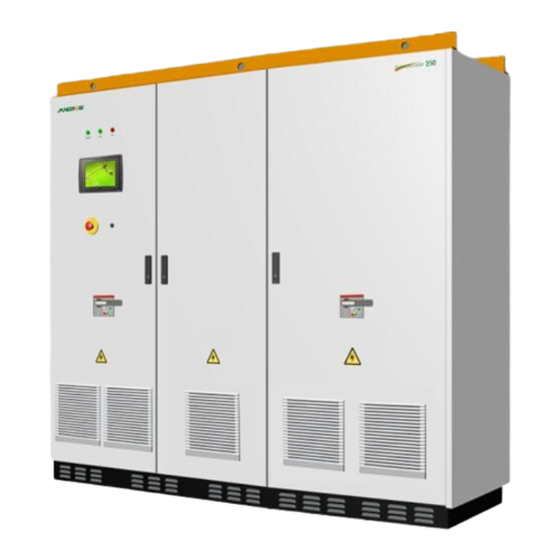
The inverter will only start when this switch is in the start position 2.3.1. The LED Indicators There are 3 large LED indicators in the SG250K3 enclosure, as can be seen in Figure 2-3; there detail explanations are listed in Table 2-2:... -
Page 17: Functions Of The Touch Screen
• Control inverter operation • Display real-time running data • Display fault data • Adjusting SG250K3 parameters • Access recorded history data 2.3.3. Emergency Stop Button The Emergency stop button will shutdown the inverter (switch off the AC contactors and stop the IPM from working) immediately when it is punched (pressed down). - Page 18 Commissioning Chapter 3 describes the verification and commissioning of SG250K3.
-
Page 19: Commissioning
3. Commissioning Chapter 3 describes the procedures needed to verify whether your installation of the SG250K3 is correct and how to start the inverter for the first time. 3.1. Visual Inspection To perform a visual inspection of theSG250K3: 1. Verify the grid circuit breaker is open. -
Page 20: Start The Inverter
3.3. How to Restart after Using the Emergency Stop Button Users must manually restart the inverter according to the following procedure when the operation of the SG250K3 is stopped by punching the emergency stop button: 1. Turn the emergency stop button clockwise to release the inverter from the stop state. - Page 21 Operation Chapter 4 provides instructions about how to operate the SG250K3.
-
Page 22: Operation
SG250K3 keeps in “Stand-by” state. If the input voltage exceeds 450V and holds the value for 1 minute, the SG250K3 is ready for operation; it begins feeding power to the grid and the state changes from “Stand-by” to “Run”. After being energized, the SG250K3 tracks the PV arrays’ maximum power point (MPP) and convert the DC power to AC power. -
Page 23: Modes Transition
4.2. Modes Transition When energized, the SG250K3 switches among different modes as pictured below. Commissionling Normal Operation Fault 1.Fault resolved for 5 minutes Fault occurs 2.Vpv>450V for 1 minutes Start-up 1. Turn the start/stop switch to start position 2. Release the emergency stop button 3. - Page 24 Data Interface Chapter 5 describes the LED indicators and touch screen data interface of SG250K3.
-
Page 25: Data Interface
5. Data Interface Users can get the running data and set parameters of SG250K3 from the LED indicators and touch screen control panel, see Figure 5-1. Figure 5-1 SG250K3 data interface 5.1. LED Indicators 3 big LED indicators are located in the front door of SG250K3. -
Page 26: Touch Screen Control Panel
5.2. Touch Screen Control Panel The touch screen control panel is mounted on the SG250K3 enclosure at eye level. Users can just touch the according function button symbols to conduct all the control or data monitoring tasks. 6 buttons right next to the touch screen are used to check or set parameters in the touch screen control menu, see Figure 5-2. - Page 27 Touch screen Menu Chapter 6 gives the detail information and explanations about the SG250K3 touch screen control menu.
-
Page 28: Touch Screen Control Menu
Chapter 6 gives the detail information and explanations about the SG250K3 touch screen control menu. SG250K3 has a big szie touch screen, which is more convenient for customers to operate directly,it has 3 main press buttons to operate on the main menu, 【Control】... -
Page 29: Default Menu (Main Window)
6.1. Default Menu (Main Window) Initialization window, Appeared only when the PV inverter is activated; Default Menu (Main Window); Display the overall information. Once the touch screen is initialized for about 2-3 minutes, it will automatically changes to the default menu. In the default menu, the basic real-time running values are displayed, which includes DC current and DC voltage, the AC phase current and AC line-to-line voltage, the operation state, the output AC power ,the total generated energy-“E-total”... -
Page 30: Start The Inverter
6.2. Start the Inverter In the Default Menu, click on the button 【Control】, get the popup window as below; Click on the button “Start” to get the window as below; Inverter by pressing “Enter” press “Cancel” to original status;... - Page 31 NOTICE: Start You can also Start/Stop the Inverter by clicking on the button 【Function】 to select “Start/Stop” sub menu.
-
Page 32: Stop The Inverter
6.3. Stop the Inverter In the Defult menu, click on the Button 【Control】, get the popup window as left; Click on the button “Stop” to get the window as left; Click on the button “Stop” To get the window as left; Press “Enter”... - Page 33 NOTICE: Start Window You can also Start/Stop the Inverter by clicking on the button 【Function】 to select “Start/Stop” sub menu. Note Manual stop and Emergency stop To the inverter, the emergency stop button has the same effect as the manual stop function.
-
Page 34: Check Running Data
6.4. Check Running Data Click on the 【Home】 button to return to the Main Window; Click on the button 【Function】, get the menu as below; Click on the button “Run-information”, running information details with “Real Time Data”, “Power Curve”, and “E-Histogram”. Real Time Data;... - Page 35 Click on the button “Power Curve” to get the information as left; “P-today power curve” diagram shows the power generated from 6.am to 18.pm in a single day, the data updated every 3.75 seconds and the total diagram data will cleared beginning of a new day.
- Page 36 Table 2 The explanation of the data name on “Power Curve” Data name explanation Unit Temp Temperature within the enclosure ℃ h-today The Operation time of today h-total Total hours of Operation time Reduced CO2 weight Reduced...
-
Page 37: Check History Data
6.5. Check History Data Click on the 【Home】 button to return to the Main Window; Click on the button 【Function】, get the menu as below; 3. Click button “History- information”, to get the long term information, details see below; “History Events”, “History faults”, and “History data”;... - Page 38 History Events; History faults; History data.
-
Page 39: Table 6-3 Explanations Of Faults
The “His-Fault” can log the latest 100 fault records, which includes the fault name and occurred time. Table 6-1 Explanations of faults Fault type Explanations Vdc-high DC voltage is too high Vac-high Grid voltage is too high Vac-low Grid voltage is too low F-fault Grid frequency is abnormal Island... -
Page 40: Entering The Password
6.6. Entering the Password When you try to “load the default parameter setup” or “change the system parameter”, you must enter the right password. Here is an example described as follows: Click on the 【Home】 button to return to the Main Window;... - Page 41 Click on the blank space to get the popup window as below; Input the password, and then press “ENT” to confirm, if wrong number is inputted, window will popup next window; Click button “Enter” to turn back.
-
Page 42: Change Display Language
6.7. Change Display Language Click on the 【Home】 button to return to the Main Window; Click on the button 【Function】, get the menu as below; Click on the button “Set-parameter”, get the window as below after entering right passord; 10. Click on the button “Sys-parameter”... - Page 43 11. Click on the button “Language” to get the language setup window; 12. You choose “English”, “Chinese” “Spanish” entering the number “0” , “1” or “2” relatively.
-
Page 44: Change System Time
6.8. Change System Time Click on the 【Home】 button to return to the Main Window; Click on the button 【Function】, get the menu as below; Click on the button “Set-parameter”, get the window as below after entering right passord; Click on the button “Sys-parameter”... - Page 45 Click on the button “Time” to get the time setup window; choose “English”, “Chinese” “Spanish” entering the number “0” , “1” or “2” relatively.
-
Page 46: Parameters Adjustment
6.9. Parameters Adjustment 6.9.1. Generated Energy Adjustment Click on the 【Home】 button to return to the Main Window; Click on the button 【Function】, get the menu as below; Click on the button “Set-parameter”, get the window as below after entering right passord;... - Page 47 Click on the button “Sys-parameter” get the window as below; Click on the button “E-total adjust” to get the window as below; Input the differential value that the energy readings between electric meter. This generated power adjustment screen is useful in case the total-power displayed by touch screen (E-total) has...
-
Page 48: Load Default Setup
6.9.2. Load Default Setup Click on the 【Home】 button to return to the Main Window; Click on the button 【Function】, get the menu as below; Click on the button “Set-parameter”, get the window as below after entering right passord; Click on the button “Sys-parameter”... - Page 49 Click on the button “Load Default” to get the window as below; Input right password, all the log history parameters settings will return to default factory setting. The process to load default is as left.
-
Page 50: Set Running Parameters
6.9.3. Set Running Parameters Click on the 【Home】 button to return to the Main Window; Click on the button 【Function】, get the menu as below; Click on the button “Set-parameter”, get the window as below after entering right passord; Click on the button “Run-parameter”... - Page 51 Input the limit data running parameter at the “Set value”column.
-
Page 52: Protection Parameter Limit
6.9.4. Protection Parameter Limit Click on the 【Home】 button to return to the Main Window; Click on the button 【Function】, get the menu as below; Click on the button “Set-parameter”, get the window as below after entering right password; Click on the button “Pro-parameter”... - Page 53 Input the limit data protection parameter “Set value” column.
-
Page 54: Communication Parameter Setup
6.9.5. Communication Parameter Setup Click on the 【Home】 button to return to the Main Window; Click on the button 【Function】, get the menu as below; Click on the button “Set-parameter”, get the window as below after entering right passord; Click on the button “Com-parameter”... - Page 55 Input address data & Baud rate for the communi- cation parameter at “Set value” column. NOTICE: Click on the input data area to get the popup digit keyboard to enter the number you need. “Com-param” menu contains some basic communication parameters of the inverter when connected to external monitoring device through RS485 serial communication protocol.
- Page 56 Maintenance Chapter 7 describes the maintenance instructions needed to keep SG250K3 at its optimum performance.
-
Page 57: Maintenance
1. Inspection of electrical wiring connection 2. Functional test of components like breakers 3. Inspection of contact joints 4. Cleaning the interior of SG250K3 A recommended maintenance period required for SG250K3 is indicated in the Table 7-1 below. Table 7-1 Maintenance period period... - Page 58 Troubleshooting Chapter 8 gives the basic troubleshooting methods to the customer as a reference.
-
Page 59: Troubleshooting
Disconnect the AC and DC voltage and keep disconnected for 5 min. Afterwards, reconnect the DC voltage and then the AC voltage. If the power LED never light after restart, please contact Sungrow. Operation shut The inverter is not in the grid connection state. -
Page 60: Touch Screen Displayed Fault Troubleshooting
8.2. Touch Screen Displayed Fault Troubleshooting If a fault occurs, the SG250K3 will generate a message and display the message in the “state:” position. Displayed Fault description and troubleshooting Table 8-3 Fault name description troubleshooting Vdc-high Over voltage on DC Disconnect the DC input of the SG250K3. - Page 61 DSP Wait for a moment to check whether this fault will disappear, Restart the inverter to see whether this fault happens again. Please contact Sungrow if this fault happens frequently. Cntr-flt AC side contactor fault This fault is un-recoverable.
- Page 62 Appendix...
-
Page 63: Appendix A: Technical Data
9. Appendix A: Technical Data The following tables list the technical data of the SG250K3. Basic production information and performance of the SG250K3 are available from these tables. 9.1. DC Parameters Max DC Power 275KWp MPPT DC Voltage Range 450V-820V... -
Page 64: Environmental Parameters
9.5. Environmental Parameters Environmental category Indoor, conditioned Pollution Degree Wet Location Ingress Protection IP20 Ambient Temperature -20° C ~ 40° C Relative Humidity (Non condensing) <95% 9.6. Features Galvanic Isolation Type Low frequency transformer Internal Consumption in stand-by <50W Transformer losses at night Cooling Display LED and LCD... -
Page 65: Exclusion Of Liability
The content of these documents is periodically checked and revised, when necessary, please call us or check our website for the latest www.sungrow.cn information. However discrepancies cannot be excluded. No guarantee is made for the completeness of these documents. Please contact our company or distributors to get the latest version. -
Page 66: About Us
The power rating of Sungrow products covers from several hundred watt to large mega-watt systems. The pursuit of Sungrow is to help our customers acquire stable and clean power with minimum cost, maximum reliability and enhanced safety. Trademarks is a registered trademark of Sungrow Power Supply Co.,Ltd.
Need help?
Do you have a question about the SG250K3 and is the answer not in the manual?
Questions and answers