
Subscribe to Our Youtube Channel
Related Manuals for Sungrow SG250HX-US


Summary of Contents for Sungrow SG250HX-US
- Page 1 PV Grid-Connected Inverter User Manual SG250HX-US SG250HX-USPV Grid-Connected InverterUser ManualSG250HX-US-UEN-Ver17- 202202 SG250HX-US-UEN-Ver17-202202...
-
Page 3: All Rights Reserved
Software Licenses • It is prohibited to use data contained in firmware or software developed by SUNGROW, in part or in full, for commercial purposes by any means. • It is prohibited to perform reverse engineering, cracking, or any other operations that... -
Page 4: About This Manual
Please read this manual carefully before using the product and keep it properly at a place for easy access. All contents, pictures, marks, and symbols in this manual are owned by SUNGROW. No part of this document may be reprinted by the non-internal staff of SUNGROW without written authorization. - Page 5 Indicates high-risk potential hazards that, if not avoided, may lead to death or seri- ous injury. Indicates moderate-risk potential hazards that, if not avoided, may lead to death or serious injury. Indicates low-risk potential hazards that, if not avoided, may lead to minor or mod- erate injury.
-
Page 7: Table Of Contents
Contents All Rights Reserved .....................I About This Manual......................II 1 Safety .........................1 1.1 Unpacking and Inspection ................1 1.2 Installation Safety ...................1 1.3 Electrical Connection Safety................2 1.4 Operation Safety ....................3 1.5 Maintenance Safety ..................4 1.6 Disposal Safety ....................4 2 Product Description ..................5 2.1 System Introduction ..................5 2.2 Product Introduction..................6 2.3 Symbols on the Product ..................8... - Page 8 4.5.1 PV Bracket-Mounted Installation ............23 4.5.2 Wall-Mounted Installation..............24 4.6 Installing the Inverter..................25 5 Electrical Connection ..................27 5.1 Safety Instructions ..................27 5.2 Terminal Description ..................28 5.3 Electrical Connection Overview ..............29 5.4 Crimp OT / DT terminal .................31 5.5 External Grounding Connection ..............32 5.5.1 External Grounding Requirements............33 5.5.2 Connection Procedure.................33 5.6 Opening the Wiring Compartment ..............33...
- Page 9 7.3 Function Overview..................58 7.4 Login ......................58 7.4.1 Requirements ..................58 7.4.2 Login Procedure .................58 7.5 Home page ....................61 7.6 Run Information....................63 7.7 Records .......................65 7.8 More......................67 7.8.1 System Parameters................67 7.8.2 Operation Parameters .................68 7.8.3 Power Regulation Parameters..............69 7.8.4 Communication Parameters..............74 7.8.5 Firmware Update ................75 7.8.6 Password Changing ................77 8 System Decommissioning ................78...
-
Page 11: Safety
Perform operations considering ac- tual onsite conditions. • SUNGROW shall not be held liable for any damage caused by violation of gen- eral safety operation requirements, general safety standards, or any safety in- struction in this manual. -
Page 12: Electrical Connection Safety
1 Safety User Manual Improper installation may cause personal injury! • If the product supports hoisting transport and is hoisted by hoisting tools, no one is allowed to stay under the product. • When moving the product, be aware of the product weight and keep the balance to prevent it from tilting or falling. -
Page 13: Operation Safety
User Manual 1 Safety Damage to the product caused by incorrect wiring is not covered by the warranty. • Electrical connection must be performed by professionals. • All cables used in the PV generation system must be firmly attached, properly insulated, and adequately dimensioned. -
Page 14: Maintenance Safety
To avoid the risk of electric shock, do not perform any other maintenance opera- tions beyond this manual. If necessary, contact SUNGROW for maintenance. Oth- erwise, the losses caused is not covered by the warranty. Disposal Safety Please scrap the inverter in accordance with relevant local regulations and stand- ards to avoid property losses or casualties. -
Page 15: Product Description
Product Description System Introduction The inverter is a transformerless 3-phase PV grid-connected inverter. As an integral compo- nent in the PV power system, the inverter is designed to convert the direct current power generated from the PV modules into grid-compatible AC current and to feed the AC current into the utility grid. -
Page 16: Product Introduction
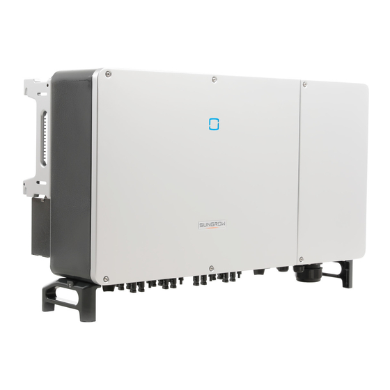
2 Product Description User Manual Make sure the inverter is applied to an IT system before enabling the Anti-PID function. Product Introduction Model Description The model description is as follows : Appearance The following figure shows the dimensions of the inverter. The image shown here is for refer- ence only. - Page 17 User Manual 2 Product Description figure 2-2 Inverter Appearance Description Name To indicate the current working state of the inverter. LED indicator Warning symbols, nameplate, and QR code. Labels External ground- 2, use to ground the inverter. ing terminals Bottom handles 2, used to move the inverter.
-
Page 18: Symbols On The Product
2 Product Description User Manual Symbols on the Product Symbol Explanation Do not dispose of the inverter together with household waste. CSA mark of conformity. CE mark of conformity. EU/EEA Importer. Danger to life due to high voltages! Only qualified personnel can open and service the inverter. Disconnect the inverter from all the external power sources before maintenance! Burn danger due to the hot surface that may exceed 60°C. -
Page 19: Circuit Diagram
User Manual 2 Product Description LED color State Definition Slow blink once, fast The inverter is performing PID recovery. blink three times A fault occurs and the device cannot connect to the grid. The Bluetooth connection is established, data commu- Twinkling nication in process, and a system fault occurs. -
Page 20: Function Description
2 Product Description User Manual • The inverter circuit converts the DC power into grid-compliant AC power and feeds it into the grid. • The AC filter filters the output AC component of high frequency to ensure that the output current meets the grid requirements. - Page 21 User Manual 2 Product Description When the anti-PID function is enabled, the inverter rises the potential of the negative pole of PV array of P-type panels to close to the ground potential through PID module to suppress PID effect. When the PID repair function is enabled, the inverter rises the potential between the nega- tive pole of PV array of P-type panels and the ground to 500Vdc through PID module, to re- pair the PID effect.
- Page 22 2 Product Description User Manual • Before enabling anti-PID function or PID repair function, make sure the voltage polarity of the PV modules to ground meets requirements. If there are any ques- tions, contact the PV module manufacturer or refer to the corresponding user manual.
-
Page 23: Unpacking And Storage
• Check the inner contents for damage after unpacking. Contact SUNGROW or the transport company in case of any damage or incompleteness, and provide photos to facilitate services. Do not dispose of the original packing case. It is recommended to store the device in the original packing case when the product is decommissioned. - Page 24 3 Unpacking and Storage User Manual • Do not place the inverter in places with items that may affect or damage the inverter. • Store the inverter in a clean and dry place to prevent dust and water vapor from eroding. •...
-
Page 25: Mechanical Mounting
Mechanical Mounting Respect all local standards and requirements during mechanical installation. Safety during Mounting Make sure there is no electrical connection before installation. Before drilling, avoid the water and electricity wiring in the wall. Poor installation environment will affect system performance! •... -
Page 26: Environment Requirements
The ambient temperature and relative humidity must meet the following requirements. • Please consult SUNGROW before installing inverters outdoors in salt stress areas. Salt stress areas mainly refer to coastal areas that are within 500 meters from the coast. The deposition of salt fog varies largely with nearby seawater characteristics, sea wind, pre- cipitation, relative humidity, terrain, and forest coverage. -
Page 27: Angle Requirements
Install the inverter vertically or at the maximum allowable rear tilt angle. Do not install the in- verter horizontally, forward, excessively backward, sideways, or upside down. Please consult SUNGROW before tilting backwards the inverter and install it in floating power plants. - Page 28 4 Mechanical Mounting User Manual * In case this distance is less than the distance in the diagram, move the inverter from the mounting-bracket or wall before maintaining fans. When the inverter is installed under the PV module whose supporting bracket is fixed, the distance between the top of the inverter and the top of the bracket can be reduced to 400mm.
-
Page 29: Installation Tools
User Manual 4 Mechanical Mounting In case of back-to-back installation, reserve specific clearance between the two inverters. Install the inverter at an appropriate height for ease of viewing LED indicator and operating switch(es). Installation Tools Installation tools include but are not limited to the following recommended ones. If necessary, use other auxiliary tools on site. -
Page 30: Moving The Inverter
4 Mechanical Mounting User Manual Rubber mallet Socket wrench set Wrench Wrist strap (16mm) (13 mm, 16 mm) Wire cutter Wire stripper Hydraulic plier Heat gun Multimeter RJ45 crimping tool MC4–Evo2 terminal MC4–Evo2 terminal crimping pliers wrench ≥ 1500 Vdc 4–6mm Vacuum cleaner Moving the Inverter... -
Page 31: Manual Transport
User Manual 4 Mechanical Mounting Improper handling may cause personal injury! • Arrange an appropriate number of personnel to carry the inverter according to its weight, and installation personnel should wear protective equipment such as anti-impact shoes and gloves. • Attention must be paid to the center of gravity of the inverter to avoid tilting dur- ing handling. -
Page 32: Installing The Mounting-Bracket
4 Mechanical Mounting User Manual step 4 Remove the lifting rings and reassemble the sealing screws released in Step 1. Keep the inverter balanced throughout the hoisting process and avoid collisions with walls or other objects. Stop hoisting in the event of severe weather, such as heavy rain, thick fog, or strong wind. -
Page 33: Pv Bracket-Mounted Installation
User Manual 4 Mechanical Mounting figure 4-1 Dimensions of mounting-bracket Install the inverter to the mounting-bracket, and dimensions after installation are as follows. 4.5.1 PV Bracket-Mounted Installation step 1 Assemble the mounting-bracket by using the connecting bar. step 2 Level the assembled mounting-bracket by using the level, and mark the positions for drilling holes on the PV bracket. -
Page 34: Wall-Mounted Installation
4 Mechanical Mounting User Manual step 3 Secure the mounting-bracket with bolts. Components Description Mounting-bracket – Full threaded bolt M10*45 – Metal bracket – Flat washer Spring washer – Hex nuts - - End 4.5.2 Wall-Mounted Installation step 1 Assemble the mounting-bracket by using the connecting bar. step 2 Level the assembled mounting-bracket by using the level, and mark the positions for drilling holes on the installation site. -
Page 35: Installing The Inverter
User Manual 4 Mechanical Mounting step 3 Insert the expansion bolts into the holes and secure them with a rubber hammer. Fasten the nut with a wrench to expand the bolt. Remove the nut, spring washer, and flat washer, and store them properly. - Page 36 4 Mechanical Mounting User Manual - - End...
-
Page 37: Electrical Connection
Electrical Connection Safety Instructions The PV string will generate lethal high voltage when exposed to sunlight. • Operators must wear proper personal protective equipment during electrical connections. • Must ensure that cables are voltage-free with a measuring instrument before touching DC cables. •... -
Page 38: Terminal Description
5 Electrical Connection User Manual • All vacant terminals must be covered with waterproof covers to prevent affect- ing the protection rating. • When the wiring is completed, seal the gap of cable inlet and outlet holes with fireproof / waterproof materials such as fireproof mud to prevent foreign matter or moisture from entering and affecting the long-term normal operation of the inverter. -
Page 39: Electrical Connection Overview
User Manual 5 Electrical Connection Item Terminal Mark Note 24, PV connector PV terminals + / - COM1 RS485 communication, digital input/output DI/ COM2 Communica- DO, and power supply of tracking system. COM3 tion terminal COM4 COM5 Reserved Opening for AC cable connection with a hole Conduit hole size of 106mm/4.17inches, suitable for con- duits of 3–1/2... - Page 40 5 Electrical Connection User Manual (A)PV string (B)Inverter (C)Grid (D)Monitoring device (E)AC circuit breaker table 5-1 Cable Requirements Specification Type Cable Cable Diame- Cross-sectional Area ter(mm) PV cable comply- DC cable ing with 1,500V 4.7~6.4 standard External Outdoor single- The same as that of the PE grounding core copper wire wire in the AC cable...
-
Page 41: Crimp Ot / Dt Terminal
User Manual 5 Electrical Connection table 5-3 Power Cable for Tracking System Specification Recommended Cable Di- Type Cable ameter Cross-sectional Area Voltage Level (mm) Power cable Double-core Consistent with se- outdoor copper 4.5~18 lected AC cable tracking cable system * Only when the cable cross-sectional area ranges between 4 mm and 6 mm , the supplied OT terminals can be used. -
Page 42: External Grounding Connection
A single grounding connection is also acceptable if it is enough to meet the requirements of local standards and re- lated safety regulations. Otherwise, SUNGROW shall not be held liable for any damage caused by the violation. -
Page 43: External Grounding Requirements
User Manual 5 Electrical Connection 5.5.1 External Grounding Requirements All non-current carrying metal parts and device enclosures in the PV power system should be grounded, for example, brackets of PV modules and inverter enclosure. When there is only one inverter in the PV system, connect the external grounding cable to a nearby grounding point. -
Page 44: Ac Cable Connection
5 Electrical Connection User Manual step 3 Keep the wiring compartment open during wiring through the limit lever attached to the cover. - - End Close the wiring compartment in reverse order after completing wiring operations. AC Cable Connection 5.7.1 AC-Side Requirements Only with the permission of the local grid department, the inverter can be con- nected to the grid. - Page 45 User Manual 5 Electrical Connection AC circuit breaker Over-current protection devices, such as AC circuit breakers and fuses, must be installed on the AC side of the inverter and the grid side to ensure safe disconnec- tion between the inverter and the grid.. •...
- Page 46 The apparent power of the inverter should never exceed the power of the transformer. The maximum AC current of all inverters connected in parallel must be taken into ac- count. If more than 15 inverters are connected to the grid, contact SUNGROW. •...
-
Page 47: Requirements For Ot/Dt Terminal
User Manual 5 Electrical Connection – Surge protective devices (SPD) for the AC combiner box and on the LV side of the transformer are recommended to be connected in the "3 +1" manner, as shown in the figure below. The Min. continuous operating voltages of M1 - M4 are 680VAC. •... - Page 48 5 Electrical Connection User Manual step 4 Remove the protection cover and store the released screws properly. step 5 Strip the protection layer and insulation layer by specific length, as described in the figure below. step 6 If wiring of tracking system power cable is required, refer to "5.9 Wiring of Tracking System Power Cable (Optional)".
- Page 49 User Manual 5 Electrical Connection Note the terminal positions of PE wire and N wire. If a phase wire is connected to the PE terminal or N terminal, unrecoverable damage may be caused to the inverter. Ensure that the depth L of the socket used is not less than 28mm. step 9 Install the protection cover.
-
Page 50: Dc Cable Connection
The damage caused by this is not covered by the warranty. • Electric arc or contactor over-temperature may occur if the PV connectors are not firmly in place, and SUNGROW shall not be held liable for any damage caused. •... -
Page 51: Assembling The Pv Connectors
User Manual 5 Electrical Connection • Each PV input area includes two DC inputs. For the best use of DC power, DC1 and DC2 should be the same in PV string structure, including the type, number, tilt, and orientation of the PV modules. Prior to connecting the inverter to PV inputs, the specifications in the following table should be met: Open-circuit Voltage Limit... - Page 52 If the cross-sectional area of the DC cable is 10mm , users need to prepare the PV connector by themselves or order it from SUNGROW. The recommended model of the female cable connector is PV-KBT4-EVO 2 / 10II-UR (Stäubli), and the recommended male cable connector is PV-KST4-EVO 2 / 10II-UR (Stäubli).
- Page 53 User Manual 5 Electrical Connection Cross-sectional area (mm Tightening torque (N∙m) step 5 Check for polarity correctness. If the PV polarity is reversed, the inverter will be in a fault or alarm state and will not operate normally. - - End Observe the specifications of the cable manufacturer with regard to the permitted bending radius.
-
Page 54: Installing The Pv Connector
5 Electrical Connection User Manual 5.8.3 Installing the PV Connector step 1 Ensure that the DC switch is in "OFF" position. Otherwise, manually turn it to "OFF". step 2 Check the cable connection of the PV string for polarity correctness and ensure that the open circuit voltage in any case does not exceed the inverter input limit of 1,500V. - Page 55 User Manual 5 Electrical Connection Outer diameter D(mm) Seal 4.5 ~ 6 6 ~ 12 a + b 12 ~ 18 step 3 Strip the protection layer and insulation layer by specific length, as described in the figure below. step 4 Install the OT terminal and press it tight. step 5 Stack the OT terminals on the OT/DT terminal of the AC cables, and fix the cables to corre- sponding terminals.
- Page 56 5 Electrical Connection User Manual Ensure that OT terminals of the power cable are installed on the OT/DT terminals of the AC cable. Otherwise, it will cause over heat or even burn. step 6 Gently pull the cable backwards to ensure firm connection, and fasten the swivel nut clockwise.
-
Page 57: Rs485 Connection
User Manual 5 Electrical Connection - - End There are four communication terminals COM1, COM2, COM3 and COM4 on the bottom of the inverter. Select the communication terminal according to onsite conditions. Disconnector (≥ 800Vac) and fuse (16A, gM) should be installed between the in- verter and the tracking system control cabinet. -
Page 58: Rs485 Communication System
5 Electrical Connection User Manual The port RS485_1 is used to connect Logger, so as to implement data exchange with PC or other monitoring devices. The port RS485_2 is used to connect communication device of the tracking system, so as to implement data exchange with the tracking system. - Page 59 User Manual 5 Electrical Connection figure 5-3 Single-inverter Connection Multi-inverter Communication System In case of multiple inverters, all the inverters can be connected via RS485 cables in the daisy chain manner. The communication cable of the tracking system can be connected to the port RS485_2 of any inverter in the daisy chain.
-
Page 60: Connection Procedure(Terminal Block)
5 Electrical Connection User Manual figure 5-5 Configuration of Dip Switch (N≥15) The length of the RS485 cable and twisted pair cable should be no longer than 1,200m. If multiple inverters are connected to the data collectorLogger3000, the number of permissible daisy chains and the number of devices allowed to be connected should meet the requirements (refer to the user manual for the Logger3000). - Page 61 User Manual 5 Electrical Connection Outer Diameter D(mm) Seal 4.5~6 6~12 12~18 step 3 Secure the cable to the terminal base. step 4 Insert the terminal base into the corresponding terminal. step 5 Pull the cable gently to make sure it is secured, tighten the swivel nut clockwise. - - End...
-
Page 62: Plc Communication Connection
User Manual 5.11 PLC Communication Connection With a built-in PLC communication module, the inverter can communicate with the CO- M100A/EMU200A (communication acquisition equipment) provided by SUNGROW. For specific wiring method, please refer to the COM100A/EMU200A user manual. • In case of PLC communication, the AC cable must be a multi-core cable in- stead of multiple single-core cables. - Page 63 User Manual 5 Electrical Connection DO terminal (fault output dry contact):the relay can be set to fault alarm output, and user can configure it to be a normal open contact (COM&NO) or a normal close contact (COM& NC). The relay is initially at the NC terminal, and it will trip to another contact when a fault occurs. Use LED indicators or other equipment to indicate whether the inverter is in the faulty state.
-
Page 64: Wiring Procedure
5 Electrical Connection User Manual figure 5-8 Local Stop Contact When wiring DI dry contacts, ensure that the maximum wiring distance meet the require- ments in "10.2 Wring Distance of DI Dry Contact". 5.12.2 Wiring Procedure Refer to the wiring of terminal block described in chapter "5.10.3 Connection Procedure(Ter- minal Block)". -
Page 65: Commissioning
Commissioning Inspection before Commissioning Check the following items before starting the inverter: • All equipment has been reliably installed. • DC switch(es) and AC circuit breaker are in the "OFF" position. • The ground cable is properly and reliably connected. •... - Page 66 6 Commissioning User Manual step 5 The home page is automatically displayed when the initialization is completed. The indicator is steady blue, and the inverter is in grid-connected operation. - - End...
-
Page 67: Isolarcloud App
iSolarCloud App Brief Introduction The iSolarCloud App can establish communication connection to the inverter via the Blue- tooth, thereby achieving near-end maintenance on the inverter. Users can use the App to view basic information, alarms, and events, set parameters, or download logs, etc. *In case the communication module Eye, WiFi or WiNet-S is available, the iSolarCloud App can also establish communication connection to the inverter via the mobile data or WiFi, thereby achieving remote maintenance on the inverter. -
Page 68: Function Overview
7 iSolarCloud App User Manual Function Overview The App provides parameter viewing and setting functions, as shown in the following figure. figure 7-1 App function tree map Login 7.4.1 Requirements The following requirements should be met: • The AC or DC side of the inverter is powered-on. •... - Page 69 User Manual 7 iSolarCloud App number on the nameplate on the side of the inverter, or tap to scan the QR code on the side of the inverter for Bluetooth connection. The connection is successfully established if the LED indicator blinks blue. figure 7-2 Bluetooth Connection step 3 Enter the identity verification screen after the Bluetooth connection is established.
- Page 70 To set inverter parameters related to grid protection and grid support, contact SUNGROW to obtain the advanced account and corresponding password. step 4 If the inverter is not initialized, you will enter the quick setting screen of initializing protection...
-
Page 71: Home Page
User Manual 7 iSolarCloud App figure 7-4 Initialization Protection Parameter The Country/Region must be set to the country where the inverter is installed at. Otherwise, the inverter may report errors. step 5 After finishing the settings, tap TUNR ON DEVICE at the upper right corner and the device will be initialized. - Page 72 7 iSolarCloud App User Manual figure 7-5 Home page table 7-1 Home Page Description Designation Description System date and time of the inverter Date and time Present operation state of the inverter For details, refer to Inverter state "table 7-2 Description of Inverter State".
-
Page 73: Run Information
User Manual 7 iSolarCloud App table 7-2 Description of Inverter State Description State After being energized, inverter tracks the PV arrays’ maximum power point (MPP) and converts the DC power into AC power. This is the nor- mal operation mode. Stop Inverter is stopped. - Page 74 7 iSolarCloud App User Manual table 7-4 Run information Classifica- Description Parameter tion String n Voltage The input voltage of the n string String n current The input current of the n string Information Total On-grid Run- ning Time Daily On-grid Run- ning Time Negative Voltage to Inverter DC side negative to ground voltage value...
-
Page 75: Records
User Manual 7 iSolarCloud App Classifica- Description Parameter tion Phase C Current Records Tap Records on the navigation bar to enter the screen showing event records, as shown in the following figure. figure 7-6 Records Fault Alarm Record Tap Fault Alarm Record to enter the screen, as shown in the following figure. figure 7-7 Fault Alarm Record Click to select a time segment and view corresponding records. - Page 76 7 iSolarCloud App User Manual figure 7-8 Detailed Fault Alarm Information Yield Record Tap Yield Record to enter the screen showing daily power generation , as shown in the fol- lowing figure. figure 7-9 Power Curve The App displays power generation records in a variety of forms, including daily power gen- eration graph, monthly power generation histogram, annual power generation histogram and total power generation histogram.
-
Page 77: More
User Manual 7 iSolarCloud App Description Parameter Monthly energy Shows the power output every month in a year. histogram Annual energy Shows the power output every year. histogram Tap the time baron the top of the screen to select a time segment and view the correspond- ing power curve. -
Page 78: Operation Parameters
7 iSolarCloud App User Manual figure 7-11 System Parameters * The image shown here is for reference only. Boot/Shutdown Tap Boot/Shutdown to send the boot/shutdown instruction to the inverter. Date Setting/Time Setting The correct system time is very important. Wrong system time will directly affect the data logging and power generation value. -
Page 79: Power Regulation Parameters
User Manual 7 iSolarCloud App figure 7-13 PID Setting table 7-6 PID Parameter Description Description Parameter Set enabling/disabling of the PID night recovery function. PID night PID repair recovery functions between 22:00 pm and 5:00 am by default. Enable this function of the inverter to protect PV modules from PID PID protection effect during the daytime If ISO impedance abnormality or PID function exception is de-... - Page 80 7 iSolarCloud App User Manual figure 7-15 Active Power Regulation table 7-7 Active Power Regulation Definition/Setting Range Parameter Description Active power soft start The switch for enabling/dis- Enable/Disable after fault abling the soft start function after a fault occurs. Active power soft start Time that the soft start takes to 1s~1200s time after fault...
- Page 81 User Manual 7 iSolarCloud App Definition/Setting Range Parameter Description Active power limit ratio The ratio of limiting output 0%~100% power to rated power in percentage. Shutdown when active Switch used to determine Enable/Disable power limit to 0% whether the inverter is in stop state when the limited power reaches 0.
- Page 82 7 iSolarCloud App User Manual Definition/Setting Range Parameter Description Reactive power regula- Ends time of reactive 0.1s~600.0s tion time response. Q(P)Curve Select the corresponding Curve A/Curve B/Curve C* curve according to local regulations QP_P1 Output power at P1 on the Q 0.0%~100.0% (P) mode curve (in percentage)
- Page 83 User Manual 7 iSolarCloud App Definition/Setting Range Parameter Description Q(U)Curve Select the corresponding Curve A/Curve B/Curve C* curve according to local regulations QU_V1 Pre-set grid voltage U1 that is 80.0%~100.0% reactive according to the grid voltage QU_Q1 Pre-set proportion of reactive [-60.0%-0]* Overload Rate/ power according to the grid 1000...
-
Page 84: Communication Parameters
7 iSolarCloud App User Manual **Curve C is reserved and consistent with Curve A currently. figure 7-17 Q(U) Curve figure 7-18 Q(P) Curve 7.8.4 Communication Parameters Tap Settings→Communication Parameters→Serial Port Parameters to enter the corre- sponding interface, as shown in the following figure. figure 7-19 Serial Port Parameters table 7-9 Serial Port Parameters Range... -
Page 85: Firmware Update
User Manual 7 iSolarCloud App figure 7-20 MPLC Parameters table 7-10 MPLC Parameters Range Parameter Band Num Band1, Band2 Array ID 1–255 Winding ID 1–10 7.8.5 Firmware Update To avoid download failure due to poor on-site network signal, it is recommended to download the firmware package to the mobile device in advance. - Page 86 7 iSolarCloud App User Manual figure 7-21 Firmware Download step 3 Select the firmware from the file list and download. Tap Downloaded to view successfully downloaded firmware package. figure 7-22 Downloading Firmware Package step 4 Login the App via local access mode. Refer to "7.4 Login".
-
Page 87: Password Changing
User Manual 7 iSolarCloud App 7.8.6 Password Changing Tap Modify Password to enter the modify password screen, as shown in the following figure. figure 7-24 Change Password The password shall consisit of 8–20 digits, including letters and numbers. -
Page 88: System Decommissioning
System Decommissioning Disconnecting the Inverter Danger of burns! Even if the inverter is shut down, it may still be hot and cause burns. Wear protec- tive gloves before operating the inverter after it cools down. For maintenance or other service work, the inverter must be switched off. Proceed as follows to disconnect the inverter from the AC and DC power sources. -
Page 89: Disposal Of The Inverter
User Manual 8 System Decommissioning step 2 Refer to"4 Mechanical Mounting", to dismantle the inverter in reverse steps. step 3 If necessary, remove the wall-mounting bracket from the wall. step 4 If the inverter will be used again in the future, please refer to "3.2 Inverter Storage"... -
Page 90: Troubleshooting And Maintenance
App or the LCD. Modify the overvoltage protection values with the con- sent of the local electric power operator. 3. Contact Sungrow Customer Service if the pre- ceding causes are ruled out and the fault persists. Generally, the inverter will be reconnected to the grid after the grid returns to normal. - Page 91 2. Check whether the protection parameters are appropriately set via the App or the LCD. 3. Contact Sungrow Customer Service if the pre- ceding causes are ruled out and the fault persists. Generally, the inverter will be reconnected to the grid after the grid returns to normal.
- Page 92 App or the LCD. 3. Contact Sungrow Customer Service if the pre- ceding causes are ruled out and the fault persists. 1. Check whether the corresponding string is of reverse polarity.
- Page 93 3. Check if the DC fuse is damaged. If so, replace Alarm the fuse. 4. Contact Sungrow Customer Service if the pre- ceding causes are ruled out and the alarm persists. *The code 548 to code 563 are corresponding to string 1 to string 16 respectively.
- Page 94 3. If the cable is normal and the fault occurs on rainy days, check it again when the weather turns fine. 4. Contact Sungrow Customer Service if the pre- ceding causes are ruled out and the fault persists. 1. Check whether the AC cable is correctly connected.
- Page 95 2. Reconnect the communication cable of the cation Abnormal meter. Alarm 3. Contact Sungrow Customer Service if the pre- ceding causes are ruled out and the alarm persists. 1. Check whether the output port is connected to actual grid. Disconnect it from the grid if so.
- Page 96 0.5 A. MPPT Reverse 264-283 2. Contact Sungrow Customer Service if the pre- Connection ceding causes are ruled out and the fault persists. *The code 264 to code 279 are corresponding to string 1 to string 20 respectively.
- Page 97 DC current is greater than 0.5A when the fault occurs. System Hardware 1616 2. Disconnect the DC switch only when the inver- Fault ter DC side current drops below 0.5A. 3. It is prohibited to power up the inverter again. Please contact Sungrow Customer Service.
-
Page 98: Maintenance
To avoid the risk of electric shock, do not perform any other maintenance opera- tions beyond this manual. If necessary, contact SUNGROW for maintenance. Oth- erwise, the losses caused is not covered by the warranty. -
Page 99: Routine Maintenance
User Manual 9 Troubleshooting and Maintenance 9.2.2 Routine Maintenance Item Method Period Check the temperature and dust of the inverter. Clean the inverter enclo- Six months to a year (de- sure if necessary. System clean pend on the dust contents Check if the air inlet and outlet are in air.) normal. - Page 100 9 Troubleshooting and Maintenance User Manual Fans inside the inverter are used to cool the inverter during operation. If the fans do not op- erate normally, the inverter may not be cooled down and inverter efficiency may decrease. Therefore, it is necessary to clean dirty fans and replace the broken fans in a timely manner. The operation procedure is as follows: step 1 Stop the inverter (see "8.1 Disconnecting the...
- Page 101 User Manual 9 Troubleshooting and Maintenance step 4 Pull out the fans, four on the left side and one on the right side. Clean them with a soft brush or vacuum cleaner, and replace them when necessary. step 5 Reinstall the fan back to the inverter in reverse order and restart the inverter. - - End...
-
Page 102: Appendix
10 Appendix 10.1 Technical Data SG250HX-US Parameters Input (DC) Max. PV input voltage 1500V Min.PV input voltage/Startup in- 500V / 500V put voltage Nominal input voltage 1080V MPP voltage range 500V~1500V MPP voltage range for nominal 860V~1300V power No. of independent MPP inputs Max. -
Page 103: Wring Distance Of Di Dry Contact
User Manual 10 Appendix SG250HX-US Parameters AC short-circuit protection Leakage current protection Grid monitoring Ground fault monitoring DC switch AC switch Arc fault circuit interrupter (AFCI) PV string current monitoring Reactive power at night function Anti-PID or PID recovery PID protection... - Page 104 10 Appendix User Manual refers to the cable length in one direction between the DI dry contact terminal of the k verter and the corresponding terminal of the (k-1) inverter. table 10-1 Correspondence between number of inverters and maximum wiring distance Maximum wiring distance(unit:m) Number of inverter...
-
Page 105: Quality Assurance
• The customer shall give SUNGROW a reasonable period to repair the faulty device. Exclusion of Liability In the following circumstances, SUNGROW has the right to refuse to honor the quality guarantee: • The free warranty period for the whole machine/components has expired. - Page 106 10 Appendix User Manual We need the following information to provide you the best assistance: • Model of the device • Serial number of the device • Fault code/name • Brief description of the problem For detailed contact information, please visit: https://en.sungrowpower.com/contactUS.
Need help?
Do you have a question about the SG250HX-US and is the answer not in the manual?
Questions and answers