Table of Contents
Advertisement
Quick Links
Advertisement
Table of Contents
Troubleshooting

Related Manuals for Sungrow SG2500U-MV


Summary of Contents for Sungrow SG2500U-MV
- Page 1 SG2500U-MV MV Turnkey Station System Manual SG2500U-MV-V11-SEN-Ver10-201805...
-
Page 3: Table Of Contents
Contents About This Manual ..............1 1.1 Preface ......................1 1.2 Validity ......................1 1.3 Content ......................1 1.4 Target Group....................1 1.5 Symbols Explanation ................... 2 1.6 How to Use this Manual ................3 1.7 Terminology ....................3 Safety Instructions ..............4 2.1 Intended Usage ................... - Page 4 3.3 Overall Design of the MV Station .............. 11 3.3.1 MV Station Views ................11 3.3.2 Mechanical Parameter ..............13 3.3.3 Ventilation Design ................14 3.4 Interior Design of the MV Station .............. 14 3.4.1 Internal Components ................ 14 3.4.2 Cable Entry Design ................15 3.4.3 Internal Devices of the MV Station ...........
- Page 5 6.4.4 Removing Sealing Tapes of Cable Inlet holes ........32 6.4.5 Checking the Cables ................. 32 6.4.6 During Connection ................33 6.5 MV Station Circuit Diagram and Cable Connection ........33 6.5.1 Circuit Diagram ................. 33 6.5.2 Cable Specifications ................33 6.6 General principles for cable connections ..........
- Page 6 8.2.1 Normal Stop ..................48 8.2.2 MV Station Stops when A Fault Occurs ..........48 LCD Menu Operation ............. 49 9.1 LCD Touch Screen ................... 49 9.2 Default Screen ..................49 9.2.1 Initialization..................49 9.2.2 Default Screen Introduction .............. 49 9.2.3 Backlight and Screensaver ..............
- Page 7 10.3.2 How to Realize Power Limitation ............ 68 10.4 Reactive Power Adjustment ............. 69 10.5 L/HVRT .................... 70 10.6 Temperature Derating ..............71 10.7 MPPT ....................71 10.8 Intelligent Temperature-Control Technology ........72 10.9 Insulation Monitoring Function............72 10.9.1 Introduction ..................72 10.9.2 Simple Troubleshooting ..............
- Page 8 12.2.3 Filter checking and cleaning............87 12.2.4 Cleaning MV Station Air Inlet Window ..........88 12.2.5 Replacement of the electrical components ........89 12.3 On-site painting make-up measures ..........89 12.4 Replacement of the electrical components ........93 13 Appendix ................94 13.1 MV Station System Parameter............
-
Page 9: About This Manual
1.2 Validity This manual is applicable to the MV Turnkey Station product of SG2500U-MV (hereinafter it will be referred to as "MV Station" unless otherwise specified). 1.3 Content... -
Page 10: Symbols Explanation
1 About This Manual System Manual Equipped with the ability to cope with the dangerous and emergency situations during installation and commissioning Familiar with the country/regional standards and specifications Familiar with this manual 1.5 Symbols Explanation This manual contains important safety and operational instructions that must be accurately understood and respected during the installation and maintenance of the equipment. -
Page 11: How To Use This Manual
All rights reserved including the pictures, markings and symbols used. Any reproduction or disclosure, even partially, of the contents of this manual is strictly forbidden without prior written authorization of Sungrow. The contents of the manual will be periodically updated or revised due to the product development. -
Page 12: Safety Instructions
2 Safety Instructions 2.1 Intended Usage The MV Station, R & D and manufactured by Sungrow, is mainly applied to large-and-medium PV power station. The MV Station integrates the DC cabinet, module cabinet, medium voltage transformer, monitoring & power distribution units, firefighting system, lighting devices, and security &... -
Page 13: General Safety Rules
System Manual 2 Safety Instructions 2.2.1 General Safety Rules Touching the terminals or contactors connected to the grid may lead to electric shock hazards! Do not touch the terminals or conductors connected to the grid. Respect all safety instructions on the grid connection. Lethal voltages are present inside the device! ... -
Page 14: Ground Fault Protection
2 Safety Instructions System Manual MV Station is disconnected from the PV array. Necessary warning signs are in place to prevent accidental reconnection. 2.2.4 Ground Fault Protection If a ground fault occurs in the PV system, some parts that were voltage-free before may contain lethal voltage. -
Page 15: Esd Protection
System Manual 2 Safety Instructions 2.2.8 ESD Protection Devices may be damaged irreversibly by electrostatic discharge (ESD). Avoid unnecessary touching of the PCB. Observe all the ESD-related safety instructions. Take proper personal protective equipment (PPE), like wear wrist strap. 2.2.9 LCD Parameter Setting Certain LCD settable parameters are closely related to the MV Station and internal devices operation, therefore these parameters can only be set after reliable evaluation of the... -
Page 16: Disposal Of Waste
This manual may not cover all possible situations. Should a specific problem occur that is not explained in this manual, please contact Sungrow. 2.3 Safety Instructions of Each Working Area The MV Station can be divided into MV Station room, and transformer room. To make sure the device safety and efficient operation, the abovementioned two parts are designed relatively independently. -
Page 17: Safe Operation Of The Mv Station Room
System Manual 2 Safety Instructions 2.3.1 Safe Operation of the MV Station room Perform the operations in this section before any operation on the MV Station room. Physical injury or device damage may follow if otherwise. Step 1 Identify the MV Station and read the safety instructions on the MV Station cabinet carefully. Step 2 Disconnect all power supplies from the MV Station, including MV Station upstream and downstream devices and other connected power supplies. -
Page 18: Product Description
3 Product Description 3.1 Brief Introduction The MV Station mainly applies to medium and large-scale PV generation systems. Based on standard-sized outdoor container, the MV Station integrates DC cabinet, module cabinet, transformer, security system and firefighting equipment to meet with the requirements of modular design and fast installation of the PV systems. -
Page 19: Overall Design Of The Mv Station
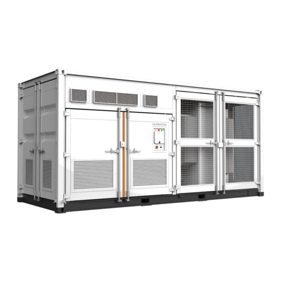
System Manual 3 Product Description 3.3 Overall Design of the MV Station 3.3.1 MV Station Views View Description Front view. „A‟ is the LCD protective box. Back view. Left view. Right view. - Page 20 3 Product Description System Manual Control and Monitoring Window The Control and Monitoring window is located on the front door. On the top is the LED indicator; in the middle is the color liquid crystal touch screen and on the bottom are the emergency stop button, the “AC” knob switch, the “DC” knob switch, “AUX SUPPLY”...
-
Page 21: Mechanical Parameter
System Manual 3 Product Description 3.3.2 Mechanical Parameter Dimensions External dimensions (without the flashings) are shown in the figure below. Height Width Depth Fig. 3-2 Appearance and dimensions of the MV Station Width Height Depth 6058mm 2896mm 2438mm The Clearance Spaces The clearance spaces around the MV Station should be sufficient for the doors all opened. -
Page 22: Ventilation Design
3 Product Description System Manual 3.3.3 Ventilation Design Six air intake grills (In-1, In-2, and In-3 in the figure below), located in the MV Station room, are the entries of fresh air. Exhaust air of the MV Station is extracted via Out-1, and Out-2. Out-1 In-2 In-1... -
Page 23: Cable Entry Design
System Manual 3 Product Description 3.4.2 Cable Entry Design For convenient cable connection in the field, all cables among the MV Station internal devices are connected before delivery. All cables between the MV Station and the external are routed through the bottom of the MV Station. -
Page 24: Internal Devices Of The Mv Station
3 Product Description System Manual 3.4.3 Internal Devices of the MV Station DC cabinet DC connection areas are in this cabinet, as shown in the figure below. Item Description DC+ input copper bar input copper bar Intelligent PMD The ports between the MV Station and external devices are designed on this cabinet. The locations of the ports are shown in the following figure. -
Page 25: Operations On The Dc Circuit Breakers
System Manual 3 Product Description 3.4.4 Operations on the DC circuit breakers The MV Station is equipped with electrically-controlled air circuit breakers on the DC side. The appearance of the circuit breaker panel is shown in the figure below. DISCHARGED CLOSED SPRING Push ON... -
Page 26: Identify And Store The Mv Station
Therefore, once you receive the MV Station, a detailed inspection is necessary. If any damage is detected, contact the shipping company or Sungrow immediately. A relevant photo is preferred. We will provide you with the fast and best service. - Page 27 User Manual 4. Identify and Store the MV Station Relative humidity: 0 ~ 95%, non-condensation Store the MV Station in a dry, clean and solid ground with sufficient load capacity. The ground should be flat without water, bumps or plantings. ...
-
Page 28: Mechanical Installation
Mechanical Installation Respect all local standards and requirements during mechanical installation. 5.1 Transport All devices are installed inside the MV Station before delivery. The MV Station should be transported as a whole. Transport the MV Station by crane with sufficient load capacity. The MV Station is delivered to the user by a forwarding company. -
Page 29: Hoisting The Mv Station
System Manual 5 Mechanical Installation 5.2 Hoisting the MV Station 5.2.1 Safety Precautions Observe the safety operating rules of the crane at all times. Standing within 5 to 10 meters of the hoisting areas is strictly forbidden! Anybody standing under the boom or MV Station is strictly forbidden in the whole hoisting process. -
Page 30: Hoisting
5 Mechanical Installation System Manual 5.2.2 Hoisting In the whole hoisting process, please observe following rules: Hoist the MV Station in a vertical manner. Do not drag or drop the MV Station on any surface. When the MV Station has been hoisted for about 300mm from the ground, stop to check if all the connections are still firm. -
Page 31: Fastening Of Connectors
National and local safety rules should be observed at all times. Regardless of relevant safety rules may void pertinent warranty claims from Sungrow. 5.3 Foundation 5.3.1 Selection of Installation Site When selecting the installation site, consider at least the following requirements: ... -
Page 32: Recommended Foundation Construction Plan
5 Mechanical Installation System Manual designed and constructed according to related standard. The dimensions, weight of the MV Station, the cable route and later maintenance should be considered at all times. The following conditions must be fulfilled: The bottom of foundation should be firm enough. ... - Page 33 System Manual 5 Mechanical Installation 2179mm 1700mm 2179mm Refer to the above distances to construct the foundation. >400 Item Name Note Foundation Pea gravel ground Pre-embedded 20# channel steel H*W*S=200*75*90mm...
-
Page 34: Other Precautions
5 Mechanical Installation System Manual The foundation plan described in this chapter is for reference only; please consult on-site professional project personnel before project construction. 20# channel steel is pre-embedded on the front and back side of the foundation surface so that the foundation of MV Station can be welded with the foundation after the mechanical installation. -
Page 35: Removing Flashings And Cover Plates
System Manual 5 Mechanical Installation 5.4 Removing Flashings and Cover Plates The flashings and cover plates are attached to the enclosure of the MV Station to prevent moisture penetration during transportation. Locations of the flashings and cover plates are shown by A and B respectively in the figure below. Remove the flashings and cover plates before commissioning. -
Page 36: Electrical Installation
Electrical Installation 6.1 Safety Instructions 6.1.1 Generals rules High voltage! Electrical hazards! Do not touch the live components of the device. Make sure the AC and DC sides are voltage-free before installation. Never put flammable materials in the vicinity of the module. If a ground fault occurs in the PV system, some parts that were voltage-free before may contain lethal voltage. -
Page 37: Five Safety Rules
The installation and design of the MV Station must fulfill national and local standards and regulations. Sungrow should hold no liability for the MV Station or system fault caused by ignorance of the description in this manual. Select optical fibers as the external communication cable to lower the signal interference. -
Page 38: Parts For Cabling
6 Electrical Installation System Manual Verify that no voltage or current is present with appropriate testing devices. Ground and short-circuit whenever necessary. Cover possible live parts to avoid accidental contact. 6.2 Parts for Cabling Incorrect connection of power cables will cause fires. Follow the sequence when connecting the power cables. -
Page 39: Aluminum Wire Connection
System Manual 6 Electrical Installation 6.2.2 Aluminum Wire Connection When the aluminum wire is selected, a copper-aluminum bi-metallic lug is needed as shown below: Fig. 6-2 Albronze filter connection Copper Bus copper-aluminum bi-metallic lug Bolt Spring washer Flat washer Aluminum cable connections for the transformer please refer to transformer manual. -
Page 40: Installation Tools
6 Electrical Installation System Manual 6.4.1 Installation Tools Prepare the following tools before installation: Torque wrench Screwdriver Wire stripper Terminal crimping device Alcohol blast burner (or hot air blower) Allen wrench Meg-ohmmeter or multimeter ... -
Page 41: During Connection
System Manual 6 Electrical Installation 6.4.6 During Connection Make sure the DC cables and AC cables are correctly routed before connection. Do not pull the cables hard during connection. Make sure there is enough wire bending space for all connection cables. ... -
Page 42: General Principles For Cable Connections
6 Electrical Installation System Manual Cables for one polarity or phase should be of the same type and specification. Flame retardant and fire resistant cables are recommended. Overloading operation of cables is strictly forbidden. 6.6 General principles for cable connections Based on the cable entries design on the bottom of the MV Station, cables inside and outside the MV Station should be laid between the MV Station base and MV Station bottom. - Page 43 System Manual 6 Electrical Installation 6x95 6x95 6x95 44.5 44.5 44.5 6x50 6x50 6x50 247.75 73 173.66 83.5 Front view of DC cabinet Side view of DC cabinet Cable requirements: 21 input cables can be connected to the DC side ...
-
Page 44: Ac Connection
6 Electrical Installation System Manual Step 4 Insert the heat-shrinkable tubing; A tubing with length 2cm longer than the depth of the cable lug is recommended; Insert the heat-shrinkable tubing into the cable lug; Shrink the tubing with a hot air blower. Cable protectors are advisable in the cable crosses if the multi-core cables are used. -
Page 45: Ac Cable Connection
System Manual 6 Electrical Installation Electrical hazards! Do not touch the live components. Disconnect the AC switches and ensure all terminals are voltage-free. The connection to the public grid must be carried out only after receiving approval from the distribution utility as required by national and state interconnection regulations. -
Page 46: External Grounding
6 Electrical Installation System Manual 6x50 13x50 All devices inside the MV Station should be connected equipotentially. The connection of the MV Station main electrical devices to the ground copper bar has been finished before delivery. Please perform the following operation on-site: ... -
Page 47: Communication Connection
System Manual 6 Electrical Installation Perform the external grounding according to the on-site conditions and instructions from the plant staff. The following two methods are recommended to fix the grounding flat steel to the external grounding points of the Station: ... -
Page 48: External Power Supply Connection
6 Electrical Installation System Manual 6.11 External Power Supply Connection The location of external power supply port of the MV Station is shown in the following figure. On site, perform cable connection according to port definition. Item Description External power supply micro breaker Grounding copper bar (for N wire) The wiring diagram of external power supply The wiring diagram of external power supply is shown in the figure below. -
Page 49: Finishing Electrical Connection
System Manual 6 Electrical Installation 6.12 Finishing Electrical Connection After the electrical connection, check the connection of all cables. Make sure all connections are correct and firm. After checking that all connections are correct and firm, Tighten all the cable entries. ... -
Page 50: Commissioning
7 Commissioning 7.1 Safety Instructions High voltage! Electric shock! Wear proper protection equipment before all operations on the device. Do not touch the live terminals or conductors. Respect all safety instructions inside the device and in this manual. ... -
Page 51: Checking Before Commissioning
System Manual 7 Commissioning Ensure the system is properly grounded. Ground resistance is important for the whole system so that before commissioning, make sure the ground resistance is less than 4Ω NOTICE All operation during commissioning must be performed by qualified personnel only. -
Page 52: Checking Grid Voltage
7 Commissioning System Manual may be damaged. Make sure the environmental condition is stable since the voltage of PV array may change with the solar radiation and the temperature of the PV cells. Use the U-I curve to record the PV array situation. -
Page 53: Lcd Parameter Setting
System Manual 7 Commissioning Step 4 Stop the MV Station through the touch screen. Turn off the “Trip Enable”, and turn off the “Door-protect enable” through the screen. Step 5 Turn the “AC” knob switch to the ON position and manually close the two AC switches Step 6 inside the MV Station to wait the MV Station to display the key off state. - Page 54 7 Commissioning System Manual MV Station needs no manual control in daily operation. Open the cabinet door only for maintenance or troubleshooting and by qualified personnel only. Keep the door closed and locked and store the keys of the door by appointed personnel during normal operation.
-
Page 55: Starting/Stopping
8 Starting/Stopping 8.1 Starting 8.1.1 Inspection before starting After the maintenance or service work, you may start the MV Station. Inspect the following requirement before starting the MV Station: All connections are done by strictly following the relevant manual and circuit diagram. ... -
Page 56: Stopping
7 Starting/Stopping System Manual MV Station needs no manual control in daily operation. Open the cabinet door only for maintenance or troubleshooting and by qualified personnel only. Keep the door closed and locked and store the keys of the door by appointed personnel during normal operation. -
Page 57: Lcd Menu Operation
9 LCD Menu Operation 9.1 LCD Touch Screen The LCD touch screen, located at the eye-level inside the monitoring window on the front side of the MV Station is used for user to view the data and set related parameters. For user‟s convenience, there are a large number of pictures about the LCD interface in this chapter. -
Page 58: Backlight And Screensaver
Do not modify any parameters before you fully understand this manual or consult the staff from Sungrow. 9.2.3 Backlight and Screensaver If there is no operation to the screen for more than 5 minutes, the backlight will be off. -
Page 59: Entering Password
System Manual 9 LCD Menu Operation Item Description Title bar The first line from the top is the present success rate of communication. The left side of the second line is the name of the present page, while the right side is the present date and time. -
Page 60: Language Setting
9 LCD Menu Operation System Manual If the input password is 1111, user can enter into the normal parameter setting page and set the system parameters, running parameters, protection parameters and communication parameters. Press “Enter” to confirm the password input. Step 5 If the password is incorrect, an “Error password”... -
Page 61: Date And Time Setting
System Manual 9 LCD Menu Operation 9.6 Date and Time Setting Tap “Function” from the default menu; Step 1 Tap “Set-parameter”; Step 2 Tap “Sys-parameter” after entering the correct password; Step 3 Tap “Time” and enter into the date and time setting sub-menu; Step 4 Set the “Year”, “Month”, “Date”, “Hour”, “Minute”... -
Page 62: History Information Checking
9 LCD Menu Operation System Manual E-histogram The power yields of the present day in histogram. Proceed as follow to view the running information: Tap “Function” from the default menu; Step 1 Tap “Run-information” and switch among “Real Time Data”, “Power curve” and Step 2 “E-histogram”. -
Page 63: History Data Checking
System Manual 9 LCD Menu Operation Up to 100 history events can be viewed from this sub-menu, with up to 5 records can be shown on one page. The upper left side of the event table is the total number of the current event records. -
Page 64: History Alarm Checking
9 LCD Menu Operation System Manual 9.8.4 History Alarm Checking Proceed as follows to check the history warn information: Tap “Function” from the default menu; Step 1 Tap “History-information” and enter into the history information sub-menu; Step 2 Tap “his-alarm” and enter into the history alarm sub-menu. Step 3 Up to 100 history alarms can be viewed from this sub-menu, with up to 5 records can be shown on one page. -
Page 65: Starting/Stopping
System Manual 9 LCD Menu Operation 9.10 Starting/Stopping Usually, the MV Station will start automatically when the grid-connected requirements are met. Follow either of the two ways below to start/stop the MV Station through the LCD screen: Tap “Start/Stop” from the default menu. ... -
Page 66: Parameters Of Lcd
9 LCD Menu Operation System Manual Tap “Language & Firmware Ver.” and enter into the language and firmware version Step 4 sub-menu; The firmware version of LCD and DSP is shown at the bottom of the page. Step 5 9.13 Parameters of LCD 9.13.1 Communication Parameters Improper communication parameter configuration may lead to communication... -
Page 67: Running Parameters
System Manual 9 LCD Menu Operation Two parameters pertinent to RS485 serial port communication can be set according to the parameter range shown on the display. “Address” is prescribed by the plant staff and the address for each device must be unique when there is more than one device. - Page 68 9 LCD Menu Operation System Manual Description of Running Parameters Parameter Description Vmppt-max (V) Maximum MPPT voltage Vmppt-min (V) Minimum MPPT voltage T-start-wait (s) The time from the AC/DC parameters meet the grid-connection conditions to the MV Station begins to generate power. T-stop-delay (s) The time from the LCD display or upper computer sends stop command to MV Station performs the stop command...
-
Page 69: Protection Parameter
System Manual 9 LCD Menu Operation Running parameter range and default value are shown in the following table. Parameter Range Default Vmppt-max (V) 800~1300 1300 Vmppt-min (V) 800~1300 T-start-wait (s) 0~600 T-stop-delay (s) 0~600 stop slope (%/s) 0.1~100 Limit Power (%) 0~110 -0.8~-1/0.8~1 Q-limit (%) - Page 70 9 LCD Menu Operation System Manual Description of Protection Parameters Parameter Description Set the grid over-voltage protection Ⅰ value. Protection is Ⅰ_Vgrid-max(%) activated when voltage exceeds this value. Set the grid over-voltage protection Ⅱ value. Protection is Ⅱ_Vgrid-max(%) activated when voltage exceeds this value. Set the grid over-voltage protection Ⅲ...
- Page 71 System Manual 9 LCD Menu Operation Parameter Description Ⅱ_T-Fhigh trip (ms) Set the grid over-frequency II tripping time Ⅲ_T-Fhigh trip(ms) Set the grid over-frequency Ⅲ tripping time Ⅳ_T-Fhigh trip (ms) Set the grid over-frequency Ⅳ tripping time Ⅴ_T-Fhigh trip(ms) Set the grid over-frequencyⅤ tripping time Set the grid under-frequency protection I value.
- Page 72 9 LCD Menu Operation System Manual Parameter Description Grid_V-unbalanced protect 3-phase grid voltage unbalance protection threshold value value(%) Grid_V-unbalanced protect 3-phase grid voltage unbalance time reaches to the set value. time(S) Protection is activated monitor measure Insulation monitoring time time(S) monitor protect Insulation monitoring protection threshold value...
- Page 73 Improper parameter configuration may affect the normal operation of the MV Station! Only authorized personnel can configure these parameters. Should any question or doubt occurs, please contact Sungrow. Please refer to the LCD screen for the specific setting ranges of these parameters.
-
Page 74: Mv Station Functions
MV Station Functions 10.1 Operation Mode 10.1.1 Mode Change After being energized, the MV Station switch among different modes as shown in the figure below. Unrecoverable fault Stop and repair the MV Station Stop Fault Fault cleared and Fault The MV Station is energized setting time reached occurred All the grid-connected... - Page 75 System Manual 10 MV Station Functions Startup This is the transient process between the Initial Standby mode and the Run mode. Once the Startup mode is complete, MV Station will start powering the grid. In this mode, MV Station converts the DC energy into AC energy and feeds it to the grid by way of MPPT.
-
Page 76: Complete Control Strategy
Improper parameter configuration may affect the normal operation of the MV Station! Only authorized personnel can configure these parameters. Should any question or doubt occurs, please contact Sungrow. User can adjust the MV Station active power output through the LCD display:... -
Page 77: Reactive Power Adjustment
“Q-limit (%)” can be set in the “Run-information” sub-menu. Improper parameter configuration may affect the normal operation of the MV Station! Only authorized personnel can configure these parameters. Should any question or doubt occurs, please contact Sungrow. -
Page 78: L/Hvrt
10 MV Station Functions System Manual 10.5 L/HVRT The Electric Rule 21, 2015 defines the L/HVRT requirements according to the figure and table below. Fig. 10-2 Low / High voltage withstand requirements For mandatory operation regions, the MV Station shall be considered in compliance if it provides an average current greater than or equal to 80% of the pre-disturbance current or other percentage defined in the requirements documents during the ride-through event in each of the voltage ranges specified in the SRD(s), and returns to at least 80% of the... -
Page 79: Temperature Derating
System Manual 10 MV Station Functions requirements document within the time specified in the local standards or regulations. Sungrow‟s MV Station meets the abovementioned requirements. 10.6 Temperature Derating When the ambient temperature is below 45℃, the MV Station can operate at 110% of the overload condition. -
Page 80: Intelligent Temperature-Control Technology
Sungrow‟s MV Station is equipped with insulation resistance monitoring function to detect the system insulation resistance in real time. If the resistance is detected to be low, it will send alarm at the first time to remind the user and prevent potential hazards. -
Page 81: Gfdi Function
System Manual 10 MV Station Functions 10.10 GFDI Function The DC Cabinet is equipped with the GFDI (Ground Fault Detection and Interruption) function. The GFDI fuse, with a certain cutoff limit, is installed on the negative pole of DC input side. 10.11 Vs-U Curve The relationship between the MPPT lower limit Vs reactive power and AC voltage Uac is shown in the figure below. -
Page 82: Reverse Polarity Protection
10 MV Station Functions System Manual is operating and the local load of the MV Station is similar to the present output power. “Islanding” is a potential threat to devices and operators. − If the MV Station continues power supply after the grid is out of power supply, death or injury may occur to the maintainers during maintenance. - Page 83 System Manual 10 MV Station Functions devices and maintainers and operators. The warning signal can connect to the fire alarm system of the PV system directly.
-
Page 84: Troubleshooting
The model number can be acquired from the marking of the MV Station or the component itself. If otherwise, please contact Sungrow. If the field work needs to replace the components with products from other manufacturer or with different model number, a prior analysis and confirmation by Sungrow are required. -
Page 85: Fault And Troubleshooting On The Lcd Screen
Fault and Troubleshooting on the LCD screen This section is dedicated to the faults shown on the LCD, possible reasons and troubleshooting. In case the fault cannot be removed following the instructions in this section, please contact Sungrow. Vdc-high Fault DC voltage exceeds the max. - Page 86 Internal fault reason Measure Wait 5 minutes for device auto-reconnection or disconnect first and then connect the AC main switch Contact Sungrow if the fault insists Remark Stop the MV Station if this fault occurs 5 times per day Fault Gnd-flt...
- Page 87 Capacity of the DC side panel is overload reason Measure It is advisable to stop the device and disconnect half of the DC switches. Remark Contact Sungrow Fault Soft Start flt Possible A fault occurs during the soft start process.
- Page 88 Fault AC SPD flt AC SPD tripping, over-voltage protection Possible reason Replace the SPD with the same model after the device is voltage-free Measure Contact Sungrow Remark DC SPD flt Fault DC SPD tripping, over-voltage protection Possible reason Replace the SPD with the same model after the device is voltage-free...
-
Page 89: Lcd Display Alarm Information And Troubleshooting
Correspond to the fault of the MV Station module fan 2 (right side fan from the front view) reason Check the functionality of fan after the device is voltage-free Measure Remark Contact Sungrow Alarm AC breaker flt Possible AC side circuit breaker is abnormal reason... - Page 90 DC switch abnormal Possible DC switch is abnormal reason Measure Stop the device to check and service the DC switch Remark Contact Sungrow Alarm IDM-com-flt Possible The MV Station internal communication abnormal reason Measure Check the IDM when the MV Station is voltage-free...
-
Page 91: Other Faults
PC communication module on the LCD display Remark The monitor disk might be incompatible with the antivirus software and thus cannot be installed correctly. You are recommended to disable the antivirus software and then install the monitor software. If the fault still occurs, please contact Sungrow... -
Page 92: Routine Maintenance
Routine Maintenance 12.1 Safety Instructions Due to the effect of ambient temperature, humidity, dust and vibration, the MV Station and the inner components will be aging and worn out. To ensure the system safety and maintain the efficiency of the MV Station, it is necessary to carry out routine and periodic maintenance. -
Page 93: Five Safety Rules
System Manual 12 Routine Maintenance 12.1.2 Five Safety Rules Respect the following five rules during maintenance or service on the MV Station to ensure the safety of the maintainer. Disconnect the MV Station from all the external connections and internal power supplies. - Page 94 12 Routine Maintenance System Manual Once any unconformity is found during routine maintenance of the MV Station and internal devices please make correction immediately. If any doubts arise, please contact Sungrow. Item Method Interval Make correction immediately once the following items are found: ...
-
Page 95: Filter Checking And Cleaning
System Manual 12 Routine Maintenance Check the running state of the fan inside the MV Every Station months Check if there is crack in the fan blade maintain Check if there is abnormal noise during the running according of the fan; real situation ... -
Page 96: Cleaning Mv Station Air Inlet Window
When the filter cotton and screen are clean and dry, reassemble them in reverse order. Step 5 Filter cotton can be ordered from Sungrow. Depending on the filter type and model, user can cut out small cotton from the larger ones. -
Page 97: Replacement Of The Electrical Components
Reassemble the filter according to the reverse procedure shown above. Step 3 Filter cotton can be ordered from Sungrow. Depending on the filter type and model, user can cut out small cotton from the larger ones. 12.2.5 Replacement of the electrical components The electrical components inside the MV Station must be replaced by the same components from the same manufacturer and with the same model number. - Page 98 12 Routine Maintenance System Manual Situation 3: the undercoat is damaged and the primer is revealed Maintenance and operation steps for situation 1: Materials: Water Alcohol or other non-corrosiveness detergents Step Figure Description Clean the smudginess on the surface by rag (or other cleaning tools) with water If the smudginess cannot be cleaned by water, use 97% alcohol until the surface is...
- Page 99 System Manual 12 Routine Maintenance Step Figure Description Polish the rough oil paint surface or the scratched parts by abrasive paper until the surface is smooth Clean the target parts by rag with water or use 97% alcohol When the surface is clean and dry, paint the abraded parts of the oil paint by banister brush and make sure the painting is as uniform as possible...
- Page 100 12 Routine Maintenance System Manual Step Figure Description Polish the damaged parts of the oil paint to remove the surface rust or other roughness Clean the target parts by rag with water or use 97% alcohol to clean the surface dust and dirty When the surface is clean and dry, paint the base material revealed parts with zinc primer (or other local primers with the same function) for protection.
-
Page 101: Replacement Of The Electrical Components
If otherwise, please contact Sungrow. If the components needs to be replaced with products from other manufacturers or of different model on site, a prior analysis and confirmation by Sungrow is required. Failure to follow this procedure may lead to physical injury or death and void all... -
Page 102: Appendix
Appendix 13.1 MV Station System Parameter 13.1.1 Input data (DC side) Parameter Specification Max. DC voltage 1500Vdc Startup voltage 840V MPPT voltage range under full load 800V~1300V Min. DC voltage 800V Max. DC power 2800kW Max. input current 3508A 13.1.2 Output data (Grid side) Parameter Specification Nominal output power... -
Page 103: Exclusion Of Liability
Unforeseen calamity or force majeure The use of supplied software produced by Sungrow Power Supply Co., Ltd. is subject to the following conditions: Sungrow Power Supply Co., Ltd. assumes no liability for direct or indirect damages arising from the use of software.
Need help?
Do you have a question about the SG2500U-MV and is the answer not in the manual?
Questions and answers