
Related Manuals for Sungrow SG25CX-P2


Summary of Contents for Sungrow SG25CX-P2
- Page 1 User Manual PV Grid-Connected Inverter SG25CX-P2 /SG30CX-P2 / SG33CX-P2 / SG36CX-P2 / SG40CX-P2/ SG50CX-P2 SG25CX-P2 /SG30CX-P2 / SG33CX-P2 / SG36CX- P2 / SG40CX-P2/ SG50CX-P2PV Grid-Connected InverterUser ManualSG25_30_33_36_40_50CX- P2-UEN-Ver12-202206 SG25_30_33_36_40_50CX-P2-UEN-Ver12-202206...
-
Page 3: All Rights Reserved
Software Licenses • It is prohibited to use data contained in firmware or software developed by SUNGROW, in part or in full, for commercial purposes by any means. • It is prohibited to perform reverse engineering, cracking, or any other operations that... -
Page 4: About This Manual
Please read this manual carefully before using the product and keep it properly at a place for easy access. All contents, pictures, marks, and symbols in this manual are owned by SUNGROW. No part of this document may be reprinted by the non-internal staff of SUNGROW without written... - Page 5 Contents of this manual may be periodically updated or revised, and the actual product pur- chased shall prevail. Users can obtain the latest manual from support.sungrowpower.com or sales channels. Symbols This manual contains important safety instructions, which are highlighted with the following symbols, to ensure personal and property safety during usage, or to help optimize the prod- uct performance in an efficient way.
-
Page 7: Table Of Contents
Contents All Rights Reserved .....................I About This Manual......................II 1 Safety Instructions ....................1 1.1 Unpacking and Inspection ................1 1.2 Installation Safety ...................1 1.3 Electrical Connection Safety................2 1.4 Operation Safety ....................3 1.5 Maintenance Safety ..................4 1.6 Disposal Safety ....................4 2 Product Description ..................5 2.1 System Introduction ..................5 2.2 Product Introduction..................6... - Page 8 4.5.3 Pole Installation ..................24 4.6 Installing the Inverter..................25 5 Electrical Connection ..................27 5.1 Safety Instructions ..................27 5.2 Terminal Description ..................28 5.3 Electrical Connection Overview ..............29 5.4 Crimp OT / DT terminal .................32 5.5 External Grounding Connection ..............33 5.5.1 External Grounding Requirements............33 5.5.2 Connection Procedure.................34 5.6 AC Cable Connection ...................34 5.6.1 AC Side Requirements ................34...
- Page 9 7.6 Run Information....................66 7.7 Records .......................68 7.8 More......................70 7.8.1 System Parameters................70 7.8.2 Operation Parameters .................71 7.8.3 Power Regulation Parameters..............73 7.8.4 Communication Parameters..............78 7.8.5 Firmware Update ................78 7.8.6 Password Changing ................79 8 System Decommissioning ................81 8.1 Disconnecting the Inverter................81 8.2 Dismantling the Inverter ................81 8.3 Disposal of the Inverter .................82 9 Troubleshooting and Maintenance ..............83...
-
Page 11: Safety Instructions
Perform operations considering ac- tual onsite conditions. • SUNGROW shall not be held liable for any damage caused by violation of gen- eral safety operation requirements, general safety standards, or any safety in- struction in this manual. -
Page 12: Electrical Connection Safety
1 Safety Instructions User Manual Improper installation may cause personal injury! • If the product supports hoisting transport and is hoisted by hoisting tools, no one is allowed to stay under the product. • When moving the product, be aware of the product weight and keep the balance to prevent it from tilting or falling. -
Page 13: Operation Safety
User Manual 1 Safety Instructions Damage to the product caused by incorrect wiring is not covered by the warranty. • Electrical connection must be performed by professionals. • All cables used in the PV generation system must be firmly attached, properly insulated, and adequately dimensioned. -
Page 14: Maintenance Safety
To avoid the risk of electric shock, do not perform any other maintenance opera- tions beyond those described in this manual. If necessary, contact your distributor first. If the problem persists, contact SUNGROW. Otherwise, the losses caused is not covered by the warranty. -
Page 15: Product Description
The inverter applies only to the scenarios described in this manual. Description Item Note Monocrystalline silicon, polycrystalline silicon and thin-film PV strings without grounding. SG25CX-P2, SG30CX-P2, SG33CX-P2, SG36CX-P2, Inverter SG40CX-P2, SG50CX-P2 Grid connection Includes devices such as AC circuit breaker, SPD, metering cabinet device. -
Page 16: Product Introduction
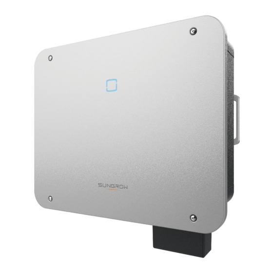
2 Product Description User Manual Product Introduction Model Description The model description is as follows (take SG30CX—P2 as an example): Appearance The following figure shows the appearance of the inverter. - Page 17 User Manual 2 Product Description figure 2-2 Appearance The image shown here is for reference only. The actual product received may differ. Description Name To indicate the current working state of the inverter. LED indicator Mounting ears To hang the inverter onto the mounting-bracket. Handles To move the inverter.
-
Page 18: Symbols On The Product
2 Product Description User Manual figure 2-3 Dimensions of the Inverter(in mm) Weight Model Weight SG25/30/33CX-P2 38 kg SG36/40CX-P2 40 kg SG50CX-P2 41 kg Symbols on the Product Symbol Explanation Do not dispose of the inverter together with household waste. Read the user manual before maintenance! TÜV mark of conformity. -
Page 19: Led Indicator
User Manual 2 Product Description Symbol Explanation Danger to life due to high voltages! Do not touch live parts for 15 minutes after disconnection from the power sources. Only qualified personnel can open and maintain the inverter. External grounding point. * The table shown here is for reference only. -
Page 20: Circuit Diagram
2 Product Description User Manual Voltage may still be present in AC side circuits after the indicator is off. Pay atten- tion to the electricity safety during operating. Circuit Diagram The following figure shows the main circuit of the inverter. figure 2-4 Circuit Diagram •... - Page 21 • The communication accessory port is used to connect communication module manufac- tured by SUNGROW, and upload monitoring data through communication cables or wire- less communication. The inverter can be connected to communication devices via either of the two interfaces.
- Page 22 2 Product Description User Manual • Before enabling the PID recovery function, make sure the voltage polarity of the PV modules to ground meets requirement. If there are any questions, contact the PV module manufacturer or read the corresponding user manual. •...
-
Page 23: Unpacking And Storage
• Check the inner contents for damage after unpacking. Contact SUNGROW or the transport company in case of any damage or incompleteness, and provide photos to facilitate services. Do not dispose of the original packing case. It is recommended to store the device in the original packing case when the product is decommissioned. - Page 24 3 Unpacking and Storage User Manual • Do not store the inverter in places susceptible to direct sunlight, rain, and strong electric field. • Do not place the inverter in places with items that may affect or damage the inverter. •...
-
Page 25: Mechanical Mounting
Mechanical Mounting Respect all local standards and requirements during mechanical installation. Safety during Mounting Make sure there is no electrical connection before installation. Before drilling, avoid the water and electricity wiring in the wall. Poor installation environment will affect system performance! •... -
Page 26: Environment Requirements
4 Mechanical Mounting User Manual 4.2.1 Environment Requirements • The installation environment must be free of inflammable or explosive materials. • The location should be not accessible to children. • The ambient temperature and relative humidity must meet the following requirements. •... -
Page 27: Angle Requirements
Install the inverter vertically or at the maximum allowable rear tilt angle. Do not install the in- verter horizontally, forward, excessively backward, sideways, or upside down. Please consult SUNGROW before tilting backwards the inverter and install it in floating power plants. -
Page 28: Clearance Requirements
4 Mechanical Mounting User Manual • Ensure that the waterproof connectors are at least 300mm higher than the ground surface. • Bind the cables at the positions 300~350mm away from the DC connector, AC water- proof terminal, and communication waterproof terminal. •... - Page 29 User Manual 4 Mechanical Mounting The distance from the bottom of the inverter to the ground is determined according to the bending radius of the selected AC cable and the installation environment, and the following requirements should be met: • The distance from the bottom of the inverter to the ground should be ≥...
-
Page 30: Installation Tools
4 Mechanical Mounting User Manual Installation Tools Installation tools include but are not limited to the following recommended ones. If necessary, use other auxiliary tools on site. Goggles Earplugs Dust mask Protective gloves Insulated shoes Utility knife Wrist strap Marker Level Hammer drill Rubber mallet... -
Page 31: Moving The Inverter
User Manual 4 Mechanical Mounting Wrench Socket wrench set Wire cutter Wire stripper (16 mm, 60 mm) (M8) Hydraulic plier Heat gun MC4–Evo2 terminal MC4–Evo2 terminal crimping pliers wrench 4–6mm Multimeter Vacuum cleaner ≥ 1100 Vdc Moving the Inverter Before installation, remove the inverter from the packing case and move it to the installation site. -
Page 32: Installing The Mounting-Bracket
4 Mechanical Mounting User Manual Improper handling may cause personal injury! • Arrange an appropriate number of personnel to carry the inverter according to its weight, and installation personnel should wear protective equipment such as anti-impact shoes and gloves. • Attention must be paid to the center of gravity of the inverter to avoid tilting dur- ing handling. -
Page 33: Wall-Mounted Installation
User Manual 4 Mechanical Mounting step 2 Secure the mounting-bracket to the steel u-channel with bolts. - - End 4.5.2 Wall-Mounted Installation Tool preparation Name Specification — Maker Level Hammer drill Bit: φ12 Wrench Inner diameter: 16mm Material preparation Name Quantity Specification Source... -
Page 34: Pole Installation
4 Mechanical Mounting User Manual step 3 Secure the mounting-bracket with expansion bolts. - - End 4.5.3 Pole Installation Tool preparation Name Specification — Marker Level Hammer drill* Bit: φ12 Wrench Inner diameter: 16mm *Check if tools of other specifications are needed according to the bolts of the matching clamps. -
Page 35: Installing The Inverter
User Manual 4 Mechanical Mounting step 2 Mark and drill holes in steel u-channels according to the dimensions shown in the figure be- low. Two steel u-channels should be spaced 180 mm - 260 mm apart. step 3 Secure the mounting-bracket to the steel u-channels with bolts. step 4 Secure the steel u-channels to the pole with bolts and clamps. - Page 36 4 Mechanical Mounting User Manual Name Quantity Specification Source Cross screw M5×16 Included in the delivery scope step 1 Take out the inverter from the packing case. step 2 Lift the inverter onto the mounting-bracket and make sure the mounting ears fit well into the grooves of the mounting-bracket.
-
Page 37: Electrical Connection
Electrical Connection Safety Instructions The PV string will generate lethal high voltage when exposed to sunlight. • Operators must wear proper personal protective equipment during electrical connections. • Must ensure that cables are voltage-free with a measuring instrument before touching DC cables. •... -
Page 38: Terminal Description
5 Electrical Connection User Manual • All vacant terminals must be covered with waterproof covers to prevent affect- ing the protection rating. • When the wiring is completed, seal the gap of cable inlet and outlet holes with fireproof / waterproof materials such as fireproof mud to prevent foreign matter or moisture from entering and affecting the long-term normal operation of the inverter. -
Page 39: Electrical Connection Overview
User Manual 5 Electrical Connection Item Terminal Mark Note 6 pairs of terminals(SG25/30/ PV1,PV2, PV3, PV4, PV5, 33CX-P2) PV terminals 8 pairs of terminals(SG36/40/ PV1,PV2, PV3, PV4, PV5, PV6, PV7, PV8 50CX-P2) AC wiring Used for AC output cable terminal connection. - Page 40 5 Electrical Connection User Manual (A)PV string (B)Inverter (C)Grid (D)Monitoring device (E)AC circuit breaker table 5-3 Cable Requirements Specification Cable Di- Type Cable ameter Cross-sectional Area(mm (mm) Multi-core PV cable with a maximum with- 4.7 ~ 6.4 4 ~ 6 DC cable stand voltage of 1100V...
- Page 41 User Manual 5 Electrical Connection Specification Cable Di- Type Cable ameter Cross-sectional Area(mm (mm) Shielded twisted 0.5~1 pair Communi- cation 5.3 ~ 7 CAT 5E outdoor cable shielded network cable *A copper to aluminum adapter terminal is required when an aluminum cable is used. For details, refer to "...
-
Page 42: Crimp Ot / Dt Terminal
5 Electrical Connection User Manual Crimp OT / DT terminal Crimp OT / DT terminal 1. Heat shrink tubing 2. OT DT terminal 3. Hydraulic pliers 4. Heat gun Aluminium Cable Requirements If an aluminium cable is selected, use a copper to aluminium adapter terminal to avoid direct contact between the copper bar and the aluminium cable. -
Page 43: External Grounding Connection
AC side grounding terminal are reliably grounded. The grounding connection can be made by other means if they are in accordance with the local standards and regulations, and SUNGROW shall not be held liable for the possible consequences. 5.5.1 External Grounding Requirements All non-current carrying metal parts and device enclosures in the PV power system should be grounded, for example, brackets of PV modules and inverter enclosure. -
Page 44: Connection Procedure
5 Electrical Connection User Manual When there is only one inverter in the PV system, connect the external grounding cable to a nearby grounding point. When there are multiple inverters in the PV system, connect grounding points of all inverters and the PV array frames to the equipotential cable (according to the onsite conditions) to im- plement an equipotential connection. - Page 45 AC Circuit Breaker An independent circuit breaker or fuse should be installed on the output side of the inverter to ensure safe disconnection from the grid. Recommended rated Recommended rated voltage Inverter current SG25CX-P2 400V 63 A SG30CX-P2 400V 63 A SG33CX-P2...
-
Page 46: Requirements For Ot/Dt Terminal
5 Electrical Connection User Manual 5.6.2 Requirements for OT/DT Terminal OT / DT terminals (not included in the delivery scope) are required for fixing AC cables to the terminal block. Purchase the OT / DT terminals according to the following requirements. OT / DT Terminals of Phase Wire •... - Page 47 User Manual 5 Electrical Connection step 4 Remove the AC protective cap. step 5 Secure the wires to corresponding terminals. Gently pull the cable backwards to ensure firm connection. Observe the terminal layout on the block. Do not connect the phase wires to "PE" terminal or "N"...
- Page 48 5 Electrical Connection User Manual Ensure that the depth L of the socket used is not less than 18mm. step 6 Secure the junction box.
- Page 49 User Manual 5 Electrical Connection Ensure that the junction box is properly assembled. Failure to do so may affect the waterproof performance of the AC side, and the loss caused by this is not covered by the warranty. step 7 Gently pull the cable backwards to ensure firm connection, and fasten the swivel nut clockwise.
-
Page 50: Dc Cable Connection
The damage caused by this is not covered by the warranty. • Electric arc or contactor over-temperature may occur if the PV connectors are not firmly in place, and SUNGROW shall not be held liable for any damage caused. •... -
Page 51: Pv Input Configuration
User Manual 5 Electrical Connection The following requirements about PV string connection must be met. Otherwise, it may cause irreversible damage to the inverter, which is not covered by the warranty. • Mixed use of different brand or model of PV modules in one MPPT circuit, or PV modules of different orientation or angles in a string may not damage inverter but will cause system bad performance! •... -
Page 52: Assembling The Pv Connectors
• Do not connect the AC circuit breaker before finishing electrical connection. SUNGROW provides corresponding PV connectors in the scope of delivery for quick connection of PV inputs. To ensure IP66 protection, use only the supplied connector or the connector with the same ingress of protection. -
Page 53: Installing The Pv Connector
User Manual 5 Electrical Connection step 5 Check for polarity correctness. If the PV polarity is reversed, the inverter will be in a fault or alarm state and will not operate normally. - - End 5.7.3 Installing the PV Connector step 1 Ensure that the DC switch is in "OFF"... -
Page 54: Communication Connection
5 Electrical Connection User Manual step 3 Connect the PV connectors to corresponding terminals until there is an audible click. step 4 Follow the foregoing steps to connect PV connectors of other PV strings. step 5 Seal any unused PV terminal with a terminal cap. - - End Communication Connection 5.8.1 Wireless Communication Module Connection (optional) -
Page 55: Winet-S Connection (Optional)
User Manual 5 Electrical Connection Once the communication module is in use, do not connect the inverter to a 3rd party data logger at the same time via RS485. For details on module installation and configuration, refer to the manual delivered together with the module. - Page 56 5 Electrical Connection User Manual step 3 Unscrew the housing from the communication module. step 4 Thread the network cable through the swivel nut and gasket. Afterwards, route the cable into the opening of the sealing. Finally, insert the cable through the housing. step 5 Insert the RJ45 plug into the front plug connector until there is an audible click and tighten the housing.
-
Page 57: Rs485 Connection
User Manual 5 Electrical Connection step 6 Remove the waterproof lid from the COM1 terminal and install WiNet-S. step 7 Slightly shake it by hand to determine whether it is installed firmly. - - End 5.8.2.2 WLAN Communication step 1 Remove the waterproof lid from the COM1 terminal. step 2 Install the module. - Page 58 5 Electrical Connection User Manual In case of multiple inverters, all the inverters can be connected via RS485 cables in the daisy chain manner, as shown in the following figure. 5.8.3.1 Assembling the COM Connector step 1 Unscrew the swivel nut from the connector. step 2 Take out the terminal block.
- Page 59 User Manual 5 Electrical Connection step 4 Remove the cable jacket and strip the wire insulation. step 5 Plug the wires into the RS485 terminal according the labels on the bottom of the inverter. step 6 Pull the wires outward to check whether they are firmly installed. step 7 Insert the terminal block into the connector until it snaps into place with an audible click.
-
Page 60: Smart Energy Meter Connection
For the setting of feed-in power limit, refer to the section "7.3.2 Login Procedure" Contact SUNGROW to ensure that the Smart Energy Meter model is available locally. This section mainly describes the cable connections on the inverter side. Refer to the quick guide delivered with the Smart Energy Meter for the connections on the meter side. -
Page 61: Dry Contact Connection
User Manual 5 Electrical Connection Procedure For detailed connection description of the Smart Energy Meter cable, refer to the section "5.8.3 RS485 Connection". Plug the wires into the Meter terminal according the labels on the bottom of the inverter. 5.8.5 Dry Contact Connection Dry contact cables require a cross section of 1 mm to 1.5 mm The connection procedure of the dry contact is the same as that of the RS485... -
Page 62: Drm Connection
Close S1 and S5 Enable the DRM function through the iSolarCloud APP. If there are any problems, contact your distributor first. If the problem persists, contact SUNGROW. The DRM function is only applicable to devices for Australia and New Zealand. - Page 63 User Manual 5 Electrical Connection table 5-6 Method of Asserting DI Mode Output power (in % of the Max. Switch Operation on AC output power) External RCR None 100% Close S1 100% Close S2 Close S3 0% (disconnect from grid) Close S1 and S2 5.8.6.1 Assembling the COM Connector step 1 Unscrew the swivel nut from the connector.
- Page 64 5 Electrical Connection User Manual step 4 Remove the cable jacket by 7 mm–10 mm. step 5 Plug the wires into the corresponding terminal according the labels on the bottom of the inverter. step 6 Pull the wires outward to check whether they are firmly installed. step 7 Insert the terminal block into the connector until it snaps into place with an audible click.
- Page 65 User Manual 5 Electrical Connection - - End 5.8.6.2 Installing the COM Connector step 1 Remove the waterproof lid from the COM terminal. step 2 Insert the COM connector into COM terminal on the bottom of the inverter until there is an audible click.
-
Page 66: Commissioning
Commissioning Inspection before Commissioning Check the following items before starting the inverter: • All equipment has been reliably installed. • DC switch(es) and AC circuit breaker are in the "OFF" position. • The ground cable is properly and reliably connected. •... - Page 67 User Manual 6 Commissioning step 5 The home page is automatically displayed when the initialization is completed. The indicator is steady blue, and the inverter is in grid-connected operation. - - End...
-
Page 68: Isolarcloud App
iSolarCloud App Brief Introduction The iSolarCloud App can establish communication connection to the inverter via the Blue- tooth, thereby achieving near-end maintenance on the inverter. Users can use the App to view basic information, alarms, and events, set parameters, or download logs, etc. Screenshots in this manual are based on the Android system V2.1.6 , and the ac- tual interfaces may differ. -
Page 69: Login
User Manual 7 iSolarCloud App Login 7.3.1 Requirements The following requirements should be met: • The AC or DC side of the inverter is powered-on. • The mobile phone is within 5 meters away from the inverter and there are no obstructions in between. - Page 70 7 iSolarCloud App User Manual figure 7-1 Bluetooth Connection step 3 Enter the identity verification screen after the Bluetooth connection is established.
- Page 71 If the dis- tributor is unable to provide the required information, contact SUNGROW. step 4 If the inverter is not initialized, you will enter the quick setting screen of initializing protection parameter.
- Page 72 7 iSolarCloud App User Manual figure 7-4 Initialization Power Company The image shown here is for reference only. Refer to the actual interface for the supported network service providers. table 7-1 Power Company Information Grid Type Network Service Provider AS/NZS 4777.2:2015 AS/NZS 4777.2:2020 Australia A AS/NZS 4777.2:2020 Australia B AS/NZS 4777.2:2020 Australia C...
- Page 73 User Manual 7 iSolarCloud App Grid Type Network Service Provider SA Power Networks • TS129-2019: < 10 kW for single-phase & 30 kW for three-phase • TS130-2017: > 30 kW & ≤ 200 kW • TS131-2018: > 200 kW Horizon Power •...
-
Page 74: Function Overview
7 iSolarCloud App User Manual Function Overview The App provides parameter viewing and setting functions, as shown in the following figure. figure 7-5 App function tree map Home page After login, the home page is as follows:... - Page 75 User Manual 7 iSolarCloud App figure 7-6 Home Page table 7-3 Home Page Description Designation Description System date and time of the inverter. Date and time Present operation state of the inverter. For details, refer to Inverter state "table 7-4 Description of Inverter State".
-
Page 76: Run Information
7 iSolarCloud App User Manual table 7-4 Description of Inverter State Description State After being energized, the inverter tracks the PV arrays’ maximum power point (MPP) and converts the DC power into AC power. This is the nor- mal operation mode. Stop The inverter is stopped. - Page 77 User Manual 7 iSolarCloud App table 7-6 Run Information Classifica- Description Parameter tion String n Voltage The input voltage of the n string String n current The input current of the n string Information Total On-grid Run- ning Time Daily On-grid Run- ning Time Negative Voltage to Inverter DC side negative to ground voltage value...
-
Page 78: Records
7 iSolarCloud App User Manual Classifica- Description Parameter tion Phase C Current Records Tap Records on the navigation bar to enter the screen showing event records, as shown in the following figure. figure 7-7 Records Fault Alarm Record Tap Fault Alarm Record to enter the screen, as shown in the following figure. figure 7-8 Fault Alarm Record Click to select a time segment and view corresponding records. - Page 79 User Manual 7 iSolarCloud App figure 7-9 Detailed Fault Alarm Information Yield Record Tap Yield Record to enter the screen showing daily power generation , as shown in the fol- lowing figure. figure 7-10 Power Curve The App displays power generation records in a variety of forms, including daily power gen- eration graph, monthly power generation histogram, annual power generation histogram and total power generation histogram.
-
Page 80: More
7 iSolarCloud App User Manual Description Parameter Monthly energy Shows the power output every month in a year. histogram Annual energy Shows the power output every year. histogram Tap the time bar on the top of the screen to select a time segment and view the correspond- ing power curve. -
Page 81: Operation Parameters
User Manual 7 iSolarCloud App figure 7-12 System Parameters * The image shown here is for reference only. Boot/Shutdown Tap Boot/Shutdown to send the boot/shutdown instruction to the inverter. Date Setting/Time Setting The correct system time is very important. Wrong system time will directly affect the data logging and power generation value. - Page 82 7 iSolarCloud App User Manual figure 7-14 PID Setting table 7-8 PID Parameter Description Description Parameter Set enabling/disabling of the PID night recovery function. PID night PID Recovery recovery function operates between 22:00 pm and 5:00 am by default. If ISO impedance abnormality or PID function exception is de- tected during running of the PID function, the inverter reports a Clear PID alarm PID false alarm and reminds the user to take corresponding meas-...
-
Page 83: Power Regulation Parameters
User Manual 7 iSolarCloud App figure 7-16 Regular Parameters Setting 7.8.3 Power Regulation Parameters Active Power Regulation Tap Settings→Power Regulation Parameters→Active Power Regulation to enter the screen, as shown in the following figure. figure 7-17 Active Power Regulation table 7-9 Active Power Regulation Definition/Setting Range Parameter... - Page 84 7 iSolarCloud App User Manual Definition/Setting Range Parameter Description Active power gradient Switch for enabling/disabling Enable/Disable control the active power rate settable function. Active power decline The decline rate of inverter ac- 1%/min~6000%/min gradient tive power per minute. Active power rising The rise rate of inverter active 1%/min~6000%/min gradient...
- Page 85 User Manual 7 iSolarCloud App figure 7-18 Reactive Power Regulation table 7-10 Reactive Power Regulation Definition/Setting Range Parameter Description Reactive power gener- Switch for enabling/disabling Enable/Disable ation at night reactive power generation at night function. Reactive power ratio Reactive power ratio set for -100%~0%/ at night the reactive power generation...
- Page 86 7 iSolarCloud App User Manual table 7-11 Descriptions of reactive power regulation mode: Descriptions Mode The PF is fixed at +1.000. The reactive power can be regulated by the parameter PF (Power Factor). The reactive power can be regulated by the parameter Q-Var limits (in %). Q(P) The PF changes with the output power of the inverter.
- Page 87 User Manual 7 iSolarCloud App Explanation Range Parameter Voltage percentage for Q(P) function 100% ~ 110% EnterVoltage activation Voltage percentage for Q(P) function QP_ExitVoltage 90% ~ 100% deactivation Power percentage for Q(P) function QP_ExitPower 1% ~ 100% deactivation Unconditional activation/deactivation of Q QP_EnableMode Yes / No (P) function...
-
Page 88: Communication Parameters
7 iSolarCloud App User Manual Explanation Range Parameter Grid voltage limit at P4 on the Q(U) mode QU_V4 100% ~ 120% curve Value of Q/Sn at P4 on the Q(U) mode QU_Q4 0 ~ 60% curve QU_EnterPower Active power for Q(U) function activation 20% ~ 100% QU_ExitPower Active power for Q(U) function deactivation... -
Page 89: Password Changing
User Manual 7 iSolarCloud App step 3 Tap More→Firmware Download to enter corresponding screen on which you can view the device list. step 4 Select the device model before downloading the firmware. Tap the device name in the de- vice list to enter the firmware upgrade package detail interface, and tap behind the firm- ware upgrade package to download it. - Page 90 7 iSolarCloud App User Manual figure 7-22 Change Password The password shall consisit of 8–20 digits, including letters and numbers.
-
Page 91: System Decommissioning
System Decommissioning Disconnecting the Inverter Danger of burns! Even if the inverter is shut down, it may still be hot and cause burns. Wear protec- tive gloves before operating the inverter after it cools down. For maintenance or other service work, the inverter must be switched off. Proceed as follows to disconnect the inverter from the AC and DC power sources. -
Page 92: Disposal Of The Inverter
8 System Decommissioning User Manual step 2 Refer to"4 Mechanical Mounting", to dismantle the inverter in reverse steps. step 3 If necessary, remove the wall-mounting bracket from the wall. step 4 If the inverter will be used again in the future, please refer to "3.2 Inverter Storage"... -
Page 93: Troubleshooting And Maintenance
App or the LCD. Modify the overvoltage protection values with the con- sent of the local electric power operator. 3. Contact Sungrow Customer Service if the pre- ceding causes are ruled out and the fault persists. Generally, the inverter will be reconnected to the grid after the grid returns to normal. - Page 94 2. Check whether the protection parameters are appropriately set via the App or the LCD. 3. Contact Sungrow Customer Service if the pre- ceding causes are ruled out and the fault persists. Generally, the inverter will be reconnected to the grid after the grid returns to normal.
- Page 95 App or the LCD. 3. Contact Sungrow Customer Service if the pre- ceding causes are ruled out and the fault persists. 1. Check whether the corresponding string is of reverse polarity.
- Page 96 3. Check if the DC fuse is damaged. If so, replace Alarm the fuse. 4. Contact Sungrow Customer Service if the pre- ceding causes are ruled out and the alarm persists. *The code 548 to code 563 are corresponding to string 1 to string 16 respectively.
- Page 97 If so, replace the dam- aged cable and secure terminals to ensure a reli- able connection. 5. Contact Sungrow Customer Service if the pre- ceding causes are ruled out and the fault persists. 1. Check whether the AC cable is correctly connected.
- Page 98 2. Reconnect the communication cable of the cation Abnormal meter. Alarm 3. Contact Sungrow Customer Service if the pre- ceding causes are ruled out and the alarm persists. 1. Check whether the output port is connected to actual grid. Disconnect it from the grid if so.
- Page 99 Close the AC and DC switches in turn 15 248–255, 300– minutes later and restart the system. 322, 324–328, 3. Contact Sungrow Customer Service if the pre- 401–412, 600– ceding causes are ruled out and the fault persists. 603, 605, 608, 612, 616, 620, 622–624, 800,...
- Page 100 Close the AC and DC switches in turn 15 364-395 minutes later and restart the system. Overvoltage Fault 2. If the fault persists, please contact Sungrow Power Customer Service. 1. Check whether the number of PV modules of the corresponding string is less than other strings.
-
Page 101: Maintenance
3. Do not reinsert the faulty strings before the grounding fault is cleared; 4. If the fault is not caused by the foregoing rea- sons and still exists, contact Sungrow Customer Service. 1. It is prohibited to disconnect the DC switch when the DC current is greater than 0.5 A when... -
Page 102: Routine Maintenance
To avoid the risk of electric shock, do not perform any other maintenance opera- tions beyond this manual. If necessary, contact SUNGROW for maintenance. Oth- erwise, the losses caused is not covered by the warranty. -
Page 103: Cleaning Air Inlet And Outlet
User Manual 9 Troubleshooting and Maintenance Item Method Period Check whether the cable entry is in- sufficiently sealed or the gap is exces- Cable entry Once a year sively large, and reseal the entry when necessary. Check whether all cable are firmly connected in place. - Page 104 9 Troubleshooting and Maintenance User Manual step 4 Pull out the fan module, clean the fans with soft brush or vacuum cleaner, and replace them when necessary. step 5 Reinstall the fan back to the inverter in reverse order and restart the inverter. - - End...
-
Page 105: Appendix
10 Appendix 10.1 Technical Data SG30CX-P2 SG33CX-P2 Parameters SG25CX-P2 Input (DC) Recommended max. 35 kWp 42 kWp 46.2 kWp PV input power Max. PV input voltage 1100 V Min. PV input voltage / 160 V / 200 V Startup input voltage... - Page 106 10 Appendix User Manual SG30CX-P2 SG33CX-P2 Parameters SG25CX-P2 Rated grid frequency 50 Hz / 60 Hz Grid frequency range 45 – 55 Hz / 55 – 65 Hz < 3 % (at Rated power) Harmonic (THD) Power factor at Rated >...
- Page 107 User Manual 10 Appendix SG30CX-P2 SG33CX-P2 Parameters SG25CX-P2 Topology Transformerless Degree of protection IP66 Corrosion Night power < 5W consumption Operating ambient -30 to 60 ℃ temperature range Allowable relative hu- 0 – 100 % midity range (non- condensing) Cooling method Smart forced air cooling Max.
- Page 108 10 Appendix User Manual SG40CX-P2 SG50CX-P2 Parameters SG36CX-P2 No. of PV strings per MPPT 120 A (30 A * 4) Max. PV input current 160 A (40 A * 4) Max. DC short-circuit current Max. current for DC connector Output (AC) Rated AC output 36 kVA 40 kVA...
- Page 109 User Manual 10 Appendix SG40CX-P2 SG50CX-P2 Parameters SG36CX-P2 AC short-circuit protection Leakage current protection Surge protection DC Type I+II / AC Type II Ground fault monitoring DC switch PV String current monitoring Arc fault circuit inter- rupter (AFCI) PID recovery function General Data Dimensions (W*H*D) 645*575*245 mm...
- Page 110 10 Appendix User Manual SG40CX-P2 SG50CX-P2 Parameters SG36CX-P2 AC connection type OT terminal OT terminal (16~35 OT or DT terminal (16~35 mm²) mm²) (35~50 mm²) AC Cable specification Outside diameter 18~38mm Grid Support Q at night function, LVRT, HVRT,active & reactive power control and power ramp rate control SG50CX-P2 (2)...
- Page 111 User Manual 10 Appendix SG50CX-P2 (2) Parameters SG30CX-P2 (2) 312 - 480 V AC voltage range 50 Hz / 60 Hz Rated grid frequency 45 – 55 Hz / 55 – 65 Hz Rated grid frequency+B42:H42 < 3 % (at rated power) Harmonic (THD) >...
-
Page 112: Wring Distance Of Di Dry Contact
10 Appendix User Manual SG50CX-P2 (2) Parameters SG30CX-P2 (2) Corrosion < 4W Night power consumption -30 to 60 ℃ (> 45 ℃ derating) Operating ambient temperature range 0 – 100 % Allowable relative humidity range (non-condensing) Smart forced air cooling Cooling method 4000 m Max. - Page 113 User Manual 10 Appendix Maximum wiring distance(unit:m) Number of inverter 16AWG / 1.31mm 17AWG / 1.026mm 3258 2638 2606 2110 2172 1759 1861 1507 1629 1319 1448 1172 1303 1055 1185 1086 1002 In case the specification of the cable used is not included in the Table above, when there is only one inverter, ensure that the line impedance of the input node is less than 300Ω;...
-
Page 114: Quality Assurance
• The customer shall give SUNGROW a reasonable period to repair the faulty device. Exclusion of Liability In the following circumstances, SUNGROW has the right to refuse to honor the quality guarantee: • The free warranty period for the whole machine/components has expired. - Page 115 Sungrow Power Supply Co., Ltd. www.sungrowpower.com...
Need help?
Do you have a question about the SG25CX-P2 and is the answer not in the manual?
Questions and answers