
Related Manuals for Sungrow SG25CX-SA


Summary of Contents for Sungrow SG25CX-SA
- Page 1 User Manual PV Grid-Connected Inverter SG25CX-SA SG25CX-SAPV Grid-Connected InverterUser ManualSG25CX-SA-UEN-Ver13- 202304 SG25CX-SA-UEN-Ver13-202304...
-
Page 3: All Rights Reserved
Software Licenses • It is prohibited to use data contained in firmware or software developed by SUNGROW, in part or in full, for commercial purposes by any means. • It is prohibited to perform reverse engineering, cracking, or any other operations that compromise the original program design of the software developed by SUNGROW. -
Page 4: About This Manual
Validity This manual is valid for the following inverter types: • SG25CX-SA They will be referred to as “inverter” hereinafter unless otherwise specified. Target Group This manual is intended for: •... -
Page 5: Table Of Contents
Contents All Rights Reserved .....................I About This Manual......................II 1 Safety .........................1 1.1 PV Panels......................1 1.2 Utility Grid ......................1 1.3 Inverter ......................2 1.4 Skills of Qualified Personnel ................3 2 Product Introduction ..................4 2.1 Intended Usage....................4 2.2 Product Introduction..................5 2.2.1 Model Description .................5 2.2.2 Appearance ..................6 2.2.3 Dimensions ..................6 2.2.4 LED Indicator Panel ................7... - Page 6 4.4.1 Manual Transport ................20 4.4.2 Hoisting Transport................20 4.5 Dimensions of mounting-bracket..............21 4.6 PV Bracket-Mounted Installation ..............22 4.6.1 Preparation before Mounting..............22 4.6.2 Mounting Steps...................22 4.7 Wall-Mounted Installation ................24 4.7.1 Preparation before Mounting..............24 4.7.2 Mounting Steps...................25 5 Electrical Connection ..................28 5.1 Safety Instructions ..................28 5.2 Terminal Description ..................28 5.3 Electrical Connection Overview ..............30 5.4 Additional Grounding Connection..............31...
- Page 7 5.11 Wi-Fi Communication Module Connection ............51 6 Commissioning ....................53 6.1 Inspection before Commissioning ..............53 6.2 Commissioning Procedure ................53 7 iSolarCloud App ....................54 7.1 Brief Introduction ..................54 7.2 Download and Install..................54 7.3 Login ......................55 7.3.1 Requirements ..................55 7.3.2 Login Steps ..................55 7.4 Function Overview..................58 7.5 Home page ....................58 7.6 Running Information ..................61...
-
Page 9: Safety
The safety instructions in this manual cannot cover all the precautions that should be followed. Perform operations considering actual onsite conditions. SUNGROW shall not be held liable for any damage caused by violation of the safety instructions in this manual. -
Page 10: Inverter
1 Safety User Manual Inverter Danger to life from electric shocks due to live voltage • Do not open the enclosure at any time. Unauthorized opening will void guarantee and warranty claims and in most cases terminate the operating license. Risk of inverter damage or personal injury •... -
Page 11: Skills Of Qualified Personnel
User Manual 1 Safety Warning Label Description Label Danger to life due to high voltages! Only qualified personnel can open and service the inverter. Disconnect the inverter from all the external power sources before service! Do not touch live parts until 5 minutes after disconnection from the power sources. -
Page 12: Product Introduction
Product Introduction Intended Usage SG25CX-SA, a transformerless three-phase PV grid-connected inverter, is an integral component in the PV power system. The inverter is designed to convert the direct current power generated from the PV modules into grid-compatible AC current and feeds the AC current to the utility grid. The intended usage of the inverter is illustrated in "figure 2-1 Inverter application in PV power... -
Page 13: Product Introduction
The device model description is as follows: Nominal Output Power Nominal Grid Voltage Model SG25CX-SA 25000W 3/N/PE AC 220/127 V The device model can be found on the nameplate attached to the side of the inverter. For details, refer to "3.2 Identifying the... -
Page 14: Appearance
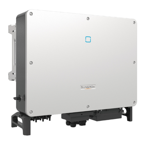
2 Product Introduction User Manual 2.2.2 Appearance *The image shown here is for reference only. The actual product you receive may differ. Description Name LED indicator panel HMI interface to indicate the present working state of the inverter. Mounting ears 4, used to hang the inverter onto the mounting-bracket. -
Page 15: Led Indicator Panel
User Manual 2 Product Introduction Type Dimensions (W*H*D) Weight SG25CX-SA 54 kg 782×645×310mm 2.2.4 LED Indicator Panel As an HMI, the LED indicator panel on the front of the inverter can indicate the present working state of the inverter. table 2-1 LED indicator description... -
Page 16: Function Description
2 Product Introduction User Manual feeds the AC power into the utility grid through the AC terminal. The protection circuit is equipped to ensure the safe operation of the device and personal safety. The following figure shows the main circuit of the inverter. figure 2-3 Circuit diagram Function Description The inverter is equipped with the following functions:... - Page 17 User Manual 2 Product Introduction Protection Function The protective functions are integrated in the inverter, including anti-island protection, LVRT/ ZVRT, DC reversed polarity protection, AC short circuit protection, leakage current protection, DC overvoltage/overcurrent protection, etc. PID function After the PID function is enabled, the voltage to ground of all PV modules is greater than 0, that is, the PV module-to-ground voltage is a positive value.
-
Page 18: Unpacking And Storage
Check the delivery scope for completeness according to the packing list. Contact SUNGROW or the supplier in case there is any damage or incompleteness. Do not dispose of the original packing case. It is recommended to store the inverter in it. - Page 19 3-1 Nameplate of Inverters * The image shown here is for reference only. The actual product you receive may differ. Description Item SUNGROW logo and product type Technical data of inverter Instructions and marks of conformity Company name, website and country of manufacture...
-
Page 20: Scope Of Delivery
3 Unpacking and Storage User Manual Scope of Delivery figure 3-2 Scope of Delivery a. The mounting-bracket includes 2 mounting-bracket components and 1 connecting bar. b. The screws include 1 M4×25 screw, 3 M4×10 screws, and 2 M6×65 screws. c. The documents include the quick installation guide, packing list, warranty card, etc. Inverter Storage Proper storage is required if the inverter is not installed immediately. - Page 21 User Manual 3 Unpacking and Storage • The packing case should be upright. • If the inverter has been stored more than half a year, the qualified personnel should thoroughly check and test it before using.
-
Page 22: Mechanical Mounting
Mechanical Mounting Safety during Mounting Make sure there is no electrical connection before installation. In order to avoid electric shock or other injury, be sure there is no electricity or plumbing installations before drilling holes. Risk of injury due to improper handling •... -
Page 23: Carrier Requirements
The installation carrier should meet the following requirements: 4.2.3 Installation Angle Requirements Inverter vertically or at a minimum back tilt of 10°. Forward installation or upside down installation is prohibited. Please consult SUNGROW before tilting backwards the inverter and install it in floating power plants. -
Page 24: Installation Clearance Requirements
4 Mechanical Mounting User Manual In case the installation site is a level surface, mount the inverter to the horizontal- mounting bracket to meet the mounting angle requirements, as shown in the figure below. Take the following items into account when designing the bracket scheme: •... - Page 25 User Manual 4 Mechanical Mounting * The distance can be shortened to 200mm according to onsite conditions. In case the distance is less than 600mm, move the inverter from the mounting-bracket or wall before maintaining fans. The distance between the bottom of the inverter and the ground surface is determined according to the bending radius of the AC cable used and the installation environment.
- Page 26 4 Mechanical Mounting User Manual • Install the inverter at an appropriate height for ease of viewing LED indicators and operating switches.
-
Page 27: Installation Tools
User Manual 4 Mechanical Mounting Installation Tools Installation tools include but are not limited to the following recommended ones. If necessary, use other auxiliary tools on site. table 4-1 Tool specification Specification M2/M6 M4/M6/M8 Drill bit: φ12, φ14 Includes sleeve with opening size 16mm Opening:13mm, 16mm Crimp range 4~6mm Range≥1100Vdc... -
Page 28: Moving The Inverter
4 Mechanical Mounting User Manual Moving the Inverter Move the inverter to the specified position before installation. The inverter can be moved manually or via a hoist. 4.4.1 Manual Transport Lift and move the inverter to the destination by using the side handles and bottom handles. Inappropriate moving operation may cause personal injury!... -
Page 29: Dimensions Of Mounting-Bracket
User Manual 4 Mechanical Mounting step 2 Lead the sling through the two lifting rings and fasten the tie-down strap. step 3 Hoist the inverter, and stop to check for safety when the inverter is 100mm above the ground. Continue hoisting the device to the destination after ensuring the safety. step 4 Remove the lifting rings and reassemble the sealing screws released in Step 1. -
Page 30: Pv Bracket-Mounted Installation
4 Mechanical Mounting User Manual figure 4-1 Dimensions of mounting-bracket PV Bracket-Mounted Installation 4.6.1 Preparation before Mounting Tools Specification Item Phillips screwdriver/ electric M4, M6 screw driver Marker Level Drill bit: φ12 Hammer drill Including 16mm socket Socket wrench Opening: 16mm wrench Spare parts Quantity... - Page 31 User Manual 4 Mechanical Mounting step 2 Level the assembled mounting-bracket by using the level, and mark the positions for drilling holes on the PV bracket. Drill the holes by using a hammer drill. step 3 Secure the mounting-bracket with bolts. table 4-2 Fastening sequence Components Description...
-
Page 32: Wall-Mounted Installation
4 Mechanical Mounting User Manual step 6 Hang the inverter to the mounting-bracket and ensure that the mounting ears perfectly engage with the mounting-bracket. step 7 Fix the inverter with two M6×65 screws. - - End Wall-Mounted Installation 4.7.1 Preparation before Mounting Tools Specification Item... -
Page 33: Mounting Steps
User Manual 4 Mechanical Mounting Spare parts Quantity Specification Item Source Delivery scope M4×10 Grub screw Delivery scope M6×65 M10×95 Expansion bolts Self-prepared (Recommended) 4.7.2 Mounting Steps step 1 Assemble the mounting-bracket by using the connecting bar. step 2 Level the assembled mounting-bracket by using the level, and mark the positions for drilling holes on the installation site. - Page 34 4 Mechanical Mounting User Manual table 4-3 Fastening sequence Designation Description Item Wall Fastening the bolt in the sequence of nut, spring washer, slat Expansion bolt washer Mounting- bracket step 5 Take out the inverter from the packing case. step 6 Hoist the inverter to the installation position when necessary (refer to "4.4.2 Hoisting Transport").
- Page 35 User Manual 4 Mechanical Mounting - - End...
-
Page 36: Electrical Connection
Electrical Connection Safety Instructions Prior to any electrical connections, keep in mind that the inverter has dual power supplies. It is mandatory for the qualified personnel to wear personal protective equipments (PPE) during the electrical work. Danger to life due to a high voltage inside the inverter! •... - Page 37 User Manual 5 Electrical Connection figure 5-1 Wiring terminals * Figure shown here is for reference only. The actual product you receive may differ! Item Terminal Mark Note PV terminals + / - MC4 PV connector For RS485 communication wiring. COM1 COM2 For Communication module connection.
-
Page 38: Electrical Connection Overview
5 Electrical Connection User Manual Electrical Connection Overview Electrical connection in the PV system includes additional grounding connection, AC connection, and PV string connection. Designation Item PV string Inverter Grid Monitoring device ACcircuit breaker communication module table 5-1 Cable requirements Specification Cable Type... -
Page 39: Additional Grounding Connection
User Manual 5 Electrical Connection Specification Cable Type Cross-sectional area Cable Diameter (mm) CAT-5 Ethernet cable (RJ45) table 5-2 PE wire requirements Phase wire cross PE wire cross Note section S section 16<S≤35mm 16 mm The specifications are valid only when the phase wire and PE wire use the same material. -
Page 40: Ac Cable Connection
5 Electrical Connection User Manual 1:Heat shrink tubing 2:OT/DT terminal step 2 Remove the screw on the grounding terminal and fasten the cable with a screwdriver. step 3 Apply paint to the grounding terminal to ensure corrosion resistance. - - End The grounding screws have been anchored to the side of the inverter before delivery, and do not need to be prepared. - Page 41 Multiple inverters can not share one circuit breaker Multiple Inverters in parallel Connection If multiple inverters are connected in parallel to the grid, ensure that the total number of parallel inverters does not exceed 30. Otherwise, please contact SUNGROW for technical scheme. MV transformer The MV transformer used together with the inverter should meet the following requirements: •...
-
Page 42: Requirements For Ot/Dt Terminal
The apparent power of the inverter should never exceed the power of the transformer. The maximum AC current of all inverters connected in parallel must be taken into account. If more than 30 inverters are connected to the grid, contact SUNGROW. •... -
Page 43: Connection Procedure
User Manual 5 Electrical Connection figure 5-3 Aluminium cable terminal connection sequence Ensure that the selected terminal can directly contact with the copper bar. If there are any problems, contact the manufacturer of terminal. Direct contact between the copper bar and the aluminium cable will cause electrochemical corrosion and impair the reliability of electrical connection. - Page 44 5 Electrical Connection User Manual step 4 Make the cable and crimp OT terminal. step 5 Unfasten the buckle and remove the protective cap. step 6 Secure the cable to corresponding terminals. Observe the terminal layout on the block. Do not connect the phase wires to "PE" terminal or PE wire to "N"...
- Page 45 User Manual 5 Electrical Connection Ensure that the depth L of the socket used is not less than 18mm. step 7 Secure the junction box, fasten the buckle, and secure it with supplied M4×10 screw. step 8 Gently pull the cable backwards to ensure firm connection, and fasten the swivel nut clockwise.
-
Page 46: Dc Cable Connection
5 Electrical Connection User Manual - - End DC Cable Connection Electric shock! The PV array will generate lethal high voltage once exposed to sunlight. Make sure the PV array is well insulated to ground before connecting it to the inverter. -
Page 47: Connection Procedure
SG25CX-SA 1100V 5.6.2 Connection Procedure SUNGROW provides corresponding plug connectors in the scope of delivery for quick connection of PV inputs. DC cables should be connected to the inverter via PV connectors which are included in the scope of delivery. -
Page 48: Installing The Pv Connectors
Use MC4– Evo2 DC terminals if the maximum input voltage is greater than 1,000V. To purchase the MC4–Evo2 DC terminals, contact SUNGROW. • Select appropriate DC terminals as required above. Otherwise, SUNGROW shall be held no liability for the damage caused. step 1 Strip the insulation from each DC cable by 7mm. - Page 49 Arc or contactor over temperature may occur if the PV connectors are not firmly in place, and SUNGROW shall not be held liable for any damage caused. step 4 Follow the foregoing steps to connect PV connectors of other PV strings.
-
Page 50: Communication Junction Box
5 Electrical Connection User Manual Communication Junction Box 5.7.1 Remove the Junction Box step 1 Pull out the pin and keep it properly, remove the junction box. The pin removed is a required accessory for fixing the junction box. Store it properly and protect it against missing or deformation. -
Page 51: Communication Wiring Board
User Manual 5 Electrical Connection Communication Wiring Board The communication board of the inverter includes two layers. The upper layer communication board mainly includes RS485 communication interfaces while The lower layer communication board mainly includes DI/DO interface and DRM interface. RS485 Communication 5.9.1 Interface Description As shown in the figure below, the inverter is equipped with three RS485 communication... -
Page 52: Rs485 Communication System
5 Electrical Connection User Manual The RS485-1 terminal block and the RJ45 interface can be applied to applications where multiple inverters communicate in a daisy-chain form. A 120Ω resistor can be connected in parallel between RS485-1 A/B pins by configuring the dip switch. - Page 53 User Manual 5 Electrical Connection When more than 15 inverters are connected on the same daisy chain, the inverters on two ends of the chain should be equipped with terminal resistors of 120Ω to ensure communication quality by configuring the dip switch (SW1), and the shielding layer of the communication cable should be single-point grounded.
-
Page 54: Connection Procedure(Terminal Block)
5 Electrical Connection User Manual 5.9.3 Connection Procedure(Terminal Block) RS485 communication cables should be shielded twisted pair cables or shielded twisted pair Ethernet cables. There are three communication terminals, and the silkscreen marks are COM1/ COM3/COM4. Please choose according to the actual situation. step 1 Remove the communication junction box, see "5.7.1 Remove the Junction Box". -
Page 55: Connection Procedure (Rj45 Network Port)
User Manual 5 Electrical Connection step 5 Insert the terminal base into the corresponding terminal. table 5-3 Terminal definition Definition RS485 A IN, RS485A differential signal+ RS485 A OUT, RS485A communication signal+ RS485 B IN, RS485B differential signal- RS485 B OUT, RS485B communication signal- step 6 If other wiring operations need to be performed on the communication board, finish the wiring operations before performing the following steps. - Page 56 5 Electrical Connection User Manual Outer diameter D(mm) Seal 4.5~6 6~12 13~18 step 3 Strip the insulation layer of the Ethernet cable with a wire stripper, and insert the signal wires to the RJ45 connector. Crimp the RJ45 connector with a crimping tool. step 4 Insert the RJ45 connector to the RJ45 jack.
-
Page 57: Dry Contact Connection
User Manual 5 Electrical Connection 5.10 Dry Contact Connection Dry contact cables require a cross section of 1 mm to 1.5 mm The connection procedure of the dry contact is the same as that of the RS485 terminal block. 5.10.1 Dry Contact Function The configuration circuit board is provided with fault output dry contact and emergency stop dry contact, as shown in the figure below. - Page 58 5 Electrical Connection User Manual figure 5-5 Normal open contact figure 5-6 Normal close contact Devices connected to the relay should comply with related requirements: AC-Side Requirements DC-Side Requirements Max. voltage: 250Vac Max. voltage: 30Vdc Max. current: 5A Max. current: 5A DI terminal (emergency stop dry contact): the dry contact can be configured to be an emergency stop contact.
-
Page 59: Wiring Procedure
User Manual 5 Electrical Connection figure 5-7 Local stop contact figure 5-8 Daisy chain topology When wiring DI dry contacts, ensure that the maximum wiring distance meet the requirements in "10.2 Wring Distance of DI Dry Contact". 5.10.2 Wiring Procedure Refer to the wiring of terminal block described in chapter 5.9.3 Connection Procedure 5.11 Wi-Fi Communication Module Connection Connect the Wi-Fi communication module within the delivery scope to the communication... - Page 60 5 Electrical Connection User Manual For details on module installation and configuration, refer to the manual delivered together with the module.
-
Page 61: Commissioning
Commissioning Inspection before Commissioning Check the following items before starting the inverter: • The inverter DC switch and external circuit breaker are disconnected. • The inverter should be accessible for operation, maintenance and service. • Nothing is left on the top of the inverter. •... -
Page 62: Isolarcloud App
iSolarCloud App Brief Introduction The iSolarCloud App can establish communication connection to the inverter via the Bluetooth, thereby achieving near-end maintenance on the inverter. Users can use the App to view basic information, alarms, and events, set parameters, or download logs, etc. *In case the communication module WiFi is available, the iSolarCloud App can also establish communication connection to the inverter via the mobile data or WiFi, thereby achieving remote maintenance on the inverter. -
Page 63: Login
User Manual 7 iSolarCloud App Login 7.3.1 Requirements The following items should meet requirements: • The AC or DC side of the inverter is powered-on. • The mobile phone is within 5m away from the inverter and there are no obstructions in between. - Page 64 7 iSolarCloud App User Manual figure 7-1 Bluetooth connection step 3 Enter the identity verification screen after the Bluetooth connection is established.
- Page 65 To set inverter parameters related to grid protection and grid support, contact SUNGROW to obtain the advanced account and corresponding password. step 4 If the inverter is not initialized, you will enter the quick setting screen of initializing protection parameter.
-
Page 66: Function Overview
7 iSolarCloud App User Manual In the European region, such as Netherlands, Sweden, Denmark, whose grid code complies with EN50549, select the parameter EN50549_1 (LV grid- connection) or EN50549_2 (MV grid-connection). In the Brazilian region, set the country code to "Brazil". Selecting "Brazil_230" or "Brazil_240"... - Page 67 User Manual 7 iSolarCloud App figure 7-5 Home page table 7-1 Home page description Designation Description System date and time of the inverter Date and time Present operation state of the inverter For details, refer to Inverter state Tab. 7-2Description of inverter state. Present state of the PID function For details, refer to Tab.
- Page 68 7 iSolarCloud App User Manual Designation Description Curve showing change of power between 5 am and 23 pm every day Power curve (Each point on the curve represents the percentage of present inverter power to rated power) Navigation bar Including "Home", "Run-info", "His-record", and "More" table 7-2 Description of inverter state Description State...
-
Page 69: Running Information
User Manual 7 iSolarCloud App Running Information Tap " " on the navigation bar to enter the running information screen, as shown in the following figure. figure 7-6 Running Information The run information includes the PV information, inverter information, input and output information. -
Page 70: History Record
7 iSolarCloud App User Manual Classificat- Description Parameter Voltage between the positive and negative poles Bus Voltage of the DC side of the inverter Internal Air Temperature Insulation resistance value of the input side to the Array Insulation protection ground Resistance Country Information Power Limitation... -
Page 71: Fault Alarm Records
User Manual 7 iSolarCloud App figure 7-7 History record On "history record" screen, users can check the alarm records, power yield records and event records. 7.7.1 Fault Alarm Records Tap " " to view fault and alarm records, as shown in the following figure. figure 7-8 Fault and alarm records •... -
Page 72: Power Yields Records
7 iSolarCloud App User Manual figure 7-9 Detailed fault alarm info 7.7.2 Power Yields Records User can view various energy records: power curve, daily energy histogram, monthly energy histogram, and annual energy histogram. table 7-5 Explanation of power yields records Description Parameter Show the power output from 5 am to 11 pm in a single day. -
Page 73: Event Records
User Manual 7 iSolarCloud App figure 7-10 Power Curve Tap the time bar on the top of the screen to select a time segment and view the corresponding power curve. Swipe left to check the power yields histogram 7.7.3 Event Records Click "... -
Page 74: Parameter Setting
7 iSolarCloud App User Manual figure 7-11 More 7.8.1 Parameter Setting Tap " " to enter the setting screen, as shown in the following Figure. figure 7-12 Settings • System Parameters Tap " " to enter the system parameter screen on which boot/shutdown instruction can be sent to the inverter, set the date and time, and information such as ARM sorftware version and MDSP software version can be viewed, as shown in the following Figure. - Page 75 User Manual 7 iSolarCloud App Tap" " to enter Operation Parameters screen, as shown in the following Figure. figure 7-14 Operation Parameters • Running Time Tap" " to enter Running Time screen on which can set running time and reconnecting time,as shown in the following Figure. figure 7-15 Running Time •...
- Page 76 7 iSolarCloud App User Manual Tap" " to enter AFCI Parameters screen, on which AFD self-test function and AFCI activation function can be enabled or disabled; and AFD alarm can be cleared, as shown in the following Figure. figure 7-17 AFCI Parameters •...
- Page 77 User Manual 7 iSolarCloud App Definition/Setting Range Parameter description Active power decline The decline rate of inverter 3%/min~6000%/min gradient active power per minute. Active power rising The rise rate of inverter active 3%/min~6000%/min gradient power per minute. Active power setting Switch for enabling/disabling Enable/Disable persistence...
- Page 78 7 iSolarCloud App User Manual Definition/Setting Range Parameter description — QP_P1 10.0%~100.0% — QP_P2 20.0%~100.0% — QP_P3 20.0%~100.0% — QP_K1 Curve A/Curve C:0.800~1.000 Curve B: [-0.600~0.600]*- Active Overload Rate/1000 — QP_K2 Curve A/Curve C: 0.800~1.000 Curve B: [-0.600~0.600]*- Active Overload Rate/1000 —...
- Page 79 User Manual 7 iSolarCloud App Definition/Setting Range Parameter description QU_V3 Pre-set grid voltage U3 that is 100.0%~120.0% reactive according to the grid voltage. QU_Q3 Pre-set proportion of reactive [-60.0%-60.0%]* Overload power according to the grid Rate/1000 voltage U3. QU_V4 Pre-set grid voltage U4 that is 100.0%~120.0% reactive according to the grid voltage.
- Page 80 7 iSolarCloud App User Manual figure 7-19 Q(U) Curve figure 7-20 Q(P) Curve • Communication Parameters Tap" " to enter Communication Parameters screen on which the user can set the deivice address of inverter,as shown in the following Figure. figure 7-21 Communication Parameters Inappropriate parameter settings may cause inverter exception.
-
Page 81: Firmware Update
User Manual 7 iSolarCloud App 7.8.2 Firmware Update To avoid download failure due to poor on-site network signal, it is recommended to download the firmware package to the mobile device in advance. Perform firmware update only during high irradiance conditions in order to prevent equipment failure. -
Page 82: Password Changing
7 iSolarCloud App User Manual 7.8.3 Password Changing Tap " " to enter the modify password screen, as shown in the following figure. figure 7-22 Change password The password shall consisit of 8–20 digits, including letters and numbers. -
Page 83: System Decommissioning
System Decommissioning Disconnecting the Inverter For maintenance or other service work, the inverter must be switched off. Proceed as follows to disconnect the inverter from the AC and DC power sources. Lethal voltages or damage to the inverter will follow if otherwise. step 1 Disconnect the external AC circuit breaker and secure it against reconnection. -
Page 84: Disposal Of The Inverter
8 System Decommissioning User Manual step 1 Refer to "5 Electrical Connection"for the inverter disconnection of all cables in reverse steps. step 2 Dismantle the inverter referring to "4 Mechanical Mounting"in reverse steps. step 3 If necessary, remove the wall-mounting bracket from the wall. step 4 If the inverter will be reinstalled in the future, please refer to "3.4 Inverter Storage"for a... -
Page 85: Troubleshooting And Maintenance
App or the LCD. Modify the overvoltage protection values with the consent of the local electric power operator. 3. Contact Sungrow Customer Service if the preceding causes are ruled out and the fault persists. Generally, the inverter will be reconnected to the grid after the grid returns to normal. - Page 86 Underfrequency 2. Check whether the protection parameters are appropriately set via the App or the LCD. 3. Contact Sungrow Customer Service if the preceding causes are ruled out and the fault persists. Generally, the inverter will be reconnected to the grid after the grid returns to normal.
- Page 87 1. Measure the actual grid, and contact the local electric power company for solutions if the grid Grid Abnormal parameter exceeds the set range. 2. Contact Sungrow Customer Service if the preceding causes are ruled out and the fault persists. Generally, the inverter will be reconnected to the grid after the grid returns to normal.
- Page 88 1. Check whether the corresponding string is of reverse polarity. If so, disconnect the DC switch and adjust the polarity when the string current drops below 0.5 A. 2. Contact Sungrow Customer Service if the 532-547, 564- PV Reverse preceding causes are ruled out and the alarm Connection Alarm persists.
- Page 89 Temperature direct sunlight. Shield it if so; 4. Check whether the fan is running properly. Replace the fan if not; 5. Contact Sungrow Power Customer Service if the fault is due to other causes and the fault persists. Excessively Low Stop and disconnect the inverter.
- Page 90 App or the LCD, after that the inverter will return to normal. 3. Contact Sungrow Customer Service if the fault persists. 1. Check if the meter is wrongly connected. 2. Check if the input and output wiring of the Reverse meter is reversed.
- Page 91 220–232, 432– foreign materials or other environmental System Alarm 434, 500–513, abnormalities, and take corresponding corrective 515–518, 635– measures when necessary. 638, 900, 901, 3. If the fault persists, please contact Sungrow 910, 911, 996 Power Customer Service.
- Page 92 Close the AC and DC switches in turn 364-395 15 minutes later and restart the system. Overvoltage Fault 2. If the fault persists, please contact Sungrow Power Customer Service. 1. Check whether the number of PV modules of the corresponding string is less than other strings.
-
Page 93: Maintenance
3. Do not reinsert the faulty strings before the grounding fault is cleared; 4. If the fault is not caused by the foregoing reasons and still exists, contact Sungrow Customer Service. 1. It is prohibited to disconnect the DC switch when the DC current is greater than 0.5 A when... -
Page 94: Routine Maintenance
Restart the inverter only after removing the fault that impairs safety performance. As the inverter contains no component parts that can be maintained, never arbitrarily replace any internal components. For any maintenance need, please contact SUNGROW. Otherwise, SUNGROW shall not be held liable for any damage caused. 9.2.1 Routine Maintenance... - Page 95 User Manual 9 Troubleshooting and Maintenance Fan Maintenance • Stop the inverter and disconnect it from all power supplies before maintenance. • Lethal voltage still exists in the inverter. Please wait for at least 5 minutes and then perform maintenance work. •...
- Page 96 9 Troubleshooting and Maintenance User Manual step 5 Reinstall the fan back to the inverter in reverse order and restart the inverter. - - End...
-
Page 97: Appendix
10 Appendix 10.1 Technical Data SG25CX-SA Parameters Input (DC) Max. PV input voltage 1100V Min.PV input voltage/Startup 200V / 250V input voltage Nominal input voltage 400V MPP voltage range 200~1000V MPP voltage range for rated 400V~850V power No. of independent MPP inputs Max. - Page 98 10 Appendix User Manual SG25CX-SA Parameters >0.99 Power factor 0.8 leading – 0.8 lagging Adjustable power factor Feed-in phases / Connection phases Efficiency Max. efficiency / European 97.5% / 97.2% efficiency Protection DC reverse connection protection AC short-circuit protection Leakage current protection...
-
Page 99: Wring Distance Of Di Dry Contact
User Manual 10 Appendix *The voltage difference between MPPTs should be less than 80 V. The voltage of the configured string should be higher than the lower limit of the rated MPPT voltage. 10.2 Wring Distance of DI Dry Contact The maximum wiring distance of DC dry contact must meet the requirements in the table below. -
Page 100: Quality Assurance
• The customer shall give SUNGROW a reasonable period to repair the faulty device. Exclusion of Liability In the following circumstances, SUNGROW has the right to refuse to honor the quality guarantee: • The free warranty period for the whole machine/components has expired. -
Page 101: Contact Information
The damage is caused by unexpected natural factors. For faulty products in any of above cases, if the customer requests maintenance, paid maintenance service may be provided based on the judgment of SUNGROW. 10.4 Contact Information In case of questions about this product, please contact us. - Page 102 Sungrow Power Supply Co., Ltd. www.sungrowpower.com...
Need help?
Do you have a question about the SG25CX-SA and is the answer not in the manual?
Questions and answers