Sungrow SG30CX User Manual
Pv grid-connected inverter
Hide thumbs
Also See for SG30CX:
- User manual (129 pages) ,
- Quick manual (21 pages) ,
- Quick manual (16 pages)
Table of Contents
Advertisement
Quick Links
S S G G 3 3 0 0 _ _ 3 3 3 3 _ _ 4 4 0 0 _ _ 5 5 0 0 C C X X P P V V G G r r i i d d - -
C C o o n n n n e e c c t t e e d d I I n n v v e e r r t t e e r r U U s s e e r r
M M a a n n u u a a l l S S G G 3 3 0 0 _ _ 3 3 3 3 _ _ 4 4 0 0 _ _ 5 5 0 0 C C X X - - U U E E N N - -
V V e e r r 1 1 3 3 - - 2 2 0 0 1 1 9 9 1 1 1 1
SG30_33_40_50CX-UEN-Ver13-201911
SG30_33_40_50CX
P P V V G G r r i i d d - - C C o o n n n n e e c c t t e e d d I I n n v v e e r r t t e e r r
U U s s e e r r M M a a n n u u a a l l
Advertisement
Table of Contents

Subscribe to Our Youtube Channel
Related Manuals for Sungrow SG30CX


Summary of Contents for Sungrow SG30CX
- Page 1 S S G G 3 3 0 0 _ _ 3 3 3 3 _ _ 4 4 0 0 _ _ 5 5 0 0 C C X X P P V V G G r r i i d d - - C C o o n n n n e e c c t t e e d d I I n n v v e e r r t t e e r r U U s s e e r r M M a a n n u u a a l l S S G G 3 3 0 0 _ _ 3 3 3 3 _ _ 4 4 0 0 _ _ 5 5 0 0 C C X X - - U U E E N N - - V V e e r r 1 1 3 3 - - 2 2 0 0 1 1 9 9 1 1 1 1...
-
Page 3: All Rights Reserved
It is prohibited to use data contained in firmware or software developed by • SUNGROW, in part or in full, for commercial purposes by any means. It is prohibited to perform reverse engineering, cracking, or any other operations that •... -
Page 4: About This Manual
. . s s u u n n g g r r o o w w p p o o w w e e r r . . c c o o m m or on the webpage of the respective component manufacturer. V V a a l l i i d d i i t t y y This manual is valid for the following inverter types: SG30CX • SG33CX • SG40CX •... - Page 5 S S y y m m b b o o l l E E x x p p l l a a n n a a t t i i o o n n Indicates a situation that, if not avoided, could result in equipment or property damage.
-
Page 7: Table Of Contents
C C o o n n t t e e n n t t s s All Rights Reserved .....................I About This Manual .....................II 1 Safety ......................1 1.1 PV Panels..................... 1 1.2 Utility Grid ....................1 1.3 Inverter ......................2 1.4 Skills of Qualified Personnel................ - Page 8 4.4.1 Manual Transport ................21 4.4.2 Hoisting T T r r a a n n s s p p o o r r t t ................21 4.5 Dimensions of mounting-bracket..............22 4.6 PV Bracket-Mounted Installation..............23 4.6.1 Preparation before Mounting ............23 4.6.2 Mounting Steps ................
- Page 9 5.11 DRM Connection..................53 5.11.1 DRM Function ................53 5.11.2 Connection Procedure ..............53 5.12 Communication Module Connection (optional) ......... 55 6 Commissioning ................... 56 6.1 Inspection before Commissioning............... 56 6.2 Commissioning Procedure ................. 56 7 iSolarCloud APP ..................57 7.1 Brief Introduction..................
-
Page 11: Safety
The safety instructions in this manual cannot cover all the precautions that should be followed. Perform operations considering actual onsite conditions. SUNGROW shall not be held liable for any damage caused by violation of the safety instructions in this manual. -
Page 12: Inverter
1 Safety User Manual All electrical connections must be in accordance with local and national standards. Only with the permission of the utility grid, the inverter can be connected to the utility grid. 1.3 Inverter Danger to life from electric shocks due to live voltage Do not open the enclosure at any time. -
Page 13: Skills Of Qualified Personnel
User Manual 1 Safety Only qualified personnel can perform the country setting. Unauthorized alteration of the country setting may cause a breach of the • type-certificate marking. By touching the electronic components, you may damage the inverter. For inverter handling, be sure to: avoid any unnecessary touching;and, •... -
Page 14: Product Introduction
Product Introduction 2.1 Intended Usage SG30CX, SG33CX, SG40CX, SG50CX, a transformerless three-phase PV grid- connected inverter, is an integral component in the PV power system. The inverter is designed to convert the direct current power generated from the PV modules into grid-compatible AC current and feeds the AC current to the utility grid. The intended usage of the inverter is illustrated in "figure 2-1 Inverter application in PV power... -
Page 15: Product Introduction
2.2.1 Model Description The device model description is as follows (Take SG30CX as an example): N N o o m m i i n n a a l l O O u u t t p p u u t t P P o o w w e e r r... -
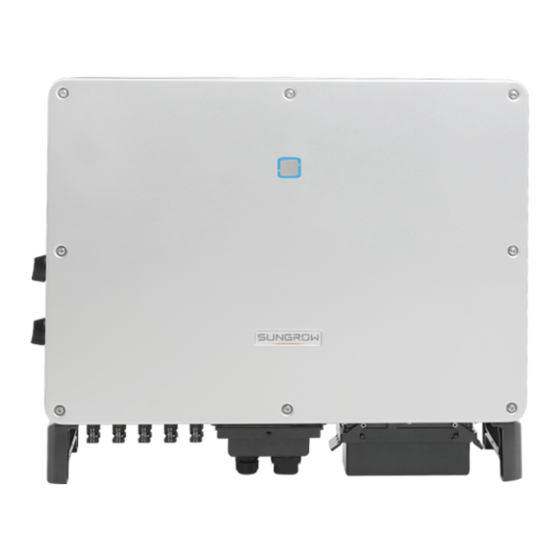
Page 16: Appearance
2 Product Introduction User Manual 2.2.2 Appearance *The image shown here is for reference only. The actual product you receive may differ. D D e e s s c c r r i i p p t t i i o o n n N N o o . -
Page 17: Dimensions
D D i i m m e e n n s s i i o o n n s s ( ( W W * * H H * * D D ) ) W W e e i i g g h h t t SG30CX 50 kg 702×595×310mm... -
Page 18: Dc Switch
2.2.5 DC Switch The DC switch is used to disconnect the DC current safely whenever necessary. The SG30CX and SG50CX sold in Australia and New Zealand are not equipped with DC switch. The SG33CX is equipped with one DC switch to control the connection and disconnection of all DC terminals. - Page 19 The communication accessory port is used to connect communication module • manufactured by SUNGROW, and upload monitoring data by means of wireless communication. The inverter can be connected to communication devices via either of the two interfaces. After communication connection is established, users can view inverter information or set inverter parameters through the iSolarCloud.
- Page 20 2 Product Introduction User Manual Before enabling the PID recovery function, make sure the voltage polarity of • the PV modules to ground meets requirement. If there are any questions, contact the PV module manufacturer or read its corresponding user manual. If the voltage scheme for the PID protection/recovery function does not meet •...
-
Page 21: Unpacking And Storage
Check the delivery scope for completeness according to the packing list. • Contact SUNGROW or the supplier in case there is any damage or incompleteness. Do not dispose of the original packing case. It is recommended to store the inverter in it. - Page 22 D D e e s s c c r r i i p p t t i i o o n n I I t t e e m m SUNGROW logo and product type Technical data of inverter Instructions and marks of conformity...
-
Page 23: Scope Of Delivery
The mounting-bracket includes 2 mounting-bracket components and 1 connecting bar. b. The SG30CX, SG33CX, SG40CX, SG50CX are respectively provided with 6, 6, 8, 10 pairs of DC connectors and cord end terminals. c. The screws include 1 M4×25 screw, 3 M4×10 screws, and 2 M6×65 screws. - Page 24 3 Unpacking and Storage User Manual The packing case should be upright. • If the inverter has been stored more than half a year, the qualified personnel should • thoroughly check and test it before using.
-
Page 25: Mechanical Mounting
Mechanical Mounting 4.1 Safety during Mounting Make sure there is no electrical connection before installation. In order to avoid electric shock or other injury, be sure there is no electricity or plumbing installations before drilling holes. Risk of injury due to improper handling Always follow the instructions when moving and positioning the inverter. -
Page 26: Carrier Requirements
4 Mechanical Mounting User Manual The ambient temperature and relative humidity must meet the following • requirements. Prevent the inverter from direct exposure to sun, rain and snow. • The inverter should be well ventilated. Ensure air circulation. • Never install the inverter in living areas. The inverter will generate noise during •... -
Page 27: Installation Clearance Requirements
User Manual 4 Mechanical Mounting In case the installation site is a level surface, mount the inverter to the horizontal-mounting bracket to meet the mounting angle requirements, as shown in the figure below. Take the following items into account when designing the bracket scheme: Consider onsite climate conditions and take anti-snow and anti-rain •... - Page 28 4 Mechanical Mounting User Manual * The distance can be shortened to 200mm according to onsite conditions. In case the distance is less than 600mm, move the inverter from the mounting-bracket or wall before maintaining fans. The distance between the bottom of the inverter and the ground surface is determined according to the bending radius of the AC cable used and the installation environment.
- Page 29 User Manual 4 Mechanical Mounting Install the inverter at an appropriate height for ease of viewing LED indicators and • operating switches.
-
Page 30: Installation Tools
4 Mechanical Mounting User Manual 4.3 Installation Tools Installation tools include but are not limited to the following recommended ones. If necessary, use other auxiliary tools on site. table 4-1 Tool specification S S p p e e c c i i f f i i c c a a t t i i o o n n N N o o . -
Page 31: Moving The Inverter
User Manual 4 Mechanical Mounting 4.4 Moving the Inverter Move the inverter to the specified position before installation. The inverter can be moved manually or via a hoist. 4.4.1 Manual Transport Lift and move the inverter to the destination by using the side handles and bottom handles. -
Page 32: Dimensions Of Mounting-Bracket
4 Mechanical Mounting User Manual step 2 Lead the sling through the two lifting rings and fasten the tie-down strap. step 3 Hoist the inverter, and stop to check for safety when the inverter is 100mm above the ground. Continue hoisting the device to the destination after ensuring the safety. step 4 Remove the lifting rings and reassemble the sealing screws released in Step 1. -
Page 33: Pv Bracket-Mounted Installation
User Manual 4 Mechanical Mounting f f i i g g u u r r e e 4 4 - - 1 1 Dimensions of mounting-bracket 4.6 PV Bracket-Mounted Installation 4.6.1 Preparation before Mounting T T o o o o l l s s S S p p e e c c i i f f i i c c a a t t i i o o n n I I t t e e m m Phillips screwdriver/ electric... - Page 34 4 Mechanical Mounting User Manual step 2 Level the assembled mounting-bracket by using the level, and mark the positions for drilling holes on the PV bracket. Drill the holes by using a hammer drill. step 3 Secure the mounting-bracket with bolts. table 4-2 Fastening sequence C C o o m m p p o o n n e e n n t t s s D D e e s s c c r r i i p p t t i i o o n n...
-
Page 35: Wall-Mounted Installation
User Manual 4 Mechanical Mounting step 5 Hoist the inverter to the installation position when necessary (refer to "4.4.2 Hoisting T T r r a a n n s s p p o o r r t t "). If the installation position is not high enough, skip performing this step. step 6 Hang the inverter to the mounting-bracket and ensure that the mounting ears perfectly engage with the mounting-bracket. -
Page 36: Mounting Steps
4 Mechanical Mounting User Manual S S p p a a r r e e p p a a r r t t s s Q Q u u a a n n t t i i t t y y S S p p e e c c i i f f i i c c a a t t i i o o n n I I t t e e m m S S o o u u r r c c e e... - Page 37 User Manual 4 Mechanical Mounting table 4-3 Fastening sequence D D e e s s i i g g n n a a t t i i o o n n D D e e s s c c r r i i p p t t i i o o n n I I t t e e m m Wall Fastening the bolt in the sequence of nut, spring washer,...
- Page 38 4 Mechanical Mounting User Manual - - - - E E n n d d...
-
Page 39: Electrical Connection
Electrical Connection 5.1 Safety Instructions Prior to any electrical connections, keep in mind that the inverter has dual power supplies. It is mandatory for the qualified personnel to wear personal protective equipments (PPE) during the electrical work. Danger to life due to a high voltage inside the inverter! The PV string will generate lethal high voltage when exposed to sunlight. -
Page 40: Electrical Connection Overview
T T e e r r m m i i n n a a l l M M a a r r k k N N o o t t e e MC4 PV connector SG30CX, SG33CX: 6 pairs of terminals PV terminals + / - SG40CX: 8 pairs of terminals SG50CX: 10 pairs of terminals For RS485 communication wiring. - Page 41 Outdoor single- The same as that of the Groundin- core copper wire PE wire in the AC cable g cable cable L1,L2,L3,N wire (SG30CX, SG33CX): 16~35 Outdoor multi- L1,L2,L3,N wire AC cable core copper or 20~50 (SG40CX): 25~50 aluminium cable...
-
Page 42: Additional Grounding Connection
5 Electrical Connection User Manual S S p p e e c c i i f f i i c c a a t t i i o o n n C C a a b b l l e e T T y y p p e e N N o o . -
Page 43: Connection Procedure
User Manual 5 Electrical Connection 5.4.2 Connection Procedure step 1 Prepare the cable and OT/DT terminal. 1:Heat shrink tubing 2:OT/DT terminal step 2 Remove the screw on the grounding terminal and fasten the cable with a screwdriver. step 3 Apply paint to the grounding terminal to ensure corrosion resistance. - - - - E E n n d d The grounding screws have been anchored to the side of the inverter before delivery, and do not need to be prepared. -
Page 44: Ac Cable Connection
M M u u l l t t i i p p l l e e I I n n v v e e r r t t e e r r s s i i n n p p a a r r a a l l l l e e l l C C o o n n n n e e c c t t i i o o n n If multiple inverters are connected in parallel to the grid, ensure that the total number of parallel inverters does not exceed 30. Otherwise, please contact SUNGROW for technical scheme. -
Page 45: Requirements For Ot/Dt Terminal
• transformer. The maximum AC current of all inverters connected in parallel must be taken into account. If more than 30 inverters are connected to the grid, contact SUNGROW. The transformer must be protected against overloading and short circuit. •... -
Page 46: Connection Procedure
5 Electrical Connection User Manual f f i i g g u u r r e e 5 5 - - 3 3 Aluminium cable terminal connection sequence Ensure that the selected terminal can directly contact with the copper bar. If there are any problems, contact the manufacturer of terminal. - Page 47 User Manual 5 Electrical Connection step 3 Strip the protection layer and insulation layer by specific length, as described in the figure below. step 4 Make the cable and crimp OT terminal. step 5 Unfasten the buckle and remove the protective cap. step 6 Secure the cable to corresponding terminals.
- Page 48 5 Electrical Connection User Manual Ensure that the depth L of the socket used is not less than 18mm. step 7 Secure the junction box, fasten the buckle, and secure it with supplied M4×10 screw. step 8 Gently pull the cable backwards to ensure firm connection, and fasten the swivel nut clockwise.
-
Page 49: Dc Cable Connection
User Manual 5 Electrical Connection - - - - E E n n d d 5.6 DC Cable Connection Electric shock! The PV array will generate lethal high voltage once exposed to sunlight. Make sure the PV array is well insulated to ground before connecting it to the inverter. -
Page 50: Connection Procedure
SG50CX 1100V 5.6.2 Connection Procedure SUNGROW provides corresponding plug connectors in the scope of delivery for quick connection of PV inputs. DC cables should be connected to the inverter via PV connectors which are included in the scope of delivery. -
Page 51: Installing The Pv Connectors
User Manual 5 Electrical Connection Use the MC4 DC terminal within the scope of delivery. Damage to the device due to the use of incompatible terminal shall not be covered by the warranty. step 1 Strip the insulation from each DC cable by 7mm. step 2 Assemble the cable ends with the crimping pliers. - Page 52 Arc or contactor over temperature may occur if the PV connectors are not firmly in place, and SUNGROW shall not be held liable for any damage caused. step 4 Follow the foregoing steps to connect PV connectors of other PV strings.
-
Page 53: Communication Junction Box
User Manual 5 Electrical Connection 5.7 Communication Junction Box 5.7.1 Remove the Junction Box step 1 Pull out the pin and keep it properly, remove the junction box. The pin removed is a required accessory for fixing the junction box. Store it properly and protect it against missing or deformation. -
Page 54: Communication Wiring Board
5 Electrical Connection User Manual 5.8 Communication Wiring Board The communication board of the inverter includes two layers. The upper layer communication board mainly includes RS485 communication interfaces while The lower layer communication board mainly includes DI/DO interface and DRM interface. -
Page 55: Rs485 Communication System
User Manual 5 Electrical Connection The RS485-1 terminal block and the RJ45 interface can be applied to applications where multiple inverters communicate in a daisy-chain form. A 120Ω resistor can be connected in parallel between RS485-1 A/B pins by configuring the dip switch. - Page 56 5 Electrical Connection User Manual When more than 15 inverters are connected on the same daisy chain, the inverters on two ends of the chain should be equipped with terminal resistors of 120Ω to ensure communication quality by configuring the dip switch (SW1), and the shielding layer of the communication cable should be single-point grounded.
-
Page 57: Connection Procedure(Terminal Block)
User Manual 5 Electrical Connection 5.9.3 Connection Procedure(Terminal Block) RS485 communication cables should be shielded twisted pair cables or shielded twisted pair Ethernet cables. There are three communication terminals, and the silkscreen marks are COM1/COM3/COM4. Please choose according to the actual situation. step 1 Remove the communication junction box, see "5.7.1 Remove the Junction Box". -
Page 58: Connection Procedure (Rj45 Network Port)
5 Electrical Connection User Manual step 5 Insert the terminal base into the corresponding terminal. table 5-3 Terminal definition N N o o D D e e f f i i n n i i t t i i o o n n RS485 A IN, RS485A differential signal+ RS485 A OUT, RS485A communication signal+ RS485 B IN, RS485B differential signal-... - Page 59 User Manual 5 Electrical Connection O O u u t t e e r r d d i i a a m m e e t t e e r r D D ( ( m m m m ) ) S S e e a a l l 4.5~6 6~12...
-
Page 60: Dry Contact Connection
5 Electrical Connection User Manual step 6 Install the junction box, see "5.7.2 Install the Junction Box". step 7 Pull the cable gently to make sure it is secured, tighten the swivel nut clockwise. - - - - E E n n d d 5.10 Dry Contact Connection 5.10.1 Dry Contact Function The configuration circuit board is provided with fault output dry contact and emergency... - Page 61 User Manual 5 Electrical Connection f f i i g g u u r r e e 5 5 - - 5 5 Normal open contact f f i i g g u u r r e e 5 5 - - 6 6 Normal close contact Devices connected to the relay should comply with related requirements: A A C C - - S S i i d d e e R R e e q q u u i i r r e e m m e e n n t t s s D D C C - - S S i i d d e e R R e e q q u u i i r r e e m m e e n n t t s s...
-
Page 62: Wiring Procedure
5 Electrical Connection User Manual f f i i g g u u r r e e 5 5 - - 7 7 Local stop contact f f i i g g u u r r e e 5 5 - - 8 8 Daisy chain topology RS485 daisy chain in the master-slave mode •... -
Page 63: Drm Connection
20kΩ The DRM function is only applicable to devices for Australia and New Zealand. Enable the DRM function through the iSolarCloud APP. If there are any problems, contact SUNGROW. 5.11.2 Connection Procedure step 1 Remove the communication junction box, see "5.7.1 Remove the Junction... - Page 64 5 Electrical Connection User Manual step 3 Loosen the swivel nut of the junction box and select an appropriate seal according to cable outer diameter. Lead the cable through the swivel nut, seal, and junction box successively. O O u u t t e e r r d d i i a a m m e e t t e e r r D D S S e e a a l l ( ( m m m m ) ) 4.5~6...
-
Page 65: Communication Module Connection (Optional)
- - - - E E n n d d 5.12 Communication Module Connection (optional) Connect the communication module produced by SUNGROW, such as Eye, WiFi, or E- Net to the communication accessory port. After successful connection, information such as power generation and running state of the inverter can be viewed via the APP on the phone. -
Page 66: Commissioning
Commissioning 6.1 Inspection before Commissioning Check the following items before starting the inverter: The inverter DC switch and external circuit breaker are disconnected. • The inverter should be accessible for operation, maintenance and service. • Nothing is left on the top of the inverter. •... -
Page 67: Isolarcloud App
iSolarCloud APP 7.1 Brief Introduction The iSolarCloud APP can establish communication connection to the inverter via the Bluetooth, thereby achieving near-end maintenance on the inverter. Users can use the APP to view basic information, alarms, and events, set parameters, or download logs, etc. -
Page 68: Login
7 iSolarCloud APP User Manual 7.3 Login 7.3.1 Requirements The following items should meet requirements: The AC and DC sides or the AC side of the inverter is powered-on. • The mobile phone is within 5m away from the inverter and there are no obstructions •... - Page 69 To set inverter parameters related to grid protection and grid support, contact SUNGROW to obtain the advanced account and corresponding password. step 4 If the inverter is not initialized, you will enter the quick setting screen of initialize protection parameter.
-
Page 70: Function Overview
7 iSolarCloud APP User Manual f f i i g g u u r r e e 7 7 - - 3 3 Initialization protection parameter Reset the protection parameters if the country setting is incorrect. Otherwise, fault may occur. In the European region, such as Netherlands, Sweden, Denmark, whose grid code complies with EN50549, select the parameter EN50549_1 (LV grid- connection) or EN50549_2 (MV grid-connection). -
Page 71: Home Page
User Manual 7 iSolarCloud APP f f i i g g u u r r e e 7 7 - - 4 4 APP function tree map 7.5 Home page After login, the home page is as follows:... - Page 72 7 iSolarCloud APP User Manual f f i i g g u u r r e e 7 7 - - 5 5 Home page table 7-1 Home page description D D e e s s i i g g n n a a t t i i o o n n D D e e s s c c r r i i p p t t i i o o n n N N o o .
- Page 73 User Manual 7 iSolarCloud APP D D e e s s i i g g n n a a t t i i o o n n D D e e s s c c r r i i p p t t i i o o n n N N o o .
-
Page 74: Running Information
7 iSolarCloud APP User Manual 7.6 Running Information Tap " " on the navigation bar to enter the running information screen, as shown in the following figure. f f i i g g u u r r e e 7 7 - - 6 6 Running Information The run information includes the PV information, inverter information, input and output information. -
Page 75: History Record
User Manual 7 iSolarCloud APP C C l l a a s s s s i i f f i i c c a a - - D D e e s s c c r r i i p p t t i i o o n n P P a a r r a a m m e e t t e e r r t t i i o o n n Voltage between the positive and negative... -
Page 76: Fault Alarm Records
7 iSolarCloud APP User Manual f f i i g g u u r r e e 7 7 - - 7 7 History record On "history record" screen, users can check the alarm records, power yield records and event records. 7.7.1 Fault Alarm Records Tap "... -
Page 77: Power Yields Records
User Manual 7 iSolarCloud APP f f i i g g u u r r e e 7 7 - - 9 9 Detailed fault alarm info 7.7.2 Power Yields Records User can view various energy records: power curve, daily energy histogram, daily energy histogram, monthly energy histogram, and annual energy histogram. -
Page 78: Event Records
7 iSolarCloud APP User Manual f f i i g g u u r r e e 7 7 - - 1 1 0 0 Power Curve Tap the time bar on the top of the screen to select a time segment and view the corresponding power curve. -
Page 79: Parameter Setting
User Manual 7 iSolarCloud APP f f i i g g u u r r e e 7 7 - - 1 1 1 1 More 7.8.1 Parameter Setting Tap " " to enter the parameter setting screen, as shown in the following figure. f f i i g g u u r r e e 7 7 - - 1 1 2 2 Parameter setting Tap "... - Page 80 7 iSolarCloud APP User Manual f f i i g g u u r r e e 7 7 - - 1 1 3 3 Change password The new password should consist of 6 characters, a combination of letters and digits.
-
Page 81: System Decommissioning
System Decommissioning 8.1 Disconnecting the Inverter For maintenance or other service work, the inverter must be switched off. Proceed as follows to disconnect the inverter from the AC and DC power sources. Lethal voltages or damage to the inverter will follow if otherwise. step 1 Disconnect the external AC circuit breaker and secure it against reconnection. -
Page 82: Dismantling The Inverter
8 System Decommissioning User Manual 8.2 Dismantling the Inverter Risk of burn injuries and electric shock! Do not touch any inner live parts until at least 5 minutes after disconnecting • the inverter from the utility grid and the PV input. step 1 Refer to "5 Electrical Connection"for the inverter disconnection of all cables in reverse... -
Page 83: Troubleshooting And Maintenance
APP or the LCD. 3. Check whether the cross-sectional area of the AC cable meets the requirement. 4. If the fault is not caused by the foregoing reasons and still exists, contact SUNGROW. Grid transient Generally, the inverter will be reconnected overvoltage, to the grid after the grid returns to normal. - Page 84 3. Check whether the AC cable is firmly in place. 4. If the fault is not caused by the foregoing reasons and still exists, contact SUNGROW. Generally, the inverter will be reconnected to the grid after the grid returns to normal. If the fault occurs repeatedly: 1.
- Page 85 SUNGROW. Wait for the inverter to return to normal. Disconnect the AC and DC switches, and Device anomaly reconnect the AC and DC switches 15 minutes later to restart the inverter. If the fault still exists, contact SUNGROW.
- Page 86 AC and DC cables are well insulated. 3. If the fault is not caused by the foregoing reasons and still exists, contact SUNGROW. Generally, the inverter will be reconnected to the grid after the grid returns to normal. If...
- Page 87 Wait for the inverter to return to normal. power is excessively large and out of the If the fault still exists, contact SUNGROW. normal operation range of the inverter. Generally, the inverter will be reconnected to the grid after the grid returns to normal. If the fault occurs repeatedly: 1.
- Page 88 Device anomaly reconnect the AC and DC switches 15 minutes later to restart the inverter. If the fault still exists, contact SUNGROW. Wait for the inverter to return to normal. If the fault occurs repeatedly: 1. Check whether the ISO resistance...
- Page 89 Disconnect the AC and DC switches, and Device anomaly reconnect the AC and DC switches 15 040-042 minutes later to restart the inverter. If the fault still exists, contact SUNGROW. Low ambient temperature, the ambient temperature is Stop and disconnect the inverter. Restart...
- Page 90 2. Check if the xth DC fuse is damaged. If so, replace the fuse. 3.If the fault is not caused by the foregoing reasons and still exists, contact SUNGROW. *The code 078 to code 081 are corresponding to PV 1 to PV 4 respectively.
- Page 91 Restart the inverter or clear the fault through Protection self-check the App. failure on grid side If the fault still exists, contact SUNGROW. 1. Check whether the AC cable is correctly connected. 2. Check whether the insulation between Grounding cable fault the ground cable and the live wire is normal.
- Page 92 String x reverse 532-547 2. If the fault is not caused by the foregoing connection alarm reasons and still exists, contact SUNGROW. *The code 532 to code 547 are corresponding to string 1 to string 16 respectively. 1. Check whether the corresponding module is sheltered.
-
Page 93: Maintenance
Restart the inverter only after removing the fault that impairs safety performance. As the inverter contains no component parts that can be maintained, never arbitrarily replace any internal components. For any maintenance need, please contact SUNGROW. Otherwise, SUNGROW shall not be held liable for any damage caused. -
Page 94: Routine Maintenance
9 Troubleshooting and Maintenance User Manual 9.2.1 Routine Maintenance I I t t e e m m M M e e t t h h o o d d P P e e r r i i o o d d Check the temperature and dust of the inverter. - Page 95 User Manual 9 Troubleshooting and Maintenance F F a a n n M M a a i i n n t t e e n n a a n n c c e e Stop the inverter and disconnect it from all power supplies before •...
- Page 96 9 Troubleshooting and Maintenance User Manual step 5 Reinstall the fan back to the inverter in reverse order and restart the inverter. - - - - E E n n d d...
-
Page 97: Appendix
10 Appendix 10.1 Technical Data S S G G 3 3 0 0 C C X X ( ( A A u u s s t t r r a a l l i i a a P P a a r r a a m m e e t t e e r r s s S S G G 3 3 3 3 C C X X S S G G 4 4 0 0 C C X X S S G G 5 5 0 0 C C X X... - Page 98 10 Appendix User Manual S S G G 3 3 0 0 C C X X ( ( A A u u s s t t r r a a l l i i a a P P a a r r a a m m e e t t e e r r s s S S G G 3 3 3 3 C C X X S S G G 4 4 0 0 C C X X S S G G 5 5 0 0 C C X X...
- Page 99 User Manual 10 Appendix S S G G 3 3 0 0 C C X X ( ( A A u u s s t t r r a a l l i i a a P P a a r r a a m m e e t t e e r r s s S S G G 3 3 3 3 C C X X S S G G 4 4 0 0 C C X X S S G G 5 5 0 0 C C X X...
-
Page 100: Quality Assurance
E E x x c c l l u u s s i i o o n n o o f f L L i i a a b b i i l l i i t t y y In the following circumstances, SUNGROW has the right to refuse to honor the quality guarantee: The free warranty period for the whole machine/components has expired. -
Page 101: Contact Information
The fault or damage is caused by installation, repairs, modification, or disassembly • performed by a service provider or personnel not from SUNGROW. The fault or damage is caused by the use of non-standard or non-SUNGROW • components or software. - Page 102 Sungrow Power Korea Limited Tokyo Seoul + 81 3 6262 9917 +827077191889 japanservice@jp.sungrowpower.com service@kr.sungrowpower.com Malaysia Philippines Sungrow SEA Sungrow Power Supply Co., Ltd Selangor Darul Ehsan Mandaluyong City +6019897 3360 +639173022769 service@my.sungrowpower.com service@ph.sungrowpower.com Thailand Spain SungrowThailand Co., Ltd. Sungrow Ibérica S.L.U.
- Page 103 Sungrow Power Supply Co., Ltd. Add: No.1699 Xiyou Rd.,New & High Technology Industrial Development Zone, 230088,Hefei, P. R. China. Web: www.sungrowpower.com E-mail: info@sungrow.cn Tel: +86 551 6532 7834 / 6532 7845 Specifications are subject to changes without advance notice.
Need help?
Do you have a question about the SG30CX and is the answer not in the manual?
Questions and answers