Sungrow SG250HX User Manual
Pv grid-connected inverter
Hide thumbs
Also See for SG250HX:
- User manual (103 pages) ,
- User manual (78 pages) ,
- User manual (109 pages)
Table of Contents
Advertisement
Quick Links
Advertisement
Table of Contents

Related Manuals for Sungrow SG250HX


Summary of Contents for Sungrow SG250HX
- Page 1 User Manual PV Grid-Connected Inverter SG250HX SG250HX–UEN-Ver26-202306...
-
Page 3: All Rights Reserved
Software Licenses • It is prohibited to use data contained in firmware or software developed by SUNGROW, in part or in full, for commercial purposes by any means. • It is prohibited to perform reverse engineering, cracking, or any other operations that com... -
Page 4: About This Manual
Please read this manual carefully before using the product and keep it properly at a place for easy access. All contents, pictures, marks, and symbols in this manual are owned by SUNGROW. No part of this document may be reprinted by the non-internal staff of SUNGROW without written au... - Page 5 Please carefully understand the meaning of these warning symbols to better use the manual. DANGER Indicates high-risk potential hazards that, if not avoided, may lead to death or serious injury. WARNING Indicates moderate-risk potential hazards that, if not avoided, may lead to death or serious injury.
-
Page 6: Table Of Contents
Contents All Rights Reserved......................I About This Manual......................II 1 Safety Instructions ....................1 1.1 Unpacking and Inspection..................2 1.2 Installation Safety....................2 1.3 Electrical Connection Safety.................3 1.4 Operation Safety....................4 1.5 Maintenance Safety....................5 1.6 Disposal Safety.....................6 2 Product Description .................... - Page 7 4.3 Installation Tools....................24 4.4 Moving Inverter....................25 4.4.1 Manual Transport..................26 4.4.2 Hoisting Transport..................26 4.5 Installing Mounting-bracket.................28 4.5.1 PV Bracket-Mounted Installation.............. 28 4.5.2 Wall-Mounted Installation................. 29 4.6 Installing the Inverter..................31 5 Electrical Connection ..................33 5.1 Safety Instructions....................33 5.2 Terminal Description...................35 5.3 Electrical Connection Overview................37 5.4 Crimp OT/DT terminal..................
- Page 8 5.12.2 Wiring Procedure..................67 5.13 Closing the Wiring Compartment..............67 6 Commissioning ..................... 68 6.1 Inspection Before Commissioning..............68 6.2 Commissioning Procedure..................68 7 iSolarCloud App ....................70 7.1 Brief Introduction....................70 7.2 Installing App...................... 70 7.3 Function Overview....................71 7.4 Login........................71 7.4.1 Requirements...................
- Page 9 10.1 Technical Data....................105 10.2 Wring Distance of DI Dry Contact..............106 10.3 Quality Assurance...................108 10.4 Contact Information..................108...
-
Page 10: Safety Instructions
Perform operations considering actual onsite conditions. • SUNGROW shall not be held liable for any damage caused by violation of gen eral safety operation requirements, general safety standards, or any safety in struction in this manual. -
Page 11: Unpacking And Inspection
If there are problems with the above inspection items, do not install the device and contact your distributor first. If the problem persists, contact SUNGROW in time. 1.2 Installation Safety DANGER •... -
Page 12: Electrical Connection Safety
User Manual 1 Safety Instructions 1.3 Electrical Connection Safety DANGER • Before electrical connections, please make sure that the inverter is not damaged, otherwise it may cause danger! • Before electrical connections, please make sure that the inverter switch and all switches connected to the inverter are set to "OFF", otherwise electric shock may occur! DANGER... -
Page 13: Operation Safety
1 Safety Instructions User Manual WARNING • Check the positive and negative polarity of the PV strings, and connect the PV connectors to corresponding terminals only after ensuring polarity correctness. • During the installation and operation of the inverter, please ensure that the positive or negative poles of PV strings do not short-circuit to the ground. -
Page 14: Maintenance Safety
NOTICE To avoid the risk of electric shock, do not perform any other maintenance operations beyond this manual. If necessary, contact SUNGROW for maintenance. Otherwise, the losses caused is not covered by the warranty. -
Page 15: Disposal Safety
1 Safety Instructions User Manual NOTICE • If the paint on the inverter enclosure falls or rusts, repair it in time. Otherwise, the inverter performance may be affected. • Do not use cleaning agents to clean the inverter. Otherwise, the inverter may be damaged, and the loss caused is not covered by the warranty. -
Page 16: Product Description
The inverter is only applicable to the scenarios described in the manual and cannot be used in other situations. Item Description Note Monocrystalline silicon, polycrystalline silicon and thin-film with PV strings out grounding. Inverter SG250HX Boost the low voltage from the inverter to grid-compatible medi Transformer um voltage. -
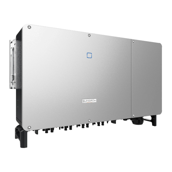
Page 17: Product Introduction
2 Product Description User Manual Item Description Note Utility grid The following figure shows the common grid configurations. 2.2 Product Introduction Model Description The model description is as follows : Appearance The following figure shows the dimensions of the inverter. The image shown here is for refer ence only. - Page 18 Dimensions The following figure shows the dimensions of the inverter. figure 2-3 Product Dimensions(in mm) Model Dimensions (W*H*D) Weight (kg) SG250HX 1051*660*363 mm 99 kg *The image shown here is for reference only. The actual product you receive may differ.
-
Page 19: Symbols On Product
2 Product Description User Manual 2.3 Symbols on Product Symbol Explanation Do not dispose of the inverter together with household waste. TÜV mark of conformity. CE mark of conformity. EU/EEA Importer. UKCA mark of conformity. Danger to life due to high voltages! Only qualified personnel can open and service the inverter. -
Page 20: Dc Switch
User Manual 2 Product Description table 2-1 LED Indicator State Description LED Color State Definition The device is connected to the grid and operating nor mally. Fast blink The Bluetooth connection is established, and there is (Period: 0.2s) data communication. No system fault occurs. -
Page 21: Circuit Diagram
2 Product Description User Manual 2.6 Circuit Diagram The following figure shows the main circuit of the inverter. figure 2-4 Circuit Diagram • DC Switches can safely disconnect the PV input when necessary to ensure the safe oper ation of the inverter and the safety of personnel. •... -
Page 22: Function Description
User Manual 2 Product Description DANGER If the lightning level exceeds the protection level of the product, surge protection and overvoltage protection may fail, resulting in electric shock and fatal injury! 2.7 Function Description The inverter is equipped with the following functions: Conversion Function The inverter converts the DC into grid-compatible AC and feeds the AC into the grid. - Page 23 2 Product Description User Manual • P-type panel When the anti-PID function is enabled, the inverter rises the potential of the negative pole of PV array of P-type panels to close to the ground potential through PID module to suppress PID effect.
- Page 24 User Manual 2 Product Description NOTICE • Before enabling anti-PID function or PID recovery function, make sure the volt age polarity of the PV modules to ground meets requirements. If there are any questions, contact the PV module manufacturer or refer to the corresponding user manual.
-
Page 25: Unpacking And Storage
• Check the scope of delivery for completeness according to the packing list. • Check the inner contents for damage after unpacking. Contact SUNGROW or the transport company in case of any damage or incompleteness, and provide photos to facilitate services. -
Page 26: Lieferumfang
User Manual 3 Unpacking and Storage 3.2 Lieferumfang 图 1: Lieferumfang a. The mounting-bracket includes 2 mounting-bracket components and 1 connecting bar. b. The screws include two M4×10, two M6×65, and four M6×14 hex socket screws. c. The two OT terminals are used for wiring power cable of the tracking system, where the wiring range is 4–6mm d. - Page 27 3 Unpacking and Storage User Manual • Store the inverter in the original packing case with the desiccant inside. • The storage temperature must be always between -40℃ and +70℃, and the storage rel ative humidity must be always between 0 and 95 %, non-condensing. •...
-
Page 28: Mechanical Mounting
4 Mechanical Mounting WARNING Respect all local standards and requirements during mechanical installation. 4.1 Safety During Mounting DANGER Make sure there is no electrical connection before installation. Before drilling, avoid the water and electricity wiring in the wall. WARNING Poor installation environment will affect system performance! •... -
Page 29: Location Requirements
• The ambient temperature and relative humidity must meet the following requirements. • Please consult SUNGROW before installing inverters outdoors in areas prone to salt dam age, which mainly are coastal areas within 500 meters of the coast. The deposition of salt... -
Page 30: Carrier Requirements
User Manual 4 Mechanical Mounting fog varies largely with nearby seawater characteristics, sea wind, precipitation, relative hu midity, terrain, and forest coverage. • It is strictly forbidden to install the inverter in an area with corrosives such as corrosive gas and organic solvent, etc. -
Page 31: Angle Requirements
Install the inverter vertically or at the maximum allowable rear tilt angle. Do not install the inverter horizontally, forward, excessively backward, sideways, or upside down. Please consult SUNGROW before tilting backwards the inverter and install it in floating power plants. - Page 32 User Manual 4 Mechanical Mounting * In case this distance is less than the distance in the diagram, move the inverter from the mounting-bracket or wall before maintaining fans. When the inverter is installed under the PV module whose supporting bracket is fixed, the distance between the top of the inverter and the top of the bracket can be reduced to 400mm.
-
Page 33: Installation Tools
4 Mechanical Mounting User Manual In case of back-to-back installation, reserve specific clearance between the two inverters. Install the inverter at an appropriate height for ease of viewing LED indicator and operating switch(es). 4.3 Installation Tools Installation tools include but are not limited to the following recommended ones. If necessary, use other auxiliary tools on site. -
Page 34: Moving Inverter
User Manual 4 Mechanical Mounting Hammer drill Pliers Marker Level (φ12, φ14) Rubber mallet Socket wrench set Open-end wrench Anti-static wrist strap (16mm) (13 mm, 16 mm) Wire cutter Wire stripper Hydraulic pliers Heat gun Crimping tool Connector wrench Multimeter RJ45 crimping tool 4–6mm ≥... -
Page 35: Manual Transport
4 Mechanical Mounting User Manual CAUTION Improper handling may cause personal injury! • Arrange an appropriate number of personnel to carry the inverter according to its weight, and installation personnel should wear protective equipment such as anti-impact shoes and gloves. •... - Page 36 User Manual 4 Mechanical Mounting step 1 Release the sealing screws on the mounting lugs and store them properly. Anchor two M12 thread lifting rings to the lugs of the inverter. step 2 Lead the sling through the two lifting rings and fasten the tie-down strap. step 3 Hoist the inverter, and stop to check for safety when the inverter is 100mm above the ground.
-
Page 37: Installing Mounting-Bracket
4 Mechanical Mounting User Manual 4.5 Installing Mounting-bracket Inverter is installed on the wall and bracket by means of mounting bracket. The dimensions of an assembled mounting-bracket are shown below. figure 4-1 Dimensions of Mounting-bracket Install the inverter to the mounting-bracket, and dimensions after installation are as follows. 4.5.1 PV Bracket-Mounted Installation... -
Page 38: Wall-Mounted Installation
User Manual 4 Mechanical Mounting step 1 Assemble the mounting-bracket. step 2 Level the assembled mounting-bracket by using the level, and mark the positions for drilling holes on the PV bracket. Drill the holes by using a hammer drill. step 3 Secure the mounting-bracket with bolts. Components Description Mounting-bracket... - Page 39 4 Mechanical Mounting User Manual step 1 Assemble the mounting-bracket. step 2 Level the assembled mounting-bracket by using the level, and mark the positions for drilling holes. step 3 Insert the expansion bolts into the holes and secure them with a rubber hammer. Fasten the nut with a wrench to expand the bolt.
-
Page 40: Installing The Inverter
User Manual 4 Mechanical Mounting Components Description Fastening the bolt in the sequence of nut, spring washer, Expansion bolt slat washer Mounting-bracket – - - End 4.6 Installing the Inverter step 1 Take out the inverter from the packing case. step 2 If the installation position is high, hoist the inverter to the position (refer to "4.4.2 Hoisting Trans... - Page 41 4 Mechanical Mounting User Manual step 4 Fix the inverter with screws. - - End...
-
Page 42: Electrical Connection
5 Electrical Connection 5.1 Safety Instructions DANGER The PV string will generate lethal high voltage when exposed to sunlight. • Operators must wear proper personal protective equipment during electrical con nections. • Must ensure that cables are voltage-free with a measuring instrument before touching DC cables. - Page 43 5 Electrical Connection User Manual WARNING • Do not damage the ground conductor. Do not operate the product in the absence of a properly installed ground conductor. Otherwise, it may cause personal injury or product damage. • Please use measuring devices with an appropriate range. Overvoltage can damage the measuring device and cause personal injury.
-
Page 44: Terminal Description
User Manual 5 Electrical Connection NOTICE • After being crimped, the OT terminal must wrap the wires completely, and the wires must contact the OT terminal closely. • When using a heat gun, protect the device from being scorched. • Before connecting a power cable (such as the AC cable, the DC cable, etc.), confirm that the label and identifier on the power cable are correct. - Page 45 5 Electrical Connection User Manual figure 5-1 Terminal Description * The image shown here is for reference only. The actual product received may differ. Item Terminal Mark Note PV terminals + / - 24, PV connector COM1 COM2 RS485 communication, digital input/output DI/ Communica...
-
Page 46: Electrical Connection Overview
User Manual 5 Electrical Connection 5.3 Electrical Connection Overview The electrical connection should be realized as follows: (A) PV string (B) Inverter (C) Utility grid (D) Monitoring device (E) AC circuit breaker table 5-1 Cable Requirements Specification Cable Type Cable Diame... - Page 47 5 Electrical Connection User Manual table 5-2 Accessory and cable requirements of the AC sealing plate Specification Accessory Cable Cable diame Cross-sectional area(m ter(mm) Four-core outdoor copper alu 30-50 L1,L2,L3: 70~240 minum cable cable* Three-core outdoor cable: L1,L2,L3: 70~240 copper alu...
- Page 48 User Manual 5 Electrical Connection * A copper to aluminum adapter terminal is required when an aluminum cable is used. For details, refer to Aluminum Cable Requirements. table 5-3 PE wire requirements PE wire cross sec Note tion The specifications are valid only when the phase wire and PE wire use the same material.
-
Page 49: Crimp Ot/Dt Terminal
5 Electrical Connection User Manual 5.4 Crimp OT/DT terminal Crimp OT/DT terminal 1. Heat shrink tubing 2. OT/DT terminal 3. Hydraulic pliers 4. Heat gun Aluminum Cable Requirements If an Aluminum cable is selected, use a copper to Aluminum adapter terminal to avoid direct contact between the copper bar and the Aluminum cable. -
Page 50: External Protective Grounding Connection
User Manual 5 Electrical Connection NOTICE Ensure that the selected terminal can directly contact with the copper bar. If there are any problems, contact the terminal manufacturer. Ensure that the copper bar is not in direct contact with the aluminum wire. Otherwise, electrochemical corrosion may occur, impairing the reliability of electrical connection. -
Page 51: External Protective Grounding Requirements
AC side grounding terminal are reliably grounded. The grounding connection can be made by other means if they are in accordance with the local standards and regulations, and SUNGROW shall not be held liable for the possible consequences. -
Page 52: Opening The Wiring Compartment
User Manual 5 Electrical Connection step 3 Apply paint to the grounding terminal to ensure corrosion resistance. The grounding screws have been anchored to the side of the inverter before delivery, and do not need to be prepared. There are two grounding terminals. Use one of them to ground the inverter. - - End 5.6 ... -
Page 53: Ac Cable Connection
5 Electrical Connection User Manual 5.7 AC Cable Connection 5.7.1 AC-Side Requirements Only with the permission of the local grid department, the inverter can be connected to the grid. Before connecting the inverter to the grid, ensure the grid voltage and frequency comply with requirements, for which, refer to "Technical Date". - Page 54 • The apparent power of the inverter should never exceed the power of the transformer. The maximum AC current of all inverters connected in parallel must be taken into account. If more than 15 inverters are connected to the grid, contact SUNGROW. • The transformer must be protected against overloading and short circuit.
-
Page 55: Requirements For Ot/Dt Terminal
5 Electrical Connection User Manual inet needs to be insulated. A third-party test report of the circuit-breaking performance of the whole machine in an event of a short-circuit on the LV side is also required. It is recommended to adopt graduated protection to ensure that in an event of a single short-circuit fault on the LV side of the box, the corresponding branch MCCB trips nor... -
Page 56: Connection Procedure
User Manual 5 Electrical Connection • Specification: M12; • Dimensions: a≤46 mm / 13 mm≤b≤15.5 mm / c≤22 mm OT/DT Terminal of PE Wire • Specification: M8/M10 . 5.7.3 Connection Procedure step 1 Open the wiring compartment. For details, refer to5.6 Opening the Wiring Compartment. - Page 57 5 Electrical Connection User Manual step 6 Make the cable and crimp OT/DT terminal. step 7 Secure the wires to corresponding terminals. Ensure that the depth L of the socket used is not less than 28mm. step 8 Gently pull the cable backwards to ensure firm connection, and fasten the swivel nut clockwise.
- Page 58 User Manual 5 Electrical Connection If the PE cable is an independent single-core cable, it is inserted into the cabinet through the standby grounding terminal. step 9 Install the protection cover. - - End...
-
Page 59: Dc Cable Connection
5 Electrical Connection User Manual 5.8 DC Cable Connection DANGER The PV string will generate lethal high voltage when exposed to sunlight. • Respect all safety instructions listed in relevant documents about PV strings. WARNING • Make sure the PV array is well insulated to ground before connecting it to the inverter. -
Page 60: Pv Input Configuration
User Manual 5 Electrical Connection NOTICE The following requirements about PV string connection must be met. Otherwise, it may cause irreversible damage to the inverter, which is not covered by the warranty. • Mixed use of PV modules of different brands or models in one MPPT circuit, or PV modules of different orientation or inclination in a string may not damage inverter, but will cause system bad performance! 5.8.1 PV Input Configuration... -
Page 61: Y Terminal Connection
5 Electrical Connection User Manual 5.8.2 Y Terminal Connection Physical Reference Drawing figure 5-3 Y Terminal /Y Terminal + Inline Fuse/Inline Fuse/Con nector Physical Drawing(Pictures are for Reference Only) Y Terminal and Inline Fuse Applications Case 1:When the Y terminal is connected at the module side, a special PV cable shall be used for connection between the Y terminal and the inverter. -
Page 62: Assembling Pv Connectors
• The Y-branch connector can be connected at the module side or the inverter side. • Sungrow provides Y-branch connector of Bizlink, whose terminal is MC4-Evo2. When it is connected at the inverter side, the Y-branch connector can be directly connected to the inverter. - Page 63 • If the cross-sectional area of the DC cable is 10mm , users need to prepare the PV connector by themselves or order it from SUNGROW. The recommended model of the female cable connector is PV-KBT4-EVO 2 / 10II-UR (Stäubli), and the recom...
- Page 64 User Manual 5 Electrical Connection step 4 Tighten the cable gland and the insulator. Cross-sectional area (mm Tightening torque (N∙m) step 5 Check for polarity correctness. NOTICE If the PV polarity is reversed, the inverter will be in a fault or alarm state and will not operate normally.
-
Page 65: Installing Pv Connector
5 Electrical Connection User Manual Do not bottom out the capnut. 5.8.4 Installing PV Connector step 1 Ensure that the DC switch is in "OFF" position. Otherwise, manually turn it to "OFF". step 2 Check the cable connection of the PV string for polarity correctness and ensure that the open circuit voltage in any case does not exceed the inverter input limit of 1,500 V. -
Page 66: Wiring Of Tracking System Power Cable (Optional)
User Manual 5 Electrical Connection NOTICE The multimeter must have a DC voltage range of at least 1500 V. If the voltage is a negative value, the DC input polarity is incorrect. Please correct the DC input polarity. If the voltage is greater than 1500 V, too many PV modules are configured to the same string. - Page 67 5 Electrical Connection User Manual Outer diameter D(mm) Seal 4.5 ~ 6 6 ~ 12 a + b 12 ~ 18 step 3 Remove the protection cover and store the released screws properly. step 4 Strip the protection layer and insulation layer by specific length, as described in the figure below. step 5 Install the OT terminal and press it tight.
- Page 68 User Manual 5 Electrical Connection DANGER Ensure that OT terminals of the power cable are installed on the OT/DT terminals of the AC cable. Otherwise, it will cause over heat or even burn. 1: OT/DT terminal of an AC cable 2: Power cable for tracking system step 7 Gently pull the cable backwards to ensure firm connection, and fasten the swivel nut clockwise.
-
Page 69: Rs485 Connection
5 Electrical Connection User Manual step 8 Install the protection cover. - - End There are four communication terminals COM1, COM2, COM3 and COM4 on the bottom of the inverter. Select the communication terminal according to onsite con ditions. Disconnector (≥ 800Vac) and fuse (16A, gM) should be installed between the inverter and the tracking system control cabinet. -
Page 70: Rs485 Communication System
User Manual 5 Electrical Connection *The reserved port is not available for the time being. The inverter is equipped with two sets of RS485 communication terminals: RS485_1 port and RS485_2 port. The port RS485_1 is used to connect Logger, so as to implement data exchange with PC or other monitoring devices. - Page 71 5 Electrical Connection User Manual figure 5-4 Single-inverter Connection Multi-inverter Communication System In case of multiple inverters, all the inverters can be connected via RS485 cables in the daisy chain manner. The communication cable of the tracking system can be connected to the port RS485_2 of any inverter in the daisy chain.
-
Page 72: Connection Procedure(Terminal Block)
User Manual 5 Electrical Connection figure 5-6 Configuration of Dip Switch (N≥15) The length of the RS485 cable and twisted pair cable should be no longer than 1,200m. If multiple inverters are connected to the data collectorLogger3000, the number of permissible daisy chains and the number of devices allowed to be connected should meet the requirements (refer to the user manual for the Logger3000). - Page 73 5 Electrical Connection User Manual Outer Diameter D(mm) Seal 4.5~6 6~12 12~18 step 3 Secure the cable to the terminal base. step 4 Insert the terminal base into the corresponding terminal. step 5 Pull the cable gently to make sure it is secured, tighten the swivel nut clockwise. - - End...
-
Page 74: Plc Communication Connection
5.11 PLC Communication Connection With a built-in PLC communication module, the inverter can communicate with the COM100A/ EMU200A (communication acquisition equipment) provided by SUNGROW. For specific wiring method, please refer to the COM100A/EMU200A user manual. • In case of PLC communication, the AC cable must be a multi-core cable instead of multiple single-core cables. - Page 75 5 Electrical Connection User Manual DO terminal (fault output dry contact):the relay can be set to fault alarm output, and user can configure it to be a normally open contact (COM&NO) or a normally closed contact (COM &NC). The relay is initially at the NC contact, and it will trip to another contact when a fault occurs. Use LED indicators or other equipment to indicate whether the inverter is in the faulty state.
-
Page 76: Wiring Procedure
User Manual 5 Electrical Connection figure 5-9 Local Stop Contact When wiring DI dry contacts, ensure that the maximum wiring distance meet the requirements 10.2 Wring Distance of DI Dry Contact. 5.12.2 Wiring Procedure Refer to the wiring of terminal block described in chapter5.10.3 Connection Procedure(Termi... -
Page 77: Commissioning
6 Commissioning 6.1 Inspection Before Commissioning Check the following items before starting the inverter: • All equipment has been reliably installed. • DC switch(es) and AC circuit breaker are in the "OFF" position. • The ground cable is properly and reliably connected. •... - Page 78 User Manual 6 Commissioning step 2 Close the AC circuit breaker between the inverter and the grid. step 3 Install the iSolarCloud App, see 7.2 Installing App for details. step 4 Set initial protection parameters via the iSolarCloud App when the inverter is connected to the grid for the first time (see Step 4 in7.4.2 Login Procedure for details).
-
Page 79: Isolarcloud App
7 iSolarCloud App 7.1 Brief Introduction The iSolarCloud App can establish communication connection to the inverter via the Bluetooth, thereby achieving near-end maintenance on the inverter. Users can use the App to view basic information, alarms, and events, set parameters, or download logs, etc. *In case the communication module Eye, WiFi or WiNet-S is available, the iSolarCloud App can also establish communication connection to the inverter via the mobile data or WiFi, thereby achieving remote maintenance on the inverter. -
Page 80: Function Overview
User Manual 7 iSolarCloud App The App icon appears on the home screen after installation. 7.3 Function Overview The App provides parameter viewing and setting functions, as shown in the following figure. figure 7-1 App Function Tree Map 7.4 Login 7.4.1 Requirements The following requirements should be met: •... -
Page 81: Login Procedure
7 iSolarCloud App User Manual 7.4.2 Login Procedure step 1 Open the App to enter the login page, tap Local Access at the bottom of the page to go to the next page. step 2 Establish the Bluetooth connection by either of the two following ways. If the LED indicator flashes blue, the connection is successfully established. - Page 82 User Manual 7 iSolarCloud App figure 7-2 Bluetooth Connection step 3 Enter the identity verification interface after the Bluetooth connection is established.
- Page 83 To set inverter parameters related to grid protection and grid support, contact your dis tributor to obtain the advanced account and corresponding password. If the distributor is unable to provide the required information, contact SUNGROW. step 4 If the inverter is not initialized, you will enter the quick setting interface of initializing protection parameters.
-
Page 84: Home
User Manual 7 iSolarCloud App In the European region, such as Netherlands, Sweden, and Denmark, whose grid code complies with EN50549, select the parameter EN50549_1 (LV gridconnection) or EN50549_2 (MV grid-connection). In the Brazilian region, set the country code as "Brazil". Selecting "Brazil_230" or "Brazil_240"... - Page 85 7 iSolarCloud App User Manual Designation Description Present state of the PID function. For details, refer to table PID function state 7-3 Description of PID Function State Display the PV power generation power, feed-in power, etc. The line with an arrow indicates energy flow between con Power flow chart nected devices, and the arrow pointing indicates energy flow direction.
-
Page 86: Run Information
User Manual 7 iSolarCloud App table 7-3 Description of PID Function State State Description PID recovery The inverters perform PID recovery actively. running It is detected that the ISO impedance is abnormal or the PID function can PID abnormity not work normally after the PID function is enabled. If the inverter is running abnormally, the alarm or fault icon will be displayed in the lower right corner of the inverter icon in power flow chart. -
Page 87: Records
7 iSolarCloud App User Manual Classifica Parameter Description tion MPPT x Current The input current of the x MPPT Daily Yield Monthly Yield Annual Yield Total Active Power Current active power value of the inverter Total Reactive Power Current reactive power value of the inverter Total Apparent Power Current apparent power value of the inverter Total Power Factor... - Page 88 User Manual 7 iSolarCloud App figure 7-7 Fault Alarm Record to select a time segment and view corresponding records. The inverter can record up to 400 latest entries. Select one of the records in the list and tap the record to view the detailed fault information as shown in following figure.
- Page 89 7 iSolarCloud App User Manual figure 7-9 Power Curve The App displays power generation records in a variety of forms, including daily power gen eration histogram,, monthly power generation histogram, annual power generation histogram and total power generation histogram. table 7-5 Yield Record Explanation Parameter Description Show the power output from 5 am to 11 pm in a single day.
-
Page 90: More
User Manual 7 iSolarCloud App 7.8 More Tap More on the navigation bar to enter the corresponding interface, as shown in the following figure. figure 7-10 More 7.8.1 System Parameters Tap Settings > System Parameters to enter the corresponding interface, as shown in the following figure. -
Page 91: Operation Parameters
7 iSolarCloud App User Manual 7.8.2 Operation Parameters Running Time Tap Settings > Operation Parameters > Running Time to enter the corresponding interface. figure 7-12 Running Time PID Parameters Tap Settings > Operation Parameters > PID Parameters to enter the corresponding inter face. -
Page 92: Power Regulation Parameters
User Manual 7 iSolarCloud App 7.8.3 Power Regulation Parameters Active Power Regulation Tap Settings > Power Regulation Parameters > Active Power Regulation to enter the screen, as shown in the following figure. figure 7-14 Active Power Regulation table 7-7 Active Power Regulation Definition/Setting Descrip... - Page 93 7 iSolarCloud App User Manual Definition/Setting Descrip Parameter Range tion Active power limit The switch for limiting output Enable/Disable power. Active power limit ratio The ratio of limiting output pow 0%~100% er to rated power in percentage. Shutdown when active Switch used determine...
- Page 94 User Manual 7 iSolarCloud App Definition/Setting Descrip Parameter Range tion Reactive power regula Switch for enabling/disabling re Enable/Disable tion active response function. Reactive power regula Ends time of reactive response. 0.1s~600.0s tion time Q(P)Curve Select the corresponding curve Curve A/Curve B/Curve C* according to local regulations QP_P1 Output power at P1 on the Q(P)
- Page 95 7 iSolarCloud App User Manual Definition/Setting Descrip Parameter Range tion QU_Q1 Pre-set proportion of reactive [-60.0%-0]* Overload power according to the grid volt Rate/1000 age U1 QU_V2 Pre-set grid voltage U2 that is 80.0%~100.0% reactive according to the grid voltage. QU_Q2 Pre-set proportion of reactive [-60.0%-60.0%]*...
-
Page 96: Communication Parameters
User Manual 7 iSolarCloud App figure 7-16 Q(U) Curve figure 7-17 Q(P) Curve 7.8.4 Communication Parameters Serial Port Parameters Tap Settings > Communication Parameters > Serial Port Parameters to enter the corre sponding interface, as shown in the following figure. figure 7-18 Serial Port Parameters table 7-9 Serial Port Parameters Parameter... -
Page 97: Firmware Update
7 iSolarCloud App User Manual figure 7-19 MPLC Parameters table 7-10 MPLC Parameters Parameter Range Band Num Band1, Band2 Array ID 1–255 Winding ID 1–10 7.8.5 Firmware Update To avoid download failure due to poor on-site network signal, it is recommended to download the firmware package to the mobile device in advance. -
Page 98: Password Changing
User Manual 7 iSolarCloud App step 8 Tap the upgrade package file, a prompt box will pop up asking you to upgrade the firmware with the file, tap CONFIRM to perform the firmware upgrade. step 9 Wait for the file to be uploaded. When the upgrade is finished, the interface will inform you of the upgrade completion. -
Page 99: System Decommissioning
8 System Decommissioning 8.1 Disconnecting Inverter CAUTION Danger of burns! Even if the inverter is shut down, it may still be hot and cause burns. Wear protective gloves before operating the inverter after it cools down. For maintenance or other service work, the inverter must be switched off. Proceed as follows to disconnect the inverter from the AC and DC power sources. -
Page 100: Disposal Of Inverter
User Manual 8 System Decommissioning • Before dismantling the inverter, disconnect the inverter from both AC and DC power sources. • If there are more than two layers of inverter DC terminals, dismantle the outer DC connectors before dismantling the inner ones. •... - Page 101 8 System Decommissioning User Manual NOTICE Some parts of the inverter may cause environmental pollution. Please dispose of them in accordance with the disposal regulations for electronic waste applicable at the in stallation site.
-
Page 102: Troubleshooting And Maintenance
App or the LCD. Modify the overvoltage protection values with the consent of the local electric power operator. 3. Contact Sungrow Customer Service if the pre ceding causes are ruled out and the fault persists. Generally, the inverter will be reconnected to the grid after the grid returns to normal. - Page 103 2. Check whether the protection parameters are appropriately set via the App or the LCD. 3. Contact Sungrow Customer Service if the pre ceding causes are ruled out and the fault persists. Generally, the inverter will be reconnected to the grid after the grid returns to normal.
- Page 104 App or the LCD. 3. Contact Sungrow Customer Service if the pre ceding causes are ruled out and the fault persists. 1. Check whether the corresponding string is of re...
- Page 105 Alarm PV string and inverter DC input) is damaged. If so, replace the fuse. 4. Contact Sungrow Customer Service if the pre ceding causes are ruled out and the alarm persists. *The code 548 to code 563 are corresponding to string 1 to string 16 respectively.
- Page 106 If so, replace the damaged ca ble and secure terminals to ensure a reliable con nection. 5. Contact Sungrow Customer Service if the pre ceding causes are ruled out and the fault persists. 1. Check whether the AC cable is correctly con...
- Page 107 2. Reconnect the communication cable of the me Alarm ter. 3. Contact Sungrow Customer Service if the pre ceding causes are ruled out and the alarm persists. 1. Check whether the output port is connected to actual grid. Disconnect it from the grid if so.
- Page 108 635–638, 900, when necessary. 901, 910, 911, 3. If the fault persists, please contact Sungrow Power Customer Service. 1. Check whether the corresponding string is of re verse polarity. If so, disconnect the DC switch and adjust the polarity when the string current drops...
- Page 109 DC side current drops below 0.5 A. 3. It is prohibited to power up the inverter again. Please contact Sungrow Customer Service. Contact SUNGROW if the measures listed in the “Troubleshooting Method” col umn have been taken but the problem persists.
-
Page 110: Maintenance
As the inverter contains no component parts that can be maintained, never open the enclosure, or replace any internal components. To avoid the risk of electric shock, do not perform any other maintenance operations beyond this manual. If necessary, contact SUNGROW for maintenance. Otherwise, the losses caused is not covered by the warranty. -
Page 111: Routine Maintenance
9 Troubleshooting and Maintenance User Manual NOTICE Touching the PCB or other static sensitive components may cause damage to the device. • Do not touch the circuit board unnecessarily. • Observe the regulations to protect against electrostatic and wear an anti-static wrist strap. - Page 112 User Manual 9 Troubleshooting and Maintenance DANGER • Power off the inverter and disconnect it from all power supplies before maintaining fans. • After the inverter is powered off for 5 minutes, measure the voltage and current with professional instrument. Only when there is no voltage nor current can oper ators who wear protective equipment operate and maintain the inverter.
- Page 113 9 Troubleshooting and Maintenance User Manual step 4 Pull out the fans, four on the left side and one on the right side. Clean them with a soft brush or vacuum cleaner, and replace them when necessary. step 5 Reinstall the fan back to the inverter in reverse order and restart the inverter. - - End...
-
Page 114: Appendix
10 A ppendix 10.1 T echnical Data Parameters SG250HX Input (DC) Max. PV input voltage 1500V Min.PV input voltage/Startup in 600V / 600V (Optional:500V / 500V) put voltage Nominal input voltage 1160V MPP voltage range 600~1500V (Optional:500~1500V) MPP voltage range for nominal... -
Page 115: Wring Distance Of Di Dry Contact
10 Appendix User Manual Parameters SG250HX AC short-circuit protection Leakage current protection Grid monitoring Ground fault monitoring DC switch / AC switch Yes / No PV string current monitoring Q at night An-ti PID and PID recovery func tion Overvoltage protection... - Page 116 User Manual 10 Appendix refers to the cable length in one direction between the DI dry contact terminal of the k inverter and the corresponding terminal of the (k-1) inverter. table 10-1 Correspondence Between Inverter Quantity and Maximum Wiring Distance Maximum Wiring Distance(unit:m) Number of In...
-
Page 117: Quality Assurance
• The customer shall give SUNGROW a reasonable period to repair the faulty device. Exclusion of Liability In the following circumstances, SUNGROW has the right to refuse to honor the quality guar antee: • The free warranty period for the whole machine/components has expired. - Page 118 User Manual 10 Appendix • Brief description of the problem • 123 For detailed contact information, please visit: https://en.sungrowpower.com/contactUS...
- Page 119 Sungrow Power Supply Co., Ltd. www.sungrowpower.com...
Need help?
Do you have a question about the SG250HX and is the answer not in the manual?
Questions and answers