Sungrow SG2.0RS-S User Manual
1-phase pv grid-connected inverter
Hide thumbs
Also See for SG2.0RS-S:
- User manual (106 pages) ,
- User manual (99 pages) ,
- User manual (117 pages)

Related Manuals for Sungrow SG2.0RS-S


Summary of Contents for Sungrow SG2.0RS-S
- Page 1 2.Qibtf!QW!Hsje.Dpoofdufe!Jowfsufs Vtfs!Nbovbm! SG2.0RS-S / SG2.5RS-S / SG3.0RS-S / SG3.0RS / SG3.6RS / SG4.0RS / SG5.0RS / SG6.0RS XXX/TVOHSPXQPXFS/DPN TH3/1.7/1ST.VFO.Wfs22.313215...
-
Page 3: All Rights Reserved
• It is prohibited to use data contained in firmware or software developed by SUNGROW, in part or in full, for commercial purposes by any means. • It is prohibited to perform reverse engineering, cracking, or any other operations that... -
Page 4: About This Manual
V V a a l l i i d d i i t t y y This manual is valid for the following inverter models: • SG2.0RS-S • SG2.5RS-S • SG3.0RS-S • SG3.0RS •... - Page 5 Indicates a hazard with a high level of risk that, if not avoided, will result in death or serious injury. Indicates a hazard with a medium level of risk that, if not avoided, could result in death or serious injury. Indicates a hazard with a low level of risk that, if not avoided, could result in minor or moderate injury.
-
Page 7: Table Of Contents
C C o o n n t t e e n n t t s s All Rights Reserved .....................I About This Manual .....................II 1 Safety ......................1 1.1 PV Panels..................... 1 1.2 Utility Grid ....................1 1.3 Inverter ......................2 2 Product Description .................. - Page 8 5.4.1 Additional Grounding Requirements..........22 5.4.2 Connection Procedure ..............22 5.5 AC Cable Connection ................. 23 5.5.1 AC Side Requirements ..............23 5.5.2 Assembling the AC Connector ............24 5.5.3 Installing the AC Connector............... 26 5.6 DC Cable Connection ................. 27 5.6.1 PV Input Configuration ..............
- Page 9 7.10.2 Operation Parameters ..............61 7.10.3 Power Regulation Parameters............61 7.10.4 Communication Parameters ............66 7.10.5 Firmware Update................66 8 System Decommissioning ..............68 8.1 Disconnecting the Inverter................68 8.2 Dismantling the Inverter................68 8.3 Disposal of the Inverter................69 9 Troubleshooting and Maintenance ............
-
Page 11: Safety
The safety instructions in this manual cannot cover all the precautions that should be followed. Perform operations considering actual onsite conditions. SUNGROW shall not be held liable for any damage caused by violation of the safety instructions in this manual. -
Page 12: Inverter
1 Safety User Manual All electrical connections must be in accordance with local and national standards. Only with the permission of the local utility grid company, the inverter can be connected to the utility grid. 1.3 Inverter Danger to life from electric shocks due to live voltage Do not open the enclosure at any time. - Page 13 User Manual 1 Safety Only qualified personnel can perform the country setting. Unauthorized alteration may cause a breach of the type-certificate marking. Risk of inverter damage due to electrostatic discharge (ESD)! By touching the electronic components, you may damage the inverter. For inverter handling, be sure to: •...
-
Page 14: Product Description
I I t t e e m m N N o o t t e e Compatible with monocrystalline silicon, polycrystalline PV strings silicon, and thin-film modules without grounding. SG2.0RS-S, SG2.5RS-S, SG3.0RS-S, SG3.0RS, SG3.6RS, Inverter SG4.0RS, SG5.0RS, SG6.0RS. Metering device Meter cupboard with power distribution system. -
Page 15: Product Introduction
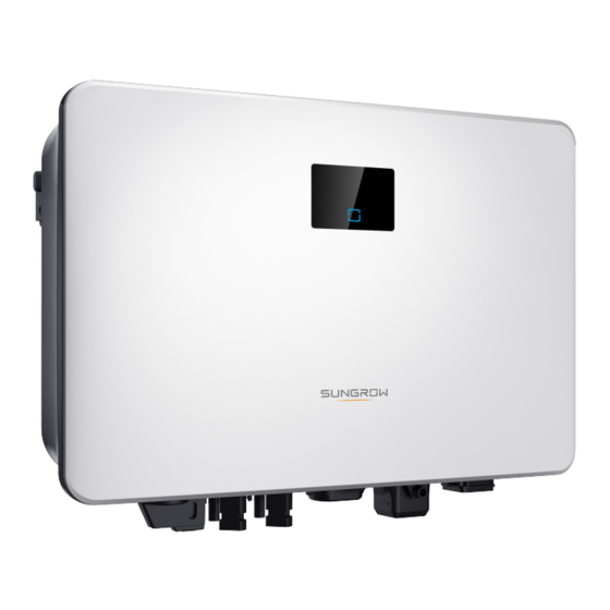
User Manual 2 Product Description D D e e s s c c r r i i p p t t i i o o n n I I t t e e m m N N o o t t e e Utility grid TT,TN-C,TN-S, TN-C-S. - Page 16 2 Product Description User Manual F F i i g g u u r r e e 2 2 - - 2 2 Inverter Appearance D D e e s s c c r r i i p p t t i i o o n n N N o o .
-
Page 17: Symbols On The Product
W W ( ( m m m m ) ) H H ( ( m m m m ) ) D D ( ( m m m m ) ) SG2.0RS-S, SG2.5RS-S, SG3.0RS-S SG3.0RS, SG3.6RS, SG4.0RS, SG5.0RS, SG6.0RS 2.3 Symbols on the Product... -
Page 18: Led Panel
2 Product Description User Manual S S y y m m b b o o l l E E x x p p l l a a n n a a t t i i o o n n Burn danger due to the hot surface that may exceed 60℃. Danger to life due to high voltages! Do not touch live parts for 10 minutes after disconnection from the power sources. -
Page 19: Circuit Diagram
User Manual 2 Product Description Table 2-1 State description of the LED indicator L L E E D D c c o o l l o o r r S S t t a a t t e e D D e e f f i i n n i i t t i i o o n n The inverter is operating normally. -
Page 20: Function Description
After communication connection is established, users can view inverter information, operational data and can set inverter parameters through the iSolarCloud. It is recommended to use the communication module from SUNGROW. Using a device from other companies may lead to communication failure or other unexpected damage. - Page 21 User Manual 2 Product Description E E x x p p o o r r t t P P o o w w e e r r L L i i m m i i t t Set the export power limit value via iSolarCloud App. When the smart energy meter detects that the export power is greater than the limit value, the inverter will reduce the output power within the specified range.
-
Page 22: Unpacking And Storage
• Check the scope of delivery for completeness according to the packing list. • Check the inner contents for damage after unpacking. Contact SUNGROW or the transport company in case of any damage or incompleteness, and provide photos to facilitate services. -
Page 23: Mechanical Mounting
Mechanical Mounting 4.1 Safety during Mounting Make sure there is no electrical connection before installation. In order to avoid electric shock or other injury, make sure that holes will not be drilled over any electricity or plumbing installations. Risk of injury due to improper handling •... -
Page 24: Carrier Requirements
4 Mechanical Mounting User Manual • The ambient temperature and relative humidity must meet the following requirements. • Avoid direct exposure to sun, rain and snow. • The inverter should be well ventilated. Ensure air circulation. • Never install the inverter in living areas. The inverter will generate noise during operation, affecting daily life. -
Page 25: Clearance Requirements
User Manual 4 Mechanical Mounting 4.2.4 Clearance Requirements Reserve enough clearance around the inverter to ensure sufficient space for heat dissipation. Install the inverter at an appropriate height for ease of viewing the screen and LED indicator and operating switch(es). 4.3 Installation Tools Installation tools include but are not limited to the following recommended ones. - Page 26 4 Mechanical Mounting User Manual Table 4-1 Tool specification Earplugs Dust mask Protective gloves Goggles Insulated shoes Utility knife Marker Wrist strap Wire cutter Wire stripper Hydraulic plier Rubber mallet Hammer drill Phillips screwdriver Electric screwdriver Wrench (33 mm, (φ10) (M4, M6) (M4, M6) 35 mm)
-
Page 27: Moving The Inverter
User Manual 4 Mechanical Mounting MC4 terminal Tube terminal crimping tool (0.5 crimping tool (4 –6 mm –1.0 mm 4.4 Moving the Inverter Before installation, remove the inverter from the packing case and move it to the installation site. Follow the instructions below as you move the inverter: •... - Page 28 4 Mechanical Mounting User Manual Step 2 Place the expansion tubes into the holes. Then secure the wall-mounting bracket to the wall firmly with the expansion bolt sets. Step 3 Lift the inverter and slide it down along the wall-mounting bracket to make sure they match perfectly.
-
Page 29: Electrical Connection
Electrical Connection 5.1 Safety Instructions Prior to any electrical connections, keep in mind that the inverter has dual power supplies. It is mandatory for the qualified personnel to wear personal protective equipments (PPE) during the electrical work. Danger to life due to a high voltage inside the inverter! •... - Page 30 5 Electrical Connection User Manual F F i i g g u u r r e e 5 5 - - 1 1 Terminals (SG3.0RS for example) * The image shown here is for reference only. The actual product received may differ. Table 5-1 Terminal Description D D e e c c i i s s i i v v e e D D e e s s c c r r i i p p t t i i o o n n...
-
Page 31: Electrical Connection Overview
User Manual 5 Electrical Connection D D e e s s c c r r i i p p t t i i o o n n L L a a b b e e l l For external Demand Response Enabling Device R, C ("AU"/"NZ") RSD-1, RSD-2... -
Page 32: Additional Grounding Connection
• The ground connection of this additional grounding terminal cannot replace the connection of the PE terminal of the AC cable. Make sure those terminals are both grounded reliably. SUNGROW shall not be held liable for any damage caused by the violation. -
Page 33: Ac Cable Connection
User Manual 5 Electrical Connection (1) Heat shrink tubing (2) OT/DT terminal Step 2 Remove the screw on the grounding terminal and fasten the cable with a screwdriver. Step 3 Apply paint to the grounding terminal to ensure corrosion resistance. - - - - E E n n d d 5.5 AC Cable Connection 5.5.1 AC Side Requirements... -
Page 34: Assembling The Ac Connector
R R e e c c o o m m m m e e n n d d e e d d S S p p e e c c i i f f i i c c a a t t i i o o n n I I n n v v e e r r t t e e r r M M o o d d e e l l SG2.0RS-S/SG2.5RS-S/SG3.0RS-S 25 A SG3.0RS/SG3.6RS/SG4.0RS/SG5.0RS... - Page 35 User Manual 5 Electrical Connection Step 2 Thread the AC cable of appropriate length through the swivel nut, the sealing ring and the housing. Step 3 Remove the cable jacket by less than 45 mm, and strip the wire insulation by 12 mm– 16 mm.
-
Page 36: Installing The Ac Connector
5 Electrical Connection User Manual Observe the plug assignment. • Do not connect the L line to the "PE" terminal or the PE wire to the "N" terminal. Otherwise, unrecoverable damage to the inverter may follow. • Do not connect the L line and the N line in reverse, otherwise the inverter may not operate normally. -
Page 37: Dc Cable Connection
MPPT operating voltage range, namely, 40 V to 560 V. 5.6.1 PV Input Configuration • The inverters SG2.0RS-S / SG2.5RS-S / SG3.0RS-S have one PV input with one MPP tracker. • The inverters SG3.0RS / SG3.6RS / SG4.0RS / SG5.0RS / SG6.0RS have two PV inputs, each with independent MPP tracker. -
Page 38: Assembling The Pv Connectors
• Ensure all cables are voltage-free before performing electrical operations. • Do not connect the AC circuit breaker before finishing electrical connection. SUNGROW provides corresponding PV connectors in the scope of delivery for quick connection of PV inputs. To ensure IP65 protection, use only the supplied connector or the connector with the same ingress of protection. -
Page 39: Installing The Pv Connectors
User Manual 5 Electrical Connection 1: Positive crimp contact 2:Negative crimp contact Step 3 Lead the cable through cable gland, and insert the crimp contact into the insulator until it snaps into place. Gently pull the cable backward to ensure firm connection. Tighten the cable gland and the insulator (torque 2.5 N.m to 3 N.m). - Page 40 PV connectors to corresponding terminals only after ensuring polarity correctness. • Electric arc or contactor overtemperature may occur if the PV connectors are not firmly in place, and SUNGROW shall not be held liable for any damage caused due to this operation.
-
Page 41: Winet-S Connection
User Manual 5 Electrical Connection Step 4 Seal the unused PV terminals with the terminal caps. - - - - E E n n d d 5.7 WiNet-S Connection The WiNet-S module supports Ethernet communication and WLAN communication. It is not recommended to use both communication methods at the same time. - Page 42 5 Electrical Connection User Manual Step 3 Unscrew the housing from the communication module. Step 4 Thread the network cable through the swivel nut and gasket. Afterwards, route the cable into the opening of the sealing. Finally, insert the cable through the housing. Step 5 Insert the RJ45 plug into the front plug connector until there is an audible click and tighten the housing.
-
Page 43: Wlan Communication
User Manual 5 Electrical Connection Step 6 Remove the waterproof lid from the C C O O M M 1 1 terminal and install WiNet-S. Step 7 Slightly shake it by hand to determine whether it is installed firmly. - - - - E E n n d d 5.7.2 WLAN Communication Step 1 Remove the waterproof lid from the C C O O M M 1 1 terminal. - Page 44 5 Electrical Connection User Manual Step 2 Remove the seal and lead the cable through the cable gland. Step 3 Remove the cable jacket and strip the wire insulation. Step 4 (Optional) When using a multi-core multi-strand wire cable, connect the wire head to the cord end terminal.
-
Page 45: Drm Connection
User Manual 5 Electrical Connection Step 6 Insert the terminal plug into the C C O O M M 2 2 terminal at the bottom side of the inverter and then install the housing. Step 7 Slightly pull out the cable and then fasten the swivel nut. Lock the connector with the screw. - Page 46 5 Electrical Connection User Manual Step 1 Unscrew the swivel nut from the communication connector. Step 2 Remove the seal and lead the cable through the cable gland. Step 3 Remove the cable jacket and strip the wire insulation. Step 4 (Optional) When using a multi-core multi-strand wire cable, connect the wire head to the cord end terminal.
- Page 47 User Manual 5 Electrical Connection Step 5 Plug the wires into the corresponding terminals as shown in the following figure. Ensure that the wires are securely in place by slightly pulling them. Step 6 Insert the terminal plug into the C C O O M M 2 2 terminal at the bottom side of the inverter and then install the housing.
- Page 48 5 Electrical Connection User Manual Step 7 Slightly pull out the cable and then fasten the swivel nut. Lock the connector with the screw. - - - - E E n n d d...
-
Page 49: Commissioning
Step 1 Install the iSolarCloud App with latest version. Refer to "7.2 Installing the App". Step 2 Register an account. Refer to "7.3 Account Registration". If you have got the account and password from the distributor/installer or SUNGROW, skip this step. -
Page 50: Creating A Plant
6 Commissioning User Manual Step 3 Download the firmware package to the mobile device in advance. Refer to "7.10.5 Firmware Update". This is to avoid download failure due to poor on-site network signal. - - - - E E n n d d 6.4 Creating a Plant Screenshots of creating a plant are for reference only. - Page 51 User Manual 6 Commissioning F F i i g g u u r r e e 6 6 - - 3 3 Selecting Plant/Inverter Type Step 5 Scan the QR code on the communication device or manually enter the serial number of the communication device.
-
Page 52: Initializing The Device
6 Commissioning User Manual on WiNet-S blinks quickly when this mode is turned on. Return to the App and the screen displays successful connection to the inverter WLAN. Tap N N E E X X T T . F F i i g g u u r r e e 6 6 - - 6 6 Turn on EasyConnect Mode The EasyConnect mode can be used only when the router is 2.4 GHz. - Page 53 User Manual 6 Commissioning F F i i g g u u r r e e 6 6 - - 8 8 Upgrade Reminder Step 2 After download, it would take around 15 minutes to update. After successful upgrade, the screen will show the version numbers before and after the upgrade as well as the upgrade time.
- Page 54 6 Commissioning User Manual The parameter C C o o u u n n t t r r y y / / R R e e g g i i o o n n must be set to the country (region) where the inverter is installed at.
-
Page 55: Configuring The Plant
User Manual 6 Commissioning N N e e t t w w o o r r k k S S e e r r v v i i c c e e P P r r o o v v i i d d e e r r G G r r i i d d T T y y p p e e •... - Page 56 6 Commissioning User Manual F F i i g g u u r r e e 6 6 - - 1 1 1 1 Display the Added Inverter Step 2 Fill in the plant information. The fields marked with * must be filled in. F F i i g g u u r r e e 6 6 - - 1 1 2 2 Entering Plant Information Step 3 ( ( O O p p t t i i o o n n a a l l ) ) Fill in the tariff information.
- Page 57 User Manual 6 Commissioning F F i i g g u u r r e e 6 6 - - 1 1 3 3 Entering Tariff Information Step 4 Fill in the end user's e-mail address. The first time you fill in the end user's e-mail address, the system will create an account for the end user and send an email to the end user.
- Page 58 F F i i g g u u r r e e 6 6 - - 1 1 6 6 Live Data View Function Setting Consult Sungrow service for the devices that support live data function. Step 7 Tab B B A A C C K K to the C C O O M M P P L L E E T T E E D D screen. Tab P P D D F F R R E E P P O O R R T T to export the plant...
- Page 59 User Manual 6 Commissioning Step 8 Tab B B A A C C K K to the C C O O M M P P L L E E T T E E D D screen. Tab D D A A S S H H B B O O A A R R D D to return and manually refresh the page until the newly created plant is displayed with status commissioned.
-
Page 60: Isolarcloud App
Users can also view inverter information and set parameters through the App. * To achieve direct login via WLAN, the wireless communication module developed and manufactured by SUNGROW is required. The iSolarCloud App can also establish communication connection to the inverter via Ethernet connection. -
Page 61: Account Registration
User Manual 7 iSolarCloud App 7.3 Account Registration The account distinguishes two user groups, end user and distributor/installer. • The end user can view plant information, create plants, set parameters, share plants, etc. • The distributor/installer can help the end user to create plants, manage, install, or maintain plants, and manage users and organizations. -
Page 62: Login
7 iSolarCloud App User Manual The code of upper level distributor/installer can be obtained from the upper level distributor/installer. Only when your organization belongs to the upper level distributor/installer organization, can you fill in the corresponding code. Step 4 Tick A A c c c c e e p p t t p p r r i i v v a a c c y y p p r r o o t t o o c c o o l l and tap R R e e g g i i s s t t e e r r to finish the registration operation. - - - - E E n n d d 7.4 Login 7.4.1 Requirements... - Page 63 User Manual 7 iSolarCloud App F F i i g g u u r r e e 7 7 - - 3 3 WLAN Local Access Step 5 If the inverter is not initialized, navigate to the quick setting screen to initialize the protection parameters.
-
Page 64: Initial Settings
7 iSolarCloud App User Manual - - - - E E n n d d 7.5 Initial Settings Tap C C o o u u n n t t r r y y / / R R e e g g i i o o n n and select the country where the inverter is installed. For countries except Australia and Germany, the initialization is completed. -
Page 65: Home
User Manual 7 iSolarCloud App F F i i g g u u r r e e 7 7 - - 5 5 App Key Function Menu 7.7 Home Home page of the App is shown in the following figure. -
Page 66: Run Information
7 iSolarCloud App User Manual F F i i g g u u r r e e 7 7 - - 6 6 Home Table 7-1 Home Page Description D D e e s s c c r r i i p p t t i i o o n n N N o o . -
Page 67: Records
User Manual 7 iSolarCloud App Table 7-2 Description of Run Information D D e e s s c c r r i i p p t t i i o o n n I I t t e e m m Shows voltage and current of every PV string. - Page 68 7 iSolarCloud App User Manual F F i i g g u u r r e e 7 7 - - 8 8 Chart The App displays power generation records in a variety of forms, including daily power generation graph, monthly power generation histogram, annual power generation histogram and total power generation histogram.
- Page 69 User Manual 7 iSolarCloud App F F i i g g u u r r e e 7 7 - - 9 9 Fault Alarm Record Click to select a time segment and view corresponding records. Select one of the records in the list and click the record, to view the detailed fault info as shown in following figure.
-
Page 70: More
7 iSolarCloud App User Manual F F i i g g u u r r e e 7 7 - - 1 1 1 1 Event Record Click to select a time segment and view corresponding records. 7.10 More Tap M M o o r r e e on the navigation bar to enter the corresponding screen, as shown in the following figure. -
Page 71: Operation Parameters
User Manual 7 iSolarCloud App F F i i g g u u r r e e 7 7 - - 1 1 3 3 System Parameters B B o o o o t t / / S S h h u u t t d d o o w w n n Tap B B o o o o t t / / S S h h u u t t d d o o w w n n to send the boot/shutdown instruction to the inverter. - Page 72 7 iSolarCloud App User Manual F F i i g g u u r r e e 7 7 - - 1 1 5 5 Active Power Regulation Table 7-4 Description of Active Power Regulation Parameters D D e e s s c c r r i i p p t t i i o o n n R R a a n n g g e e P P a a r r a a m m e e t t e e r r Switch for activating/deactivating the...
- Page 73 User Manual 7 iSolarCloud App F F i i g g u u r r e e 7 7 - - 1 1 6 6 Reactive Power Regulation Table 7-5 Description of Reactive Power Regulation Parameters D D e e s s c c r r i i p p t t i i o o n n R R a a n n g g e e P P a a r r a a m m e e t t e e r r Switch for activating/deactivating the...
- Page 74 7 iSolarCloud App User Manual Table 7-6 "Q(P)" Mode Parameters Explanation P P a a r r a a m m e e t t e e r r E E x x p p l l a a n n a a t t i i o o n n R R a a n n g g e e Q(P) Curve Select corresponding curve according to local...
- Page 75 User Manual 7 iSolarCloud App The reactive power output of the inverter varies in response to the grid voltage. Table 7-7 "Q(U)" Mode Parameter Explanation E E x x p p l l a a n n a a t t i i o o n n R R a a n n g g e e P P a a r r a a m m e e t t e e r r Select corresponding curve according to local...
-
Page 76: Communication Parameters
7 iSolarCloud App User Manual F F i i g g u u r r e e 7 7 - - 1 1 8 8 Reactive Power Regulation Curve in Q(U) Curve 7.10.4 Communication Parameters Tap S S e e t t t t i i n n g g s s → → C C o o m m m m u u n n i i c c a a t t i i o o n n P P a a r r a a m m e e t t e e r r s s to enter the corresponding screen, as shown in the following figure. - Page 77 User Manual 7 iSolarCloud App F F i i g g u u r r e e 7 7 - - 2 2 0 0 Firmware Download Step 3 Select the firmware from the file list and download. Tap D D o o w w n n l l o o a a d d e e d d to view successfully downloaded firmware package.
-
Page 78: System Decommissioning
System Decommissioning 8.1 Disconnecting the Inverter For maintenance or other service work, the inverter must be switched off. Proceed as follows to disconnect the inverter from the AC and DC power sources. Lethal voltages or damage to the inverter will follow if otherwise. Step 1 Disconnect the external AC circuit breaker and secure it against reconnection. -
Page 79: Disposal Of The Inverter
User Manual 8 System Decommissioning Step 1 Refer to "5 Electrical Connection" for the inverter disconnection of all cables in reverse steps. Step 2 Dismantle the inverter referring to "4 Mechanical Mounting" in reverse steps. Step 3 If necessary, remove the wall-mounting bracket from the wall. Step 4 If the inverter will be reinstalled in the future, please refer to "3.2 Inverter Storage"... -
Page 80: Troubleshooting And Maintenance
3. Check whether the cross-sectional area of the AC cable meets the requirement. 4. If the alarm persists, contact SUNGROW. Generally, the inverter will be reconnected to the grid after the grid recovers. If the alarm occurs frequently: 1. - Page 81 2. Check, through the App, whether the protection parameters are appropriately set. 3. If the alarm persists, contact SUNGROW. Generally, the inverter will be reconnected to the grid after the grid recovers. If the alarm occurs frequently: 1.
- Page 82 App. 3. If the alarm persists, contact SUNGROW. 1. Check whether the corresponding string is of reverse polarity. If so, disconnect the DC switch and adjust the polarity when the solar radiation is low and the string current drops below 0.5 A.
- Page 83 If the fault persists, check it again when the weather turns fine. 5. If the alarm persists, contact SUNGROW. 1. Check whether the AC cable is correctly connected.
-
Page 84: Maintenance
Meter 2. Reconnect the Smart Energy Meter communication communication cable. error 3. If the alarm persists, contact SUNGROW. The inverter can operate normally. 1. Check whether the related cable connection and terminals are abnormal, and check whether the System alarm ambient environment is abnormal. -
Page 85: Routine Maintenance
• For any maintenance need, please contact SUNGROW. Otherwise, SUNGROW shall not be held liable for any damage caused. Servicing of the device in accordance with the manual should never be undertaken in the absence of proper tools, test equipments or the latest revision of the manual which has been clearly and thoroughly understood. -
Page 86: Appendix
10 Appendix 10.1 Technical Data P P a a r r a a m m e e t t e e r r S S G G 2 2 . . 0 0 R R S S - - S S S S G G 2 2 . - Page 87 User Manual 10 Appendix P P a a r r a a m m e e t t e e r r S S G G 2 2 . . 0 0 R R S S - - S S S S G G 2 2 .
- Page 88 10 Appendix User Manual P P a a r r a a m m e e t t e e r r S S G G 2 2 . . 0 0 R R S S - - S S S S G G 2 2 .
- Page 89 User Manual 10 Appendix P P a a r r a a m m e e t t e e r r S S G G 3 3 . . 0 0 R R S S S S G G 3 3 . . 6 6 R R S S S S G G 4 4 .
- Page 90 10 Appendix User Manual P P a a r r a a m m e e t t e e r r S S G G 3 3 . . 0 0 R R S S S S G G 3 3 . . 6 6 R R S S S S G G 4 4 .
- Page 91 User Manual 10 Appendix P P a a r r a a m m e e t t e e r r S S G G 5 5 . . 0 0 R R S S S S G G 6 6 . . 0 0 R R S S 50 Hz / 45 Hz–55 Hz, 60 Hz / 55 Hz–65 Hz Nominal grid frequency / Grid frequency range...
-
Page 92: Quality Assurance
E E x x c c l l u u s s i i o o n n o o f f L L i i a a b b i i l l i i t t y y In the following circumstances, SUNGROW has the right to refuse to honor the quality guarantee: •... -
Page 93: Contact Information
A A u u s s t t r r a a l l i i a a C C h h i i n n a a ( ( H H Q Q ) ) Sungrow Power Supply Co., Ltd Sungrow Australia Group Pty. Ltd. - Page 94 M M a a l l a a y y s s i i a a P P h h i i l l i i p p p p i i n n e e s s Sungrow SEA Sungrow Power Supply Co., Ltd Selangor Darul Ehsan Mandaluyong City...
Need help?
Do you have a question about the SG2.0RS-S and is the answer not in the manual?
Questions and answers