Table of Contents
Advertisement
Quick Links
Advertisement
Table of Contents
Troubleshooting

Related Manuals for Sungrow SG2500-MV


Summary of Contents for Sungrow SG2500-MV
- Page 1 SG2500-MV MV Turnkey Station System Manual SG2500-MV_V13-SEN-Ver12-201805...
-
Page 3: Table Of Contents
Contents About This Manual ..............1 1.1 Foreword ..................... 1 1.2 Validity ......................1 1.3 Content ......................1 1.4 Target Group....................1 1.5 Symbols Explanation ................... 2 1.6 How to Use this Manual ................3 1.7 Terminology ....................3 Safety Instructions ..............4 2.1 Intended Usage ................... - Page 4 3.3 Inverter Design ..................11 3.3.1 Inverter Views ..................11 3.3.2 Mechanical Parameter ..............12 3.3.3 Internal Components ................ 13 3.3.4 Ventilation Design ................14 3.3.5 Cable Entry Design ................14 3.4 Module Design ..................15 3.4.1 Appearance of the Modules ............. 15 3.4.2 Electrical Connections Area .............
- Page 5 6.1.2 Five Safety Rules ................33 6.2 Parts for Cabling ..................34 6.2.1 Copper Wire Connection ..............34 6.2.2 Aluminum Wire Connection ............... 35 6.3 Preparation before Electrical Connections ..........36 6.3.1 Installation Tools ................36 6.3.2 Opening the Module Front Door ............36 6.3.3 Removal of the Protective Grid ............
- Page 6 7.5 Starting the Device ................... 47 7.6 LCD Parameter Setting ................48 7.7 Completing Commissioning ..............48 Starting/Stopping ..............50 8.1 Starting...................... 50 8.1.1 Inspection before starting ..............50 8.1.2 Steps to Start ..................50 8.2 Stopping ....................51 8.2.1 Normal Stop ..................51 8.2.2 Inverter Stops when A Fault Occurs ..........
- Page 7 9.13.3 Protection Parameter ..............65 10 Inverter Functions ..............68 10.1 Operation Mode ................68 10.1.1 Mode Change .................. 68 10.1.2 Operation Mode Description ............68 10.2 Active Power Limitation ..............70 10.2.1 Introduction to Active Power Limitation ........... 70 10.2.2 How to Realize Power Limitation ............
- Page 8 11.5 Other Faults ..................82 12 Routine Maintenance ............. 84 12.1 Safety Instructions ................84 12.1.1 Safety Instructions ................84 12.1.2 Five Safety Rules ................84 12.2 Maintenance ................... 85 12.2.1 Introduction..................85 12.2.2 Maintenance Interval ..............85 12.3 Cleaning the Inverter ..............87 12.3.1 Introduction..................
-
Page 9: About This Manual
1.2 Validity This manual is applicable to the MV Turnkey Station product of SG2500-MV (hereinafter it will be referred to as "inverter" unless otherwise specified). 1.3 Content... -
Page 10: Symbols Explanation
1 About This Manual System Manual Equipped with the ability to cope with the dangerous and emergency situations during installation and commissioning Familiar with the country/regional standards and specifications Familiar with this manual 1.5 Symbols Explanation This manual contains important safety and operational instructions that must be accurately understood and respected during the installation and maintenance of the equipment. -
Page 11: How To Use This Manual
All rights reserved including the pictures, markings and symbols used. Any reproduction or disclosure, even partially, of the contents of this manual is strictly forbidden without prior written authorization of Sungrow. The contents of the manual will be periodically updated or revised due to the product development. -
Page 12: Safety Instructions
2 Safety Instructions 2.1 Intended Usage The inverter, R & D and manufactured by Sungrow, is mainly applied to large-and-medium PV power inverter. The inverter integrates PV modules, transformer, and monitoring & power distribution units, and security & protection system to meet the modular design and quick installation requirement of the large-and-medium PV power inverter as well as ensure the long-time, reliable and safe grid-connected power generation. -
Page 13: General Safety Rules
System Manual 2 Safety Instructions 2.2.1 General Safety Rules Touching of the terminals or contactors connected to the grid may lead to electric shock hazards! Do not touch the terminals or conductors connected to the grid. Respect all safety instructions on the grid connection. Lethal voltages are present inside the device! ... -
Page 14: Ground Fault Protection
2 Safety Instructions System Manual Inverter is disconnected from the PV array. Necessary warning signs are in place to prevent accidental reconnection. 2.2.4 Ground Fault Protection If a ground fault occurs to the PV system, some parts that were voltage-free before may contain lethal voltage. -
Page 15: Esd Protection
System Manual 2 Safety Instructions 2.2.8 ESD Protection Devices may be damaged irreversibly by electrostatic discharge (ESD). Avoid unnecessary touching of the PCB. Observe all the ESD-related safety instructions. Take proper personal protective equipment (PPE), like wear wrist strap. 2.2.9 LCD Parameter Setting Certain LCD settable parameters are closely related to the inverter and internal devices operation, therefore these parameters can only be set after reliable evaluation of the... -
Page 16: Disposal Of Waste
This manual may not cover all possible situations. Should a specific problem occur that is not explained in this manual, please contact Sungrow. 2.3 Safety Instructions of Each Working Area The station can be divided into module room, and transformer room. To make sure the device safety and efficient operation, the above mentioned two parts are designed relatively independently. -
Page 17: Safe Operation Of The Module Room
System Manual 2 Safety Instructions 2.3.1 Safe Operation of the Module room Perform the operations in this section before any operation on the module room. Physical injury or device damage may follow if otherwise. Identify the module and read the safety instructions on the module cabinet carefully. Step 1 Step 2 Disconnect all power supplies from the module, including module upstream and... -
Page 18: Product Description
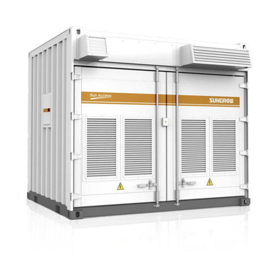
3 Product Description 3.1 Brief Introduction The inverter mainly applies to medium and large-scale PV generation systems. Based on standard-sized outdoor container, the inverter integrates the PV grid-connected inverters, transformer, power distribution unit, monitoring unit, security system and firefighting equipment to meet with the requirements of modular design and fast installation of the PV systems. -
Page 19: Inverter Design
System Manual 3 Product Description 3.3 Inverter Design 3.3.1 Inverter Views View Description Front view. Front of the inverter. The front doors of the module room transformer room located on the side of the inverter front door. Back view. Back of the inverter. The back doors of the module room... -
Page 20: Mechanical Parameter
3 Product Description System Manual View Description Right view The back door of the switchgear room is located on the right view. 3.3.2 Mechanical Parameter Dimensions External dimensions (without the flashings) are shown in figure below. Front view Side view Depth Width Fig. -
Page 21: Internal Components
System Manual 3 Product Description 5338 5416 7102 Fig. 3-3 The diagram of the required space when the door is opened for 90°and 180° 3.3.3 Internal Components Figure below shows the top view of the major electrical components inside the station: Inverter front door Fig. -
Page 22: Ventilation Design
3 Product Description System Manual 3.3.4 Ventilation Design Cooling air comes into the inverter from the bottom and hot air goes out of the inverter from the top. 3.3.5 Cable Entry Design For convenient cable connection in the field, all cables among the inverter internal devices are connected before delivery. -
Page 23: Module Design
System Manual 3 Product Description Dimensions of holes(unit:mm) 3.4 Module Design 3.4.1 Appearance of the Modules Four modules are inside the module room. Modules are core devices inside the inverter that can convert the DC power to AC power. The appearance of the module is shown below. -
Page 24: Electrical Connections Area
3 Product Description System Manual 3.4.2 Electrical Connections Area All the electrical connection areas are in the lower part of the module front side with specific markings. Please observe the connection markings to perform the electrical connection work. Fig. 3-7 Electrical connections area of the module Item Descriptions Markings on the Device... -
Page 25: Connections Area
System Manual 3 Product Description Fig. 3-8 Appearance of the Intelligent PMD The nameplate, containing the information of the device model, serial number and parameters, is located on the upper corner of the inside of the cabinet door. Please protect the nameplate from tearing or damaging. -
Page 26: Delivery
4 Delivery 4.1 Scope of Delivery Scope of delivery for the inverter is shown in the following table: Name Quantity Note Inverter 1pcs Flashings 6 set Installed in the air outlets Related Including FQC test report, Quality Certificate, 1set documents Warranty card, Manual, etc. -
Page 27: Identifying The Inverter
Therefore, once you receive the inverter, a detailed inspection is necessary. If any damage is detected, contact the shipping company or Sungrow immediately. A relevant photo is preferred. We will provide you with the fast and best service. -
Page 28: Storage Of The Inverter
4.Delivery System Manual 4.4 Storage of the Inverter If it is not to be installed immediately after delivery, store the inverter appropriately: Store the inverter indoors, for example large warehouse or workshop to prevent possible condensation or damp; If the inverter has to be stored outdoors, elevate the inverter base according to the field geological and ambient conditions. -
Page 29: Mechanical Installation
Mechanical Installation Respect all local standards and requirements during mechanical installation. 5.1 Transport All devices are installed inside the inverter before delivery. The inverter should be transported as a whole. Transport the inverter by crane with sufficient load capacity. The inverter is delivered to the user by a forwarding company. After unloading, the inverter will be transported to the installation site by the plant staff. -
Page 30: Hoisting The Inverter
5 Mechanical Installation System Manual 5.2 Hoisting the Inverter 5.2.1 Safety Precautions Observe the safety operating rules of the crane at all times. Standing within 5 to 10 meters of the hoisting areas is strictly forbidden! Anybody standing under the boom or inverter is strictly forbidden in the whole hoisting process. -
Page 31: Hoisting
System Manual 5 Mechanical Installation 5.2.2 Hoisting In the whole hoisting process, please observe following rules: Hoist the inverter in a vertical manner. Do not drag or drop the inverter on any surface. When the inverter has been hoisted for about 300mm from the ground, stop to check if all the connections are still firm. -
Page 32: Foundation
National and local safety rules should be observed at all times. Regardless of relevant safety rules may void pertinent warranty claims from Sungrow. 5.3 Foundation 5.3.1 Selection of Installation Site When selecting the installation site, consider at least the following requirements: ... -
Page 33: Recommended Foundation Construction Plan
System Manual 5 Mechanical Installation The foundation should be at least 300mm higher than the ground level on site to avoid the rain damaging the base or the inside of the inverter. Sufficient cross-sectional area and depth of the foundation should be maintained. The depth is designed according to local soil conditions. - Page 34 5 Mechanical Installation System Manual 20# channel steel is pre-embedded on the front and back side of the foundation surface so that the foundation of station can be welded with the foundation after the mechanical installation. The pre-embedded channel steel must be horizontal with the rest part of foundation upper surface;...
- Page 35 System Manual 5 Mechanical Installation Maintenance platform Bottom base of the inverter Weld the four corners of inverter base to the pre-buried channel steel. Anti-rust treatment for the inverter and foundation should also be done. Plan 2: Concrete pillar The following conditions must be fulfilled: ...
-
Page 36: Other Precautions
5 Mechanical Installation System Manual 2418mm 1900mm 1740mm Refer to the above distances to construct the foundation. >400 Item Name Note Foundation Pea gravel ground Pre-embedded 20# channel steel H*W*S=200*75*90mm 5.3.4 Other Precautions A drainage system should be designed on the installation site to prevent the inverter from being immersed in water during heavy rain falls. -
Page 37: Flashings Installation
System Manual 5 Mechanical Installation 5.4 Flashings Installation 5.4.1 Brief Introduction It is recommended to install the flashings after the station is installed and fixed. The flashings can also be installed before the station is fixed. You can also install according to the actual situations on site. -
Page 38: Removing Sealing Tapes And Sealing Plates
5 Mechanical Installation System Manual Proceed as follows to install the flashing. Step Figure Description Remove the sealing plate. Remove the sealing plate before installing the flashing. Unscrew the fastening screws around the plate to remove the plate. Figure in the left is the view after the plate is removed. - Page 39 System Manual 5 Mechanical Installation Additional information Loosen the bolt kit to remove the sealing plates(marked as B in above figure). After removing the sealing plate, seal the threaded holes by using waterproof washers (in the scope of delivery) as well as the bolt kit. Waterproof washer...
-
Page 40: Electrical Installation
Electrical Installation 6.1 Safety Instructions 6.1.1 Generals rules High voltage! Electrical hazards! Do not touch the live components of the device. Make sure the AC and DC sides are voltage-free before installation. Never put flammable materials in the vicinity of the inverter. If a ground fault occurs to the PV system, some parts that were voltage-free before may contain lethal voltage. -
Page 41: Five Safety Rules
The installation and design of the inverter must fulfill national and local standards and regulations. Sungrow should hold no liability for the inverter or system fault caused by ignorance of the description in this manual. Select optical fibers as the external communication cable to lower the signal interference. -
Page 42: Parts For Cabling
6 Electrical Installation System Manual Ground and short-circuit whenever necessary. Cover possible live parts to avoid accidental contact. 6.2 Parts for Cabling Incorrect connection of power cables will cause fires. Follow the sequence when connecting the power cables. Ensure the fastness of the connection parts. -
Page 43: Aluminum Wire Connection
System Manual 6 Electrical Installation Fig. 6-2 Copper wire terminal connection sequence of double-hole cable connection Copper Bus Cable Lug Bolt Spring washer Flat washer 6.2.2 Aluminum Wire Connection When the aluminum wire is selected, a copper-aluminum composite terminal is needed as shown below: Fig. -
Page 44: Preparation Before Electrical Connections
6 Electrical Installation System Manual 6.3 Preparation before Electrical Connections Cables inside the inverter have been connected before delivery. You need to connect the cables from the inverter to the external devices, i.e. the DC input cable connection, the AC output copper bus connection, the communication connection and the communication cabinet cable connection. -
Page 45: Removing Sealing Tapes Of Cable Inlet Holes
System Manual 6 Electrical Installation 6.3.4 Removing Sealing Tapes of Cable Inlet holes To prevent sea-water or moisture penetrated inside the inverter during ship transport, all the cable inlet holes (except for cable glands) of the inverter are equipped with sealing tapes. -
Page 46: Cable Specifications
6 Electrical Installation System Manual Devices in the above figure are: Item Name #1~#4 Module 1~ module 4 Inverter DC input Inverter AC output External communication interface External 3-pahse power supply Intelligent power distribution cabinet Other devices inside the inverter Note: *is optional. -
Page 47: Dc Connection
System Manual 6 Electrical Installation 6.5 DC Connection 6.5.1 Checking before Connection Check the following items before cable connections. Check the open-circuit voltage of the PV array to ensure the open-circuit voltage is within the max. DC voltage of the inverter. ... -
Page 48: Ac Connection
6 Electrical Installation System Manual 3. Shrink the tubing with hot air blower. Cable protectors are advisable in the cable crosses if the multi-core cables are used. Step 5 Connect the cable; 1. Select bolts matching with the cable lug; 2. -
Page 49: Ac Cable Connection
System Manual 6 Electrical Installation Electrical hazards! Do not touch the live components. Disconnect the AC switches and ensure all terminals are voltage-free. The connection to the public grid must be carried out only after receiving approval from the distribution utility as required by national and state interconnection regulations. -
Page 50: External Grounding
6 Electrical Installation System Manual 6.7.3 External grounding Two external grounding points are located at the bottoms on the left side and right side of the inverter. Illustrations Description Left-side view of the inverter. The external grounding point is shown in the left figure. inverter. -
Page 51: Module Power Supply Mode
This chapter describes the operation method of manual change. User can select the required power supply mode following the description in this chapter. Sungrow also provides optional automatic change of power supply mode. Please specify in your order if you need this function. 6.9 Communication Connections The cable connection areas inside the intelligent power distribution cabinet are shown in the figure below. -
Page 52: External 3-Phase Power Supply (Optional)
6 Electrical Installation System Manual Note: This figure is for standard power distribution cabinet, and the actual product may differ. Item Description RS485 communication port Ethernet port On site, perform cable connection according to internal terminal markings. 6.10 External 3-phase Power Supply (Optional) If there is external power supply connected, please connect the external power supply to the micro-circuit breaker. -
Page 53: Commissioning
7 Commissioning 7.1 Safety Instructions High voltage! Electric shock! Wear proper protection equipment before all operations on the device. Do not touch the live terminals or conductors. Respect all safety instructions inside the device and in this manual. ... -
Page 54: Checking Before Commissioning
7 Commissioning System Manual Ensure the system is properly grounded. Ground resistance is important for the whole system so that before commissioning, make sure the ground resistance is less than 4Ω NOTICE All operation during commissioning must be performed by qualified personnel only. -
Page 55: Checking Grid Voltage
System Manual 7 Commissioning may be damaged. Make sure the environmental condition is stable since the voltage of PV array may change with the solar radiation and the temperature of the PV cells. Use the U-I curve to record the PV array situation. -
Page 56: Lcd Parameter Setting
7 Commissioning System Manual Step 4 Connect the input micro-switches inside the intelligent power distribution cabinet and the LCD inside the monitoring window is on. Perform the stop operation from the LCD. Step 5 Measure if the AC side voltage of #1 module is normal; if yes, connect the AC switch of #1 Step 6 module. - Page 57 System Manual 7 Commissioning After the inverter is operating, make sure there are no flammable materials at least 5 meters around the installation site. Local/national standards about the min. electric clearance around the inverter should be respected. Inverter needs no manual control in daily operation. Open the cabinet door only for maintenance or troubleshooting and by qualified personnel only.
-
Page 58: Starting/Stopping
8 Starting/Stopping 8.1 Starting 8.1.1 Inspection before starting After the maintenance or service work, you may start the inverter. Inspect the following requirement before starting the inverter: All connections are done by strictly following the installation manual and circuit diagram. -
Page 59: Stopping
System Manual 8 Starting/Stopping 8.2 Stopping Inverter stops during normal maintenance and service work or when a fault occurs. 8.2.1 Normal Stop Proceed as follows to stop the inverter during normal maintenance and service work as follows: Step 1 Stop each modules through the stop instruction sent by the LCD. The inverter stops. Disconnect all AC switches of the modules in turns. -
Page 60: Lcd Menu Operation
9 LCD Menu Operation 9.1 LCD Touch Screen The LCD touch screen, located at the eye-level inside the monitoring window on the left side of the inverter is used for user to view the data and set related parameters. The LCD consists of two parts as shown in the following figure. The LEDs indicate the present working state. -
Page 61: Backlight And Screensaver
Do not modify any parameters before you fully understand this manual or consult the staff from Sungrow. 9.2.3 Backlight and Screensaver If there is no operation to the screen for more than 5 minutes, the backlight will be off. -
Page 62: Entering Password
9 LCD Menu Operation System Manual Item Description Title bar The first line from the top is the present success rate of communication. The left side of the second line is the name of the present page, while the right side is the present date and time. -
Page 63: Language Setting
System Manual 9 LCD Menu Operation Button Function ← backspace key, delete the digit input clear the digitals input escape and close the keypad Enter confirm the password input the maximum and minimum value can be input; digital outside this range is Max./Min. -
Page 64: Shortcut
9 LCD Menu Operation System Manual Select the target language. Step 5 9.5.2 Shortcut The language setting shortcut (A) is at the lower right side of the Home menu. Select either language by tapping the language button. By tapping the button, the language will switch among English, Chinese, French and Italian. Language on the button is the present display language of the display. -
Page 65: Running Information Checking
System Manual 9 LCD Menu Operation and the keypad will appear; Set the time and date by tapping the keypad and confirm setting by tapping “Enter”. Step 6 9.7 Running Information Checking Running information contains all data pertinent to the inverter operation: Real-time data The real time running information of the modules can be checked. -
Page 66: History Information Checking
9 LCD Menu Operation System Manual Tap “E-histogram” and enter into the electricity histogram sub-menu. Step 4 The display value is directive only and must not be used as a basis for invoicing. 9.8 History Information Checking There are four kinds of history information: History event, history fault, history data and history alarm. -
Page 67: History Data Checking
System Manual 9 LCD Menu Operation 9.8.2 History Data Checking System can record the inverter running information for the latest 90 days with the records updated every 15 minutes per day. History data displays the data related to the power yields and the electric quantity of the inverter. -
Page 68: Present Fault Information Checking
9 LCD Menu Operation System Manual Up to 200 history alarms can be viewed from this sub-menu, with up to 5 records can be shown in one page. The upper left side of the event table is the total numbers of the current warn records. -
Page 69: Starting/Stopping
System Manual 9 LCD Menu Operation 9.10 Starting/Stopping Usually, the inverter will start automatically when the grid-connected requirements are met. Follow either of the two ways below to start/stop the inverter through the LCD screen: Tap “Start/Stop” from the default menu. ... -
Page 70: Parameters Of Lcd
9 LCD Menu Operation System Manual Tap “Sys-parameter” after entering the correct password; Step 3 Tap “Language & Firmware Ver.” and enter into the language and firmware version Step 4 sub-menu; The firmware version of LCD and DSP is shown at the bottom of the page. Step 5 9.13 Parameters of LCD... -
Page 71: Running Parameters
System Manual 9 LCD Menu Operation Serial Port Parameter Setting Click “Serial port param” to enter the following interface. Two parameters pertinent to RS485 serial port communication can be set according to the parameter range shown on the display. “Address” is prescribed by the plant staff and the address for each device must be unique when there is more than one device. - Page 72 9 LCD Menu Operation System Manual Set the running parameter by tapping the pop-up keypad and tap ENTER to confirm setting. Step 4 Tap “Prev” or “Next” to turn pages up or down. Description of Running Parameters Parameter Description Vmppt-max (V) Maximum MPPT voltage Vmppt-min (V) Minimum MPPT voltage...
-
Page 73: Protection Parameter
System Manual 9 LCD Menu Operation Parameter Range Default -0.8~ -1/0.8 ~1 Q-limit (%) -100 - 100 Q-adjust switch Close/Pf/Q-limit Pf can be adjusted Power-off saved (Pf) Save/Not Save Save Power-off saved (P-limited) Save/Not Save Not Save SVG switch** Enable/Disable Disable T-recover (s) 20 - 600... - Page 74 9 LCD Menu Operation System Manual Parameter Description Set the grid over-frequency protection I value. Protection is Ⅰ_Fgrid-max((Hz) activated when frequency exceeds this value Set the grid over-frequency protection II value. Protection is Ⅱ_Fgrid-max((Hz) activated when frequency exceeds this value Ⅰ_T-Fhigh trip(ms) Set the grid over-frequency I tripping time Ⅱ_T-Fhigh trip (ms)
- Page 75 30/150/300/600 monitor protect 15 - 100 threshold (K) Fault manual restart Disable/Enable Disable Improper parameter configuration may affect the normal operation of the inverter! Only authorized personnel can configure these parameters. Should any question or doubt occurs, please contact Sungrow.
-
Page 76: Inverter Functions
Inverter Functions 10.1 Operation Mode 10.1.1 Mode Change After being energized, the inverter will switch among different modes as shown in the figure below. Unrecoverable fault Stop and repair the inverter Stop Fault Fault cleared and Inverter is energized Fault setting time reached occurred All the grid-... - Page 77 System Manual 10 Inverter Functions Startup This is the transient process between the Initial Standby mode and the Run mode. Once the Startup mode is complete, the inverter will start powering the grid. In this mode, the inverter converts the DC energy into AC energy and feeds it to the grid by way of MPPT.
-
Page 78: Active Power Limitation
Improper parameter configuration may affect the normal operation of the inverter! Only authorized personnel can configure these parameters. Should any question or doubt occurs, please contact Sungrow. User can adjust the inverter active power output through the LCD display: Tap “ Function” from the default menu;... -
Page 79: Lvrt
“Q-limit (%)” can be set in the “Run-information” sub-menu. Improper parameter configuration may affect the normal operation of the inverter! Only authorized personnel can configure these parameters. Should any question or doubt occurs, please contact Sungrow. 10.4 LVRT... -
Page 80: High Voltage Ride Through (Hvrt)
(s) (T2) (T1) Fig. 10-2 Lower voltage withstand requirements Sungrow’s inverter meets the abovementioned requirements. 10.5 High Voltage Ride Through (HVRT) Technical Requirements for Connecting Photovoltaic Power Inverter to Power System requires PV plant should be able to operate as required within certain voltage range. -
Page 81: Temperature Derating
System Manual 10 Inverter Functions 10.6 Temperature Derating When the ambient temperature is below 45℃, the inverter can operates at 110% of the overload condition. When the temperature reaches 50℃, inverter can keep the nominal power output. When the temperature is above 60℃, inverter enters into protection mode. P/Pn L1 = 2%Pn/℃... -
Page 82: Intelligent Temperature-Control Technology
Sungrow’s inverter is equipped with insulation resistance monitoring function to detect the system insulation resistance in real time. If the resistance is detected to be low, it will send alarm at the first time to remind the user and prevent potential hazards. -
Page 83: Gfdi Function
System Manual 10 Inverter Functions 10.10 GFDI Function The DC Cabinet is equipped with the GFDI (Ground Fault Detection and Interruption) function. The GFDI fuse, with a certain cutoff limit, is installed on the negative pole of DC input side. 10.11 Protection Function Inverter has complete protection functions to protect itself when input voltage or grid is abnormal until the anomaly is removed and the inverter can operate normally. -
Page 84: Ground Protection
10 Inverter Functions System Manual the permissible value, inverter will automatically stop operating unless the condition resumes normal. 10.11.7 Ground protection The grounding cables are equipped with the leakage current sensor. When the leakage current is detected to exceed the setting value, system will send instruction to stop the inverter and display the fault type on the LCD screen. -
Page 85: Troubleshooting
The model number can be acquired from the marking of the station or the component itself. If otherwise, please contact Sungrow. If the field work needs to replace the components with products from other manufacturer or with different model number, a prior analysis and confirmation by Sungrow is needed. -
Page 86: Fault And Troubleshooting On The Lcd Screen
Fault and Troubleshooting on the LCD screen This section is dedicated to the faults shown on the LCD, possible reasons and troubleshooting. In case the fault cannot be removed following the instructions in this section, please contact Sungrow. Fault Vdc-high Possible DC voltage exceeds the max. - Page 87 Internal fault reason Measure Wait 5 minutes for device auto-reconnection or disconnect first and then connect the AC main switch Contact Sungrow if the fault insists Remark Stop the inverter if this fault occurs 5 times per day Fault Cntr-flt...
- Page 88 Fault Possible DC SPD tripping, over-voltage protection reason Replace the SPD with the same model after the device is voltage-free Measure Remark Contact Sungrow Fault AC SPD flt Possible AC SPD tripping, over-voltage protection reason Measure Replace the SPD with the same model after the device is voltage-free...
-
Page 89: Lcd Display Alarm Information And Troubleshooting
System Manual 11 Troubleshooting 11.4 LCD Display Alarm Information and Troubleshooting During alarm running state, inverter can operate normally and send warn signal. User can check the alarm information through the Work state on the default menu or through the Function->History-information->His-alarm interface to check the latest 100 history alarm information. -
Page 90: Other Faults
11 Troubleshooting System Manual Branch rev-Idc-high Alarm Possible The reverse current of the branch on the DC side is detected to exceed the permissible range reason Check the abnormal branch when inverter is voltage-free Measure Remark Before device stops, the non-abnormal branches can work normally and inverter can operate in grid-connection normally Alarm Branch fwd-Idc-high... - Page 91 PC communication module on the LCD display Remark The monitor disk might be incompatible with the antivirus software and thus cannot be installed correctly. You are recommended to disable the antivirus software and then install the monitor software. If the fault still occurs, please contact Sungrow...
-
Page 92: Routine Maintenance
Routine Maintenance 12.1 Safety Instructions Due to the effect of ambient temperature, humidity, dust and vibration, the inverter and the inner components will be aging and worn out. To ensure the system safety and maintain the efficiency of the inverter, it is necessary to carry out routine and periodic maintenance. All measures, which can help the inverter in good working conditions, are within the maintenance scope. -
Page 93: Maintenance
Make sure to reassembly the grid and fasten all the screws after the maintenance work. Make sure all bolts are securely fixed. Once any unconformity is found during routine maintenance of the inverter and internal devices please make correction immediately. If any doubts arise, please contact Sungrow. - Page 94 12 Routine Maintenance System Manual Item Method Interval Make correction immediately once the following items are found: Check if there is flammable materials on top of and around the inverter; and if External checking Every quarter there are other factors that may impair the system operation ...
-
Page 95: Cleaning The Inverter
System Manual 12 Routine Maintenance Routine check the corrosion of the Device maintenance From every metal components (once six months) months to annually Annually check contactors (auxiliary switches and micro-switches) to ensure the optimal operation Check the running parameters (esp., voltage and insulation) ... -
Page 96: Cleaning The Internal Dust
12 Routine Maintenance System Manual 12.3.3 Cleaning the Internal Dust For the inverter internal dust cleaning, please use a vacuum cleaner instead of broom. The vacuum cleaner can get power supply from the backup socket inside the intelligent power distribution cabinet. For the marking of the backup socket, please refer to the circuit diagram inside the cabinet door of the intelligent power distribution cabinet. -
Page 97: Cleaning The Surface Of The Inverter
Do not pull hard during cleaning and replacing of the filter cotton and filter screen. The cotton and the screen may be damaged if otherwise. Contact Sungrow to order the filter. You can cut proper filters out of the larger filter. - Page 98 12 Routine Maintenance System Manual Maintenance and operation steps for situation 2: Materials: Abrasive paper Water Alcohol Hairbrush Oil paintRAL7035 Step Figure Description Polish the rough oil paint surface or the scratched parts by abrasive paper until the surface is smooth Clean the target parts by rag with water or use 97% alcohol...
- Page 99 System Manual 12 Routine Maintenance Water Alcohol zinc primer Hairbrush Oil paint RAL7035 Step Figure Description Polish the damaged parts of the oil paint to remove the surface rust or other roughness Clean the target parts by rag with water or use 97% alcohol to clean the surface dust and dirty When the surface is clean and dry, paint the base material revealed parts with zinc primer (or other...
-
Page 100: Replacement Of The Electrical Components
The model number can be acquired from the marking of the inverter or the component itself. If otherwise, please contact Sungrow. If the field work needs to replace the components with products from other manufacturer or with different model number, a prior analysis and confirmation by Sungrow is needed. -
Page 101: Appendix
Appendix 13.1 System Parameter Input (DC) Max. PV input voltage 1000 V Min. PV input voltage / Startup input voltage 520 V / 540 V 520 – 850 V MPP voltage range for nominal power No. of independent MPP inputs 1 or 4 16 –... -
Page 102: Tightening Torques
Unforeseen calamity or force majeure The use of supplied software produced by Sungrow Power Supply Co., Ltd. is subject to the following conditions: Sungrow Power Supply Co., Ltd. assumes no liability for direct or indirect damages arising from the use of software. -
Page 103: Contact Information
Serial number of the inverter Fault code/name Brief description of the problem China (HQ) Australia SUNGROW POWER SUPPLY Co., Ltd SUNGROW Australia Group Pty. Ltd. Hefei +86 551 65327834 +61 2 9922 1522 service@sungrowpower.com service@sungrowpower.com.au Brazil France SUNGROW France –... - Page 104 13 Appendix System Manual Philippines Thailand SUNGROW POWER SUPPLY Co., Ltd SUNGROW Power (Hong Kong) Co., Ltd. Mandaluyong City Bangkok +639173022769 +66891246053 service@ph.sungrowpower.com service@th.sungrowpower.com Spain Romania SUNGROW Ibé rica S.L.U. Service Partner - Elerex Navarra +40 241762250 service.spain@sungrow.co service.romania@sungrow.co Turkey SUNGROW Deutschland GmbH Turkey SUNGROW Power UK Ltd.
Need help?
Do you have a question about the SG2500-MV and is the answer not in the manual?
Questions and answers