Sungrow SG250HX User Manual
Pv grid-connected inverter
Hide thumbs
Also See for SG250HX:
- User manual (103 pages) ,
- User manual (109 pages) ,
- User manual (119 pages)

Related Manuals for Sungrow SG250HX


Summary of Contents for Sungrow SG250HX
- Page 1 USER MANUAL SG250HX PV Grid‐Connected Inverter I Draft_SG250HX‐User Manual_V13_202004 ...
- Page 2 USER MANUAL SG250HX PV Grid‐Connected I nverter TABLE OF CONTENTS Introduction Safety Product Description Unpacking and Storage Mechanical Installation Electrical Connection Commissioning iSolar Cloud App System Decommissioning Troubleshooting Appendix II Draft_SG250HX‐User Manual_V13_202004 ...
-
Page 3: Table Of Contents
TABLE OF CONTENTS Introduction ............................ 1. Safety ....................... 1 1.1 PV Panels ........................ 1 1.2 Utility Grid ........................ 1 1.3 Inverter ........................... 1 1.4 Skills of Qualified Personnel ................ 2 Product Overview ................ 3 Intended Usage .................... 3 Product Introduction .................. 4 2.2.1 Type Description .................. 4 2.2.2 Appearance ...................... 5 2.2.3 Dimensions and Weight ................ 5 2.2.4 LED Indicator Panel .................. 6 ... - Page 4 TABLE OF CONTENTS 4.5.2 Mounting Steps .................... 18 Wall‐Mounted Installation ................ 20 4.6.1 Preparation before Mounting ................. 2 0 4.6.2 Mounting Steps .................. 2 0 Electrical Connection .............. 23 Safety Instructions ..................... 23 Terminal Description ................... 23 5.3 Electrical Connection Overview .............. 24 5.4 Additional Grounding Connection ............... 25 5.4.1 Additional Grounding Requirements............ 25 5.4.2 Connection Procedure. ................... 2 5 5.5 Opening the Wiring Compartment .............. 26 5.6 AC Connection ..................... 26 5.6.1 AC Side Requirements ................ 26 ...
- Page 5 TABLE OF CONTENTS iSolarCloud APP ................ 41 Brief Introduction .................... 41 Download and Install .................. 41 Menu ......................... 42 7.4 Login ....................... 4 2 7.4.1 Requirements .................... 42 7.4.2 Login Steps .................... 42 Home page..................... 44 Running Information ................... 45 History Record. .................... 46 7.7.1 Fault Alarm Records ................... 47 7.7.2 Power Yields Records ................ 48 7.7.3 Event Records ................... 49 More ......................... 49 7.8.1 Parameter Setting .................. 50 7.8.2 Password Changing ................... 50 System Decommissioning ............... 51 8.1 Disconnecting the Inverter ................ 51 8.2 Dismantling the Inverter ................... 51 ...
-
Page 6: Introduction
The user manual describes product information, guidelines for installation, operation and maintenance of the SG250HX inverter. Installers, operators and maintenance personnel must read this document in its entirety before working on or with this photovoltaic inverter and its system. The user manual also includes information essential for site designers. The user manual cannot include complete information about the photovoltaic (PV) system. -
Page 7: Safety
The safety instructions in this manual cannot cover all the precautions that should be followed. Perform operations considering actual onsite conditions. Sungrow shall not be held liable for any damage caused by violation of the safety instructions in this manual. 1.1 PV Panels PV strings will produce electrical power when exposed to sunlight and can cause a lethal voltage and an electric shock. -
Page 8: Skills Of Qualified Personnel
User Manual 1 Safety Risk of inverter damage or personal injury Do not pull out the PV connectors when the inverter is running. Wait 5 minutes for the internal capacitors to discharge. Ensure that there is no voltage or current before pulling any connector. All safety instructions, warning labels, and nameplate on the inverter: ... -
Page 9: Intended Usage
2.1 Intended Usage The SG250HX is a transformer-less three-phase PV grid-connected inverter and is an integral component in the PV power system. This inverter is designed to convert the direct current power generated from the PV modules into grid-compatible AC current which is then fed to the utility grid. -
Page 10: Type Description
Type Nominal Output Power Nominal Grid Voltage 250 kVA @ 30℃ SG250HX 3 / PE, 800V 220 kVA @ 45℃ 200 KVA @50℃ The device type can be found on the nameplate attached to the side of the inverter. For details, refer to Fig. 3-1Nameplate. -
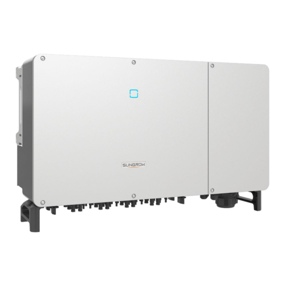
Page 11: Appearance
Designated area for DC switches, AC terminals, DC terminals, and communication terminals. Wiring area For details, refer to section 5.1 Terminal Description 2.2.3 Dimensions and Weight Depth Width Height Fig. 2-4 Dimensions of the Inverter Type Dimensions (Width*Height*Depth) Weight 1051mm * 660mm * 363mm 95kg SG250HX (41.4”x 26” x 14.3”) (209.4lb) -
Page 12: Led Indicator Panel
Both the AC and DC sides of the inverter are powered down. 2.2.5 DC Switch The DC switch is used to disconnect the DC current safely whenever necessary. Fig. 2-5 Location of DC Switches at Bottom View of the SG250HX... -
Page 13: Circuit Diagram
PV power plant in real time and realizes remote data collection and remote O&M functions. It is recommended to use the communication module produced by Sungrow, such as Eye, WiFi, or E-Net. A third-party communication device may cause communication failure or even unpredictable damage. - Page 14 User Manual 2 Product Introduction PID function After the PID function is enabled, the voltage to ground of all PV panels is greater than 0, i.e., the PV panel-to-ground voltage is a positive value. Transformer Grid PV array Inverter Rise the to-ground electromotive force at the negative pole of the PV array Before enabling the PID recovery function, make sure the to-ground voltage polarity of the PV panels meets the requirement.
-
Page 15: Unpacking And Storage
3.2 Identifying the Inverter The nameplate can be found on both the inverter and the packing case. It provides information on type of inverter, important specifications, marks of certification institutions, and serial number which are available and identified by SUNGROW. 光伏并网逆变器... -
Page 16: Scope Of Delivery
User Manual 3 Unpacking and Storage Company name, website and country of manufacture Tab. 3-1 Description of Icons on the Nameplate Icon Description Do not dispose of the inverter together with household waste Refer to the corresponding instructions TÜV mark of conformity CGC-SOLAR mark of conformity CE mark of conformity 3.3 Scope of Delivery... -
Page 17: Inverter Storage
User Manual 3 Unpacking and Storage 3.4 Inverter Storage If the installation of the inverter is not to take place immediately after receipt, the unit must be properly stored under the guidelines and conditions as follows: Use the original packing case with the desiccant inside for storing the inverter. ... -
Page 18: Mechanical Mounting
4 Mechanical Mounting 4.1 Safety During Mounting Make sure there are no live electrical connections before installation. To avoid electric shock or other injuries, ensure there are no electric or plumbing installations before drilling holes. Risk of injury due to improper handling ... -
Page 19: Installation Environment Requirements
User Manual 4 Mechanical Mounting 4.2.1 Installation Environment Requirements The installation environment is free of inflammable materials. The inverter should be installed in a place inaccessible to the children. The ambient temperature and relative humidity must meet the below requirements: Max. -
Page 20: Installation Clearance Requirements
User Manual 4 Mechanical Mounting 4.2.4 Installation Clearance Requirements Reserve enough clearance around the inverter to ensure sufficient space for heat dissipation. Please note that the fans are maintained on the left side of the inverter, and a larger clearance space is required: ≥600mm/23.6"... -
Page 21: Installation Tools
User Manual 4 Mechanical Mounting 4.3 Installation Tools Prepare the following tools before installation, which are not limited to other auxiliary tools: Type Tool Packaging tape Marker Measuring tape Level Utility knife Multimeter Protective clothing Wrist strap 880.0 General tools Protective gloves Dust mask Earplugs... -
Page 22: Moving The Inverter
User Manual 4 Mechanical Mounting 4.4 Moving the Inverter Move the inverter to the specified position before installation. The inverter can be moved manually or via a hoist. 4.4.1 Manual Transport Release the sealing screws on the mounting ears with a flat-head screwdriver and store them properly. Anchor the four supplied Step 1 screw-in handles to the mounting ears and base of the inverter. -
Page 23: Hoisting Transport
User Manual 4 Mechanical Mounting 4.4.2 Hoisting Transport Release the sealing screws on the mounting ears with a flat-head screwdriver and store them properly. Step 1 Step 2 Anchor two M12 thread lifting rings to the mounting ears of the inverter: Lead the sling through the two lifting rings and fasten the tie-down strap. -
Page 24: Pv Bracket-Mounted Installation
User Manual 4 Mechanical Mounting 4.5 PV Bracket-Mounted Installation 4.5.1 Preparation before Mounting Tools Item Specification Phillips screwdriver/ electric screwdriver M4, M6 Marker Level Drill bit: φ12 Hammer drill Socket wrench Including 16mm socket Wrench Opening: 16mm Component parts Item Specification Source Delivery scope... - Page 25 User Manual 4 Mechanical Mounting Secure the mounting-bracket with bolts. Step 4 16mm 35N.m Tab. 4-1 Fastening sequence Item Component Description Mounting-bracket Full threaded bolt M10 x 45 Metal bracket Flat washer Spring washer Hex nuts Remove the inverter from the packing case. Step 5 Hoist the inverter to the installation position as referenced in00of this document.
-
Page 26: Wall-Mounted Installation
User Manual 4 Mechanical Mounting Step 8 Fix the inverter with two M6×65 screws. 4.5N.m 4.6 Wall-Mounted Installation 4.6.1 Preparation before Mounting Tools Item Specification Phillips screwdriver/ electric screwdriver M4, M6 Marker Level Drill bit (Select according to expansion bolt Hammer drill specifications) Socket wrench... - Page 27 User Manual 4 Mechanical Mounting Level the assembled mounting-bracket by using the level, and mark the positions for drilling holes on the installation site Step 2 Insert the expansion bolts into the holes and secure them with a rubber hammer. Fasten the nut with a wrench to expand the bolt. Step 3 Remove the nut, spring washer, and flat washer, and store them properly.
- Page 28 User Manual 4 Mechanical Mounting Hang the inverter to the mounting-bracket and that the mounting ears perfectly engage with the mounting-bracket. Step 7 Fix the inverter with two M6×65 screws. Step 8 4.5N.m...
-
Page 29: Electrical Connection
5 Electrical Connection 5.1 Terminal Description Wiring terminals are at the bottom of the inverter, as shown in the figure below. Fig. 5-1 Wiring terminals *Image shown here is for reference only. The actual product you receive may differ. Item Terminal Print Note... -
Page 30: Safety Instructions
User Manual 5 Electrical Connection 5.2 Safety Instructions High voltage may be present inside the inverter! The PV string will generate lethal high voltage when exposed to sunlight. Do not connect AC&DC circuit breakers before finishing electrical connections. ... - Page 31 *A copper to aluminum adapter terminal is required when an aluminum cable is used. For details, refer to 5.5.3 Aluminum Cable Requirements. **In the case of four single-core cables, a spare AC sealing plate accessory is required. To purchase the AC sealing plate accessory, contact SUNGROW.
-
Page 32: Additional Grounding Connection
User Manual 5 Electrical Connection Tab. 5-2 PE wire requirements PE Wire Conductor Cross-section (mm Note only when materials of the phase wires and PE wire are the same. If otherwise, ensure that the cross-sectional area of the PE wire (S: Phase wire cross-section S) produces a conductance equivalent to that of the wire specified in the table. -
Page 33: Opening The Wiring Compartment
User Manual 5 Electrical Connection Secure the cable to the inverter chassis with a screwdriver. There are two grounding terminals. Use at least one of them to ground the inverter. 5.5 Opening the Wiring Compartment Release two screws on the front cover of the wiring compartment with supplied Allen wrench. ... -
Page 34: Ac Side Requirements
Requirements for Multi-Inverter Parallel Connection If multiple inverters are connected in parallel to the grid, ensure that the total number of parallel inverters does not exceed 28. Otherwise, please contact SUNGROW for technical scheme. MV Transformer The MV transformer coupled with the inverter should meet the following requirements: ... -
Page 35: Requirements For Ot/Dt Terminal
The apparent power of the inverter should never exceed the power of the transformer. The maximum AC current of all inverters connected in parallel must be considered. If more than 25 inverters are connected to the grid, contact SUNGROW. ... -
Page 36: Wiring Procedure
User Manual 5 Electrical Connection Fig. 5-3 Aluminum cable terminal connection sequence Direct contact between the copper bar and the aluminum cable will cause electrochemical corrosion and impair the reliability of electrical connection. 5.5.4 Wiring Procedure Open the wiring compartment. For details, refer to 5.5 Opening the Wiring Compartment ... - Page 37 User Manual 5 Electrical Connection If wiring of tracking system power cable is required, refer to 5.7 Wiring of Tracking System Power Cable (Optional). Otherwise, skip performing this step. Crimp the OT/DT terminals. Secure the wires to corresponding terminals.
- Page 38 User Manual 5 Electrical Connection 20~30 N.m Phase cable 7~9 N.m PE cable Note the terminal positions of PE wire and N wire. If a phase wire is connected to the PE terminal or N terminal, unrecoverable damage may be caused to the inverter. ...
-
Page 39: Pv String Connection
User Manual 5 Electrical Connection If the PE cable is an independent single-core cable, it is inserted into the cabinet through the standby grounding terminal. 5.6 PV String Connection Electric shock! The PV array will generate lethal high voltage once exposed to sunlight. Make sure the PV array is well insulated to ground before connecting it to the inverter. -
Page 40: Connection Procedure
User Manual 5 Electrical Connection To make the best use of PV input power, PV string structure of the same input should be the same in PV module type, PV module number, angle of tilt, and orientation. Open circuit voltage limit Max. -
Page 41: Installing The Pv Connectors
User Manual 5 Electrical Connection Strip insulation layers of all DC cables by about 7mm. Assemble the cable ends with the crimping pliers. Lead the cable through cable gland and insert into the insulator until it snaps into place. Gently pull the cable backward to ensure firm connection. - Page 42 User Manual 5 Electrical Connection Check the cable connection of the PV string for polarity correctness and ensure that the open circuit voltage in any case does not exceed the inverter input limit of 1,500V. Insert the PV connectors to the corresponding terminals until there is an audible click. Check the positive and negative polarity of the PV strings, and insert the PV connector to the corresponding terminal only after ensuring polarity correctness.
-
Page 43: Wiring Of Tracking System Power Cable (Optional)
User Manual 5 Electrical Connection 5.7 Wiring of Tracking System Power Cable (Optional) Lead the AC cable into the wiring compartment according to Step 1 to Step 4 described in 5.5.4 Wiring Procedure. Loosen the swivel nut of the communication terminal and select an appropriate seal according to cable outer diameter. Lead the cable through the swivel nut and seal successively. - Page 44 User Manual 5 Electrical Connection Crimp tracking system power together with two phase s in the AC cable. Other AC s are crimped independently. wires wire wire Secure the wires to corresponding terminals.
-
Page 45: Rs485 Communication
User Manual 5 Electrical Connection Gently pull the cable backwards to ensure firm connection and fasten the swivel nut clockwise. There are four communication terminals COM1, COM2, COM3 and COM4 on the bottom of the inverter. Please choose according to the actual situation. ... -
Page 46: Rs-485 Communication System
User Manual 5 Electrical Connection The inverter is equipped with two groups of RS485 communication interfaces for external communication connection. Both groups of interfaces can be connected to the data collector (Logger), to achieve data exchange with PC or other monitoring devices. When multiple inverters are connected in the RS485 daisy chain, a 120Ω... -
Page 47: Wiring Procedure
User Manual 5 Electrical Connection When more than 15 inverters are connected on the same daisy chain, the inverters on two ends of the chain should be equipped with terminating resistors of 120Ω to ensure communication quality by configuring the dip switch (SW1), and the shielding layer of the communication cable should be single-point grounded. - Page 48 User Manual 5 Electrical Connection Loosen the swivel nut of the communication terminal and select an appropriate seal according to cable outer diameter. Lead the cable through the swivel nut and seal successively. Outer Diameter D (mm) Seal 4.5mm~6mm 6mm~12 mm 13 mm ~18 mm ...
-
Page 49: Dry Contact Connection
User Manual 5 Electrical Connection Gently pull the cable backwards to ensure firm connection and fasten the swivel nut clockwise. 5.9 Dry Contact Connection Dry contact cables require a cross-sectional area of 1 mm to 1.5 mm The connection procedure of the dry contact is the same as that of the RS485 terminal block. 5.9.1 Dry Contact Function The communication circuit board is provided with DO terminal (fault output dry contact) and DI terminal (emergency stop dry contact), as shown in the figure below. - Page 50 User Manual 5 Electrical Connection Fig. 5-6 Normal open contact Fig. 5-7 Normal close contact Cross-section of the cable connected to the dry contact ranges between 28AWG and 16AWG. Devices connected to the relay should comply with related requirements: AC-Side Requirements DC-Side Requirements Max.
-
Page 51: Wiring Procedure
User Manual 5 Electrical Connection The dry contacts only support passive switch signal input. The following figure shows the typical application of local stop dry contact. Fig. 5-8 Local stop contact Ensure that the impedance at the input node is less than 600Ω. 5.9.2 Wiring Procedure Refer to the wiring of terminal block described in chapter 5.8.3 Wiring Procedure. -
Page 52: Communication Module Connection (Optional)
5.11 Communication Module Connection (optional) Connect the communication module produced by Sungrow, such as Eye series, Wi-Fi, or E-Net to the communication accessory port. After successful connection, information such as power generation and running state of the inverter can be viewed via the APP on the phone. -
Page 53: Commissioning
6 Commissioning 6.1 Inspection before Commissioning Check the following items before starting the inverter: The inverter DC switch and external circuit breaker are disconnected. The inverter should be accessible for operation, maintenance, and service. Ensure nothing is left on the top of the inverter or battery pack. ... -
Page 54: Isolarcloud App
iSolarCloud APP 7.1 Introduction The iSolarCloud APP can establish communication connection to the inverter via the Bluetooth communication protocol, thereby achieving local control of the inverter. Users can use the APP to view basic information, alarms, events, set parameters, download logs and etc. -
Page 55: Menu
User Manual 7 iSolar Cloud App 7.3 Menu Fig. 7-1 Menu Tree 7.4 Login 7.4.1 Requirements The following items are required to establish connection with the inverter: The AC and DC sides or the AC side of the inverter is powered-on. The mobile phone is within 5m away from the inverter and there are no obstructions in between. - Page 56 Username is “user” , the initial Login password is "pw1111" which should be changed for the security consideration. To set inverter parameters related to grid protection and grid support, contact SUNGROW to obtain the advanced account and corresponding password. Step 5 Step 4 If the inverter is not initialized, you will enter the “Initialize protection parameter”...
-
Page 57: Home Page
User Manual 7 iSolar Cloud App Reset the protection parameters if the country setting is incorrect. Otherwise, fault may occur. Step 6 When inverter is initialized, the APP automatically turns to its home page. Step 7 Step 5 7.5 Home Page Screen Fig. - Page 58 User Manual 7 iSolar Cloud App Designation Description Navigation bar Including "Home", "Run-info", "His-record", and "More" Tab. 7-2 Description of inverter state State Description After being energized, inverter tracks the PV arrays’ maximum power point (MPP) and converts the DC power into AC power.
-
Page 59: Running Information
User Manual 7 iSolar Cloud App 7.6 Running Information Tap " " on the navigation bar to enter the running information screen, as shown in the following figure. Fig. 7-6 Running Information The run info includes the input, output, string, grid voltage, grid current, environment, and other information. Tab. -
Page 60: History Record
User Manual 7 iSolar Cloud App 7.7 History Record Tap " " on the navigation bar to enter the history record screen, as shown in the following figure. Fig. 7-7 History record On "history record" screen, users can check the alarm records, power yield records and event records. 7.7.1 Fault Alarm Records Tap "... - Page 61 User Manual 7 iSolar Cloud App Fig. 7-9 Detailed fault alarm info...
-
Page 62: Power Yields Records
User Manual 7 iSolar Cloud App 7.7.2 Power Yields Records User can view various energy records: power curve, daily energy histogram, monthly energy histogram, and annual energy histogram. Tab. 7-6 Explanation of power yields records Parameter Description Show the power output from 5 am to 11 pm in a single day. Each point in the curve is the Power curve percentage of nominal power. -
Page 63: More
User Manual 7 iSolar Cloud App 7.8 More Tap " " on the navigation bar to enter the "More" screen, as shown in the following figure. Fig. 7-11 More 7.8.1 Parameter Setting Tap " " to enter the parameter setting screen, as shown in the following figure. Fig. -
Page 64: Password Changing
User Manual 7 iSolar Cloud App 7.8.2 Password Changing Tap " " to enter the modify password screen, as shown in the following figure. Fig. 7-13 Change password The new password should consist of 6 characters, a combination of letters and digits. -
Page 65: System Decommissioning
8 System Decommissioning 8.1 Disconnecting the Inverter For maintenance or other service work, the inverter must be switched off. Proceed as follows to disconnect the inverter from the AC and DC power sources. High voltages sources shall be disconnected to avoid personal injury and equipment damage. -
Page 66: Disposal Of The Inverter
User Manual 8 System Decommissioning 8.3 Disposal of the Inverter Users take the responsibility for the disposal of the inverter. Some parts and devices of the inverter, such as the capacitors, may cause environment pollution. Do not dispose of the product together with household waste but in accordance with the disposal regulations for electronic waste applicable at the installation site. -
Page 67: Troubleshooting
LCD. 3. Check whether the cross-sectional area of the AC cable meets the requirement. 4. If the fault is not caused by the external condition and still exists, contact Sungrow Service. Inverter will reconnect to the grid after the grid returns to normal. If the fault continues to... - Page 68 Excessive Leakage Current 2. If the environment is normal, check whether the AC and DC cables are well insulated. 3. If the fault is not caused by the external condition and still exists, contact Sungrow Service. Inverter will reconnect to the grid after the grid returns to normal. If the fault continues to...
- Page 69 4. Perform a Megger test on the DC cables. 5. If the fault is not caused by the external condition and still exists, contact Sungrow Service. Wait for the inverter to return to normal.
- Page 70 PV-X Abnormal 2. Check if the X- DC fuse is damaged. If so, replace the fuse. 3. If the fault is not caused by the external condition and still exists, contact Sungrow Service. *The code 220 to code 227 are corresponding to PV 5 to PV 12 respectively.
-
Page 71: Maintenance
Unauthorized alterations will void guarantee and warranty claims and in most cases terminate the operating license. SUNGROW shall not be held liable for any damage caused by such changes. Any malfunction that may impair the inverter safety operation must be repaired immediately before the inverter is restarted. - Page 72 User Manual 9 Troubleshooting and Maintenance 9.2.2 Maintenance Instruction Fan Maintenance Fans inside the inverter are used for heat dissipation. If the fans do not operate normally, the inverter may not be cooled down and inverter efficiency may compromise. Therefore, it is necessary to clean the dirty fans and replace the broken fans in time. Stop the inverter and disconnect it from all power supplies before maintenance....
- Page 73 User Manual 9 Troubleshooting and Maintenance In order to maintain good ventilation, please check to make sure the air inlet and outlet are not blocked. Clean the air inlet and outlet with soft brush or vacuum cleaner if necessary.
-
Page 74: Appendix
10 Appendix 10.1 Technical Data Parameters SG250HX Input (DC) Max. PV input voltage 1500 V Min.PV input voltage/Startup input voltage 600 V / 600 V Nominal input voltage 1080 V MPP voltage range 600 V – 1500 V MPP voltage range for nominal power 860 V –... - Page 75 Cooling method Smart forced air cooling 4000 m (> 3000 m derating) 13123 ft (> 9843 ft Max. operating altitude derating) Parameters SG250HX Display LED, Bluetooth + APP Communication RS485 / Optional: PLC DC connection type MC4-EVO2 (Max. 6 mm² / 10AWG ) OT terminal (Max.
-
Page 76: Quality Assurance
10 Appendix 10.2 Quality Assurance When product faults occur during the warranty period, SUNGROW will provide free service or replace the product with a new one. Evidence During the warranty period, the customer shall provide the product purchase invoice and date. In addition, the trademark on the product shall be undamaged and legible. -
Page 77: Contact Information
We need the following information to provide you the best assistance: Type of the inverter Serial number of the inverter Fault code/name Brief description of the problem China (HQ) Australia SUNGROW POWER SUPPLY Co., Ltd SUNGROW Australia Group Pty. Ltd. Hefei +86 551 65327834 +61 2 9922 1522 service@sungrowpower.com service@sungrowpower.com.au... - Page 78 10 Appendix 10.4 Legal Statement All Rights Reserved No part of this document can be reproduced in any form or by any means without the prior written permission of Sungrow Power Supply Co., Ltd. Trademarks and other Sungrow trademarks used in this manual are owned by Sungrow Power Supply Co., Ltd.
Need help?
Do you have a question about the SG250HX and is the answer not in the manual?
Questions and answers