Toro Reelmaster 3100-D Operator's Manual
Traction unit
Hide thumbs
Also See for Reelmaster 3100-D:
- Service manual (385 pages) ,
- Operator's manual (72 pages) ,
- Installation instructions manual (16 pages)

Related Manuals for Toro Reelmaster 3100-D


Summary of Contents for Toro Reelmaster 3100-D
- Page 1 Operator’s Manual Reelmaster® 3100-D Traction Unit Model—Serial Range 03170—415300000 and Up 03171—415400000 and Up *3466-297* A 3466-297A Original Instructions (EN)
-
Page 2: Table Of Contents
After Operation Safety........................2–4 Maintenance Safety ......................... 2–5 Engine Safety ..........................2–5 Electrical System Safety ......................2–5 © 2023—The Toro ® Company Contact us at www.Toro.com 8111 Lyndale Ave So Printed in the USA Bloomington, MN 55044 All rights reserved... -
Page 3: Disclaimers And Regulatory Information
Cooling System Safety........................ 2–5 Hydraulic System Safety......................2–6 Blade Safety ..........................2–6 Storage Safety ..........................2–6 Safety and Instructional Decals ....................2–7 Chapter 3: Setup........................... 3–1 1 Installing the Wheels ........................3–1 2 Installing the Steering Wheel ..................... 3–2 3 Charging and Connecting the Battery..................3–3 4 Checking the Slope Indicator ..................... - Page 4 Fuel Gauge ............................ 4–6 Tilt-Steering Lever ........................4–7 Seat Adjustment Lever........................ 4–7 Specifications ............................ 4–8 Attachments/Accessories....................... 4–8 Chapter 5: Operation ........................... 5–1 Before Operation ..........................5–1 Performing Daily Maintenance ....................5–1 Fuel ..............................5–1 Checking the Interlock Switches....................5–3 During Operation ..........................5–4 Starting the Engine........................
- Page 5 Storing the Machine ......................... 7–1 Storing the Battery..........................7–1 Chapter 8: Troubleshooting ....................... 8–1 Using the Standard Control Module (SCM)................8–1 Troubleshooting the Standard Control Module (SCM) ............8–2 The Toro Warranty California Proposition 65 Warning Information 3466-297 A Disclaimers and Regulatory Information:...
-
Page 6: Chapter 1: Introduction
Whenever you need service, genuine Toro parts, or additional information, contact an Authorized Service Dealer or Toro Customer Service and have the model and serial numbers of your product ready. These numbers are located on the serial plate on your product . -
Page 7: Manual Conventions
Manual Conventions This manual identifies potential hazards and has safety messages identified by the safety- alert symbol, which signals a hazard that may cause serious injury or death if you do not follow the recommended precautions. G405934 This manual uses 2 words to highlight information. Important calls attention to special mechanical information and Note emphasizes general information worthy of special attention. -
Page 8: Chapter 2: Safety
Chapter 2 Safety General Safety • This product is capable of amputating hands and feet and of throwing objects. • Read and understand the contents of this Operator’s Manual before starting the engine. • Use your full attention while operating the machine. Do not engage in any activity that causes distractions;... -
Page 9: Fuel Safety
• Before mowing, always inspect the machine to ensure that the cutting units are in good working condition. • Inspect the area where you will use the machine and remove all objects that the machine could throw. • This product generates an electromagnetic field. If you wear an implantable electronic medical device, consult your health care professional before using this product. -
Page 10: Rollover Protection System (Rops) Safety
• Operate the engine only in well-ventilated areas. Exhaust gasses contain carbon monoxide, which is lethal if inhaled. • Do not leave a running machine unattended. • Before you leave the operator’s position, do the following: – Park the machine on a level surface. –... -
Page 11: After Operation Safety
Slope Safety (continued) – Remove or mark obstructions such as ditches, holes, ruts, bumps, rocks, or other hidden hazards. Tall grass can hide obstructions. Uneven terrain could overturn the machine. – Be aware that operating the machine on wet grass, across slopes, or downhill may cause the machine to lose traction. -
Page 12: Maintenance Safety
• Keep all parts of the machine in good working condition and all hardware tightened. • Replace all worn or damaged decals. • To ensure safe, optimal performance of the machine, use only genuine Toro replacement parts. Replacement parts made by other manufacturers could be dangerous, and such use could void the product warranty. -
Page 13: Hydraulic System Safety
Cooling System Safety (continued) • Discharge of hot, pressurized coolant or touching a hot radiator and surrounding parts can cause severe burns. – Always allow the engine to cool at least 15 minutes before removing the radiator cap. – Use a rag when opening the radiator cap, and open the cap slowly to allow steam to escape. -
Page 14: Safety And Instructional Decals
Safety and Instructional Decals Safety decals and instructions are easily visible to the operator and are located near any area of potential danger. Replace any decal that is damaged or missing. Battery Symbols Some or all of these symbols are on your battery. s_batterysymbols2 Wear eye protection;... - Page 15 Decal Part: 99-3444 Transport speed—fast Mowing speed—slow s_decal99-3444 Decal Part: 106-9290 Model 03170 Neutral Parking brake—Off In seat High temperature shutdown Reels—active High temperature warning Inputs Outputs Power Engine—Start Engine—Run Engine—Start s_decal106-9290 Decal Part: 117-3270 Warning—do not touch the hot surface.
- Page 16 Decal Part: 121-3598 CE Machines Tipping hazard—do not drive across slopes greater than 17°. s_decal121-3598 Note: This machine complies with the industry standard stability test in the static lateral and longitudinal tests with the maximum recommended slope indicated on the decal. Review the instructions for operating the machine on slopes in the Operator’s Manual as well as the conditions in which you would operate the machine to determine whether you can operate the machine in the conditions on that day and at that site.
- Page 17 Decal Part: 121-3623 s_decal121-3623 Warning—read the Operator's Manual; do not Warning—do not park on slopes; engage the operate the machine unless you have received parking brake, stop the cutting units, lower the training. attachments, shut off the engine, and remove the key from the ignition before leaving the machine.
- Page 18 Decal Part: 125-6688 Explosion hazard—Read the Operator’s Manual; Do not use starting fluid. s_decal125-6688 Decal Part: 133-8062 s_decal133-8062 Safety: Safety and Instructional Decals Page 2–11 3466-297 A...
- Page 19 Decal Part: 136-3678 Model 03170 PTO—Disengage PTO—Engage Lower the cutting units. Raise the cutting units. Lock Engine—Shut off Engine—Run Engine—Start Lights Fast Slow s_decal136-3678 Decal Part: 136-3679 Model 03171 PTO—Disengage PTO—Engage Lower the cutting units. Raise the cutting units. Shift the cutting units to the right. Shift the cutting units to the left.
- Page 20 Decal Part: 136-3702 Warning—Read the Operator’s Manual; wear a seatbelt; do not remove the roll bar. Warning—Do not modify the roll bar. s_decal136-3702 Decal Part: 136-3716 s_decal136-3716 Check every 8 Capacity Reel speed Engine coolant hours. Fluid interval Tire pressure Fuses Read the (hours)
- Page 21 Decal Part: 147-6069 Reel speed Reel height of cut 8-blade reel adjustment 11-blade reel adjustment Slow Fast s_decal147-6069 3466-297A Page 2–14 Safety: Safety and Instructional Decals...
-
Page 22: Chapter 3: Setup
Chapter 3 Setup Installing the Wheels Parts Required Front wheel assembly Rear wheel assembly 1. Mount a wheel assembly onto the wheel hub with the valve stem aligned outward. Note: The rear wheel is narrower than the front wheels. 2. Secure the wheel to the hub with the lug nuts, and torque the nuts in a crossing pattern to 61 to 88 N∙m (45 to 65 ft-lb). -
Page 23: Installing The Steering Wheel
Installing the Steering Wheel Parts Required Steering wheel Steering-wheel cap Large washer Jam nut Screw 1. Install the steering wheel as shown. 2. Torque the nut to 27 to 35 N∙m (20 to 26 ft-lb). G402549 3466-297A Page 3–2 Setup: Installing the Steering Wheel... -
Page 24: Charging And Connecting The Battery
Charging and Connecting the Battery DANGER Battery electrolyte contains sulfuric acid, which is lethal if consumed and causes severe burns. • Do not drink electrolyte and avoid contact with skin, eyes, or clothing. • Wear safety glasses and rubber gloves. •... -
Page 25: Checking The Slope Indicator
7. Coat both battery connections with Grafo 112X skin-over grease (Toro Part No. 505-47) or light grease to prevent corrosion. 8. Slide the rubber boot over the positive terminal to prevent a possible short from occurring. -
Page 26: Installing The Roll Bar
4. Check the slope indicator mounted on the steering tube of the machine. Note: The slope indicator should read 0° when viewed from the operator’s position. 5. If the slope indicator does not read 0°, loosen the hardware securing the angle indicator to the mounting bracket, adjust the indicator to G402560 attain a 0°... -
Page 27: Installing The Front Lift Arms
Installing the Front Lift Arms Parts Required Lift arm kit (optional kit—order separately) Preparing to Install the Lift Arms 1. Insert a pivot rod into each lift arm align the mounting holes. 2. Secure the pivot rods to the lift arms with 2 bolts (5/16 x 7/8 inch). -
Page 28: Assembling The Lift Cylinder To The Left Lift Arm
Assembling the Lift Cylinder to the Left Lift Arm 1. Assembly the lift cylinder to the left lift arm as shown. 2. Apply No. 2 lithium grease to the grease fittings of the lift arm and the hydraulic cylinder. G402568 Assembling the Lift Cylinder to the Right Lift Arm 1. -
Page 29: Installing The Carrier Frames To The Cutting Units
Assembling the Lift Cylinder to the Right Lift Arm (continued) IMPORTANT Some hydraulic fluid is forced out at the hose fittings when you move the lift-cylinder rod. 5. Assemble the rod to the flanges with the mounting pin , 2 spacers , and 2 snap rings 6. -
Page 30: Assembling The Cutting Unit And Rear Carrier Frame
Assembling the Carrier Frames for the Front Cutting Units (continued) 1. Align the holes in the plates of the front-carrier frame with the holes in the cutting unit mounting plates. Note: If you are starting assembly at the back of the cutting unit, use the middle hole of the plate. -
Page 31: Assembling The Cutting Unit And Rear Carrier Frame
Assembling the Carrier Frames for the Front Cutting Units (continued) 1. Align the holes in the plates of the front-carrier frame with the holes in the cutting unit mounting plates. Note: If you are starting assembly at the back of the cutting unit, use the middle holes of each plate. -
Page 32: Installing The Cutting Units
Installing the Cutting Units 1. Slide a thrust washer onto each lift-arm pivot rod. 2. Slide the cutting-unit-carrier frame onto the pivot rod and secure it with a lynch pin Note: On rear cutting units, position the thrust washer between the rear of the carrier frame and the lynch pin. -
Page 33: Installing The Cutting Unit Drive Motors
Installing the Cutting Unit Drive Motors 1. Position the cutting units in front of the lift-arm- pivot rods. 2. Remove the weight , O-ring , and 2 mounting bolts from the end of the right cutting unit. 3. Remove the plug from the bearing housing and install the weight and O-ring. -
Page 34: Adjusting The Lift-Arm Clearance
Checking Lift Arm and Rear Cutting Unit Clearance (continued) IMPORTANT A lack of clearance at the front plate bracket could damage the lift arms. 3. At the rear cutting unit, measure the clearance between the wear strap on the top of the rear cutting unit wear bar and the bumper stop Note:... -
Page 35: Adjusting The Lift-Arm Stop Bolts
Adjusting the Lift-Arm Clearance (continued) 2. Loosen the jam nut on the lift-cylinder rod 3. Remove the pin from the rod end and rotate the clevis jam nut. 4. Install the pin and check the clearance. 5. Repeat steps through if necessary. -
Page 36: Preparing The Machine
Adjusting the Rear Cutting Unit Clearance (continued) 2. Grasp the cylinder rod close to the jam nut with a pliers and rag, and rotate the rod. Note: Shortening the rod reduces wear strap and bumper stop clearance. 3. Start the engine, raise the cutting units, shut off the engine, remove the key, and wait for all G402589 moving parts to stop. -
Page 37: Installing The Hood Latch
Installing the Hood Latch CE Machines Parts Required Hood-latch bracket Rivet Washer Screw (1/4 x 2 inches) Locknut (1/4 inch) 1. Unhook the hood latch from the hood-latch bracket. 2. Remove the 2 rivets and the hood-latch bracket from the hood. G402590 3. -
Page 38: Installing The Exhaust Guard
7. Screw the bolt into the other arm of hood- latch bracket to lock the latch in position. Note: Tighten the nut and bolt until the bolt no longer moves forward and backward in the hood-latch bracket. G402593 Installing the Exhaust Guard CE Machines Parts Required Exhaust guard... -
Page 39: Applying The Year Of Production Decal And Ce Decal
Applying the Year of Production Decal and CE Decal 1. Wipe the left frame, near the model/serial plate , with alcohol and allow the frame to dry. 2. Remove the backing and apply the Year of Production decal to the frame near the serial plate. - Page 40 2. Locate the frame bracket above the center cutting unit. 3. Press down on the front roller of the center cutting unit and align the holes on the tipper bracket with the frame bracket holes to attain the same roller contact when the tipper G402598 bracket is installed.
-
Page 41: Chapter 4: Product Overview
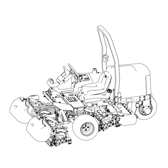
Chapter 4 Product Overview Engine hood Operator's seat Control arm Steering wheel Seat-adjustment lever Front cutting units Rear cutting unit G403727 Controls G450123 Cutting-unit shift lever Glow-plug indicator light Tilt-steering lever Throttle Slope indicator Cutting-unit drive switch Alternator light Forward traction pedal Oil-pressure light Key switch Engine coolant temperature... -
Page 42: Key Switch
Key Switch Run/preheat the engine Note: When the key is in the R position, the glow plug REHEAT energizes and the indicator light illuminates for approximately 7 seconds. Start G444247 Traction Pedals Move forward—press the forward traction pedal. Move backward (or to assist in stopping when moving forward)—press the reverse traction pedal. -
Page 43: Cutting Unit Shift Lever
Cutting Unit Shift Lever Raise/Lower Lower Note: The cutting units do not lower unless the engine is running. You do not need to hold the lever in the forward position while the cutting units are lowered. Raise Note: The reels do not run while the cutting units are raised. -
Page 44: Indicator Slot
Indicator Slot The slot in the operator platform indicates when the cutting units are in the center position. Cutting-Unit Drive Switch Disengage Engage G453441 Throttle Increase engine speed Decrease engine speed G465025 Lift Lever Lock Unlock Lock (prevents cutting units from dropping) G465028 Parking Brake... -
Page 45: Oil Pressure Warning Light
Parking Brake (continued) Engaged Disengaged G465039 Note: The engine shuts off if you press the traction pedal with the parking brake engaged. Oil Pressure Warning Light The oil pressure warning light glows if the engine oil pressure drops below a safe level. Engine Coolant Temperature Warning Light The temperature warning light illuminates if the engine coolant temperature is high. -
Page 46: Fuel Gauge
Mower Manifold (continued) G465040 Reel speed control Backlap control Reel Speed Knob Use the reel speed knob of the mower manifold to adjust the clip rate (reel speed) of the cutting units. Turn the reel speed knob counterclockwise to increase the reel speed; turn the knob clockwise to slow the reel speed. -
Page 47: Tilt-Steering Lever
Tilt-Steering Lever Unlock the tilt-steering lever, tilt the steering wheel to the desired position, and lock the lever to secure the position. Unlock Lock G444513 Seat Adjustment Lever Move the lever to the unlock position, adjust the seat to the desired position, and lock the lever to secure the seat position. -
Page 48: Specifications
0 to 6 km/h (0 to 4 mph) *With cutting units and fluids Attachments/Accessories A selection of Toro approved attachments and accessories is available for use with the machine to enhance and expand its capabilities. Contact your Authorized Service Dealer or authorized Toro distributor or go to www.Toro.com... -
Page 49: Chapter 5: Operation
Chapter 5 Operation Before Operation Performing Daily Maintenance Before starting the machine each day, perform the Each Use/Daily procedures listed in the Maintenance Schedule. Fuel Fuel Specifications IMPORTANT Never use kerosene or gasoline instead of diesel fuel. Petroleum Diesel Type Use summer grade diesel fuel (No. - Page 50 Monitor seals, hoses, gaskets in contact with fuel as they may degrade over time. Fuel filter plugging may be expected for a time after converting to biodiesel blended. For more information on biodiesel, contact your authorized Toro distributor. Storage Acquire only enough clean, fresh diesel fuel or biodiesel fuel that you will consume within 180 days.
-
Page 51: Checking The Interlock Switches
• Check the operation of the interlock switches daily and replace any damaged switches before operating the machine. IMPORTANT If your machine fails any of the interlock switch checks, contact your authorized Toro distributor. Preparing the Machine 1. Drive the machine slowly to an open area. -
Page 52: During Operation
Checking the Interlock Switches (continued) 5. Rise off the operator’s seat. Note: The engine should shut off if you are out of the operator’s seat and the parking brake is disengaged. Checking the Parking Brake and Traction Pedal Run-Interlock 1. Sit in the operator’s seat and engage the parking brake. 2. -
Page 53: Shutting Off The Engine
Starting the Engine (continued) 3. Move the throttle lever to the 1/2 throttle position. 4. Insert the key into the switch and rotate it to the O position until the glow plug REHEAT indicator light shuts off (approximately 7 seconds); then rotate the key to the S TART position to engage the starter motor. -
Page 54: Side-Shifting The Cutting Units
Cutting Grass with the Machine (continued) 6. Raise the cutting units off the ground using the cutting-unit-shift lever. 7. Once you reach the edge of the mowing area to start mowing, lower the cutting units using the cutting-unit-shift lever. Note: Practice to ensure the cutting units do not lower early or mow an unintended area. -
Page 55: Driving The Machine In Transport Mode
Driving the Machine in Transport Mode 1. Move the cutting-unit-drive switch to the position. ISENGAGE 2. Raise the cutting units to the transport position. 3. Move the mow/transport slide left to the position. RANSPORT G402852 IMPORTANT Be careful when driving between objects so that you do not accidentally damage the machine or the cutting units. -
Page 56: Clip Rate (Reel Speed)
Clip Rate (Reel Speed) To achieve a consistent, high quality-of-cut and a uniform after-cut appearance, it is important that the reel speed be matched to the height-of-cut. IMPORTANT If the reel speed is too slow, you may notice visible clip marks. If the reel speed is too fast, the cut may have a fuzzy appearance. -
Page 57: Adjusting The Reel Speed
Adjusting the Reel Speed 1. Verify the height-of-cut setting on the cutting units. Use the column of the Reel Speed Selection Chart listing either 8-blade or 11- blade reels, and find the height-of-cut listing nearest the actual height-of-cut setting. Look across the chart to find the reel-speed number that corresponds to that height-of-cut. -
Page 58: Operating Tips
Bleeding the Fuel System (continued) 6. Tighten the screw and turn the ignition key to the O position. Note: The engine should start after you follow this procedure. If the engine does not start, you may need to bleed air from the injectors. Operating Tips Mowing Techniques •... -
Page 59: After Operation
After Mowing Wash the machine and grease it. Towing the Machine In case of an emergency, you can tow the machine for a short distance; however, Toro does not recommend this as a standard procedure. IMPORTANT Do not tow the machine faster than 3 to 4 km/h (2 to 3 mph) because it may damage the drive system. -
Page 60: Tie-Down Point Locations
Tie-Down Point Locations G413471 Tie-down loops Hauling the Machine Follow the tips below when hauling the machine. • Use full-width ramps for loading the machine onto a trailer or truck. • Tie the machine down securely. Operation: Tie-Down Point Locations Page 5–12 3466-297 A... -
Page 61: Chapter 6: Maintenance
Determine the left and right sides of the machine from the normal operating position. Note: Download a free copy of the electrical or hydraulic schematic by visiting www.Toro.com searching for your machine from the Manuals link on the home page. IMPORTANT Refer to your engine owner’s manual and cutting unit Operator's Manual for... - Page 62 Maintenance Qty Description Maintenance Procedure Part No. Service Interval Check the hydraulic lines and hoses. PX Extended Life Hydraulic Fluid 133-8086 (5 gallons) Check the hydraulic-fluid level. PX Extended Life Hydraulic Fluid 133-8087 (55 gallons) Check the reel-to-bedknife contact. Check the electrolyte level (if Every 25 hours machine is in storage, check every 30 days).
- Page 63 Maintenance Qty Description Maintenance Procedure Part No. Service Interval have ever filled the reservoir with an alternative fluid). Replace the hydraulic filter Every 1,000 hours you are using the recommended Hydraulic filter 86-3010 hydraulic fluid). PX Extended Life Hydraulic Fluid 133-8086 Change the hydraulic fluid (if you...
-
Page 64: Daily Maintenance Checklist
Daily Maintenance Checklist Maintenance Check Item For the week of: Mon. Tues. Wed. Thurs. Fri. Sat. Sun. Check the safety interlock operation. Check the brake operation. Check the levels of the engine oil and fuel. Check the cooling-system fluid level. Drain the water/fuel separator. -
Page 65: Pre-Maintenance Procedures
Pre-Maintenance Procedures Preparing for Maintenance 1. Park the machine on a level surface, lower the cutting units, and engage the parking brake. 2. Shut off the engine, remove the key, wait for all moving parts to stop, and allow the engine to cool. -
Page 66: Lifting The Back Of The Machine (Using A Jack)
Lifting the Back of the Machine (Using a Jack) 1. Chock the tires. 2. Jack the back of the machine under the rear wheel motor 3. Support the machine with jack stands rated for the weight of the machine under the frame G447817 Removing the Battery Cover Remove the battery cover as shown. -
Page 67: Lubrication
Opening the Hood (continued) 2. Rotate the hood open. G414712 Lubrication Greasing the Bearings and Bushings The machine has grease fittings that must be lubricated regularly. Dusty and dirty operating conditions could cause dirt to get into the bearings and bushings, resulting in accelerated wear. -
Page 68: Grease Fitting Locations
Greasing the Bearings and Bushings (continued) Grease Fitting Locations Grease Specification: No. 2 lithium grease Rear cutting unit pivot G450432 Front cutting unit pivot G450435 Sidewinder cylinder ends (2 fittings; Model 03171 only) G450436 Maintenance: Lubrication Page 6–8 3466-297 A... - Page 69 Greasing the Bearings and Bushings (continued) Steering pivot G450437 Rear lift arm pivot and lift cylinder (2 fittings) G450438 Left front lift arm pivot and lift cylinder (2 fittings) G450439 Right front lift arm pivot and lift cylinder (2 fittings) G450440 3466-297A Page 6–9...
- Page 70 Greasing the Bearings and Bushings (continued) Neutral adjust mechanism G450441 Mow/transport slide G450442 Belt tension pivot G450443 Maintenance: Lubrication Page 6–10 3466-297 A...
- Page 71 Greasing the Bearings and Bushings (continued) Steering cylinder G450444 Note: If desired, install an additional grease fitting in the other end of the steering cylinder. Remove the tire, install the fitting, grease the fitting, remove the fitting, and install the plug. G450445 3466-297A Page 6–11...
-
Page 72: Checking The Sealed Bearings
Use the following engine oil viscosity grade: • Preferred oil: SAE 15W-40 [-17°C (above 0°F)] • Alternate oil: SAE 10W-30 or 5W-30 (all temperatures) Toro Premium Engine Oil is available from your authorized Toro distributor in either 15W-40 or 10W-30 viscosity grades. Crankcase Capacity Approximately 3.8 L (4.0 US qt) with the filter... -
Page 73: Checking The Engine-Oil Level
Checking the Engine-Oil Level Note: Check the oil when the engine is cool. If the engine is warm, wait 10 minutes before checking. If the oil level is below the lower limit mark on the dipstick, add oil gradually until the level reaches the upper limit mark on the dipstick. - Page 74 Changing the Engine Oil and Filter (continued) G414739 4. Change the engine-oil filter. G414740 Note: Do not overtighten the filter. 5. Add oil to the crankcase. Maintenance: Engine Maintenance Page 6–14 3466-297 A...
-
Page 75: Servicing The Air Cleaner
Changing the Engine Oil and Filter (continued) G453108 6. Close and latch the hood. Servicing the Air Cleaner • Check the whole intake system for leaks, damage, or loose hose clamps. Do not use a damaged air filter. • Service the air-cleaner filter at the recommended service interval or earlier if engine performance declines due to extremely dusty, dirty conditions. -
Page 76: Fuel System Maintenance
Servicing the Air Cleaner (continued) G448875 Fuel System Maintenance This Operator’s Manual contains more detailed fuel and fuel system maintenance information than the engine Owner’s Manual, which is a general-purpose reference relating to fuel and fuel maintenance. Ensure that you understand that the fuel system maintenance, fuel storage, and fuel quality require your attention to avoid downtime and extensive engine repairs. -
Page 77: Fuel Storage
IMPORTANT If you do not follow the procedures for fuel filter replacement, fuel system maintenance, and fuel storage, the engine fuel system could fail prematurely. Perform all fuel system maintenance at the specified intervals or whenever the fuel is contaminated or its quality is poor. Fuel Storage Appropriate fuel storage is critical for your engine. -
Page 78: Servicing The Fuel/Water Separator
Servicing the Fuel/Water Separator Draining the Fuel/Water Separator 1. Prepare the machine for maintenance. 2. Drain the water separator as shown. G452998 3. Start the engine, check for leaks, and shut off the engine. Note: Repair all fuel leaks. Maintenance: Fuel System Maintenance Page 6–18 3466-297 A... -
Page 79: Bleeding Air From The Injectors
Servicing the Fuel/Water Separator (continued) Replacing the Fuel/Water Separator Filter 1. Replace the filter as shown. G452996 2. Start the engine, check for leaks, and shut off the engine. Note: Repair all fuel leaks. Bleeding Air from the Injectors Note: Use this procedure only if the fuel system has been purged of air through normal priming procedures and the engine does not start. -
Page 80: Electrical System Maintenance
Bleeding Air from the Injectors (continued) G415052 Fuel injectors 4. Move the throttle to the F position. 5. Turn the key to the S position and watch the fuel flow around the connector. Turn the TART key to the O position when there is a continuous flow. - Page 81 Servicing the Battery (continued) WARNING Incorrectly routing the battery cable could damage the machine and cables, causing sparks. Sparks can cause the battery gasses to explode, which could result in death or serious injury. • Always disconnect the negative (black) battery cable before disconnecting the positive (red) cable.
-
Page 82: Servicing The Fuses
Servicing the Fuses 1. Prepare the machine for maintenance. 2. Lift the cover from the control arm. G416222 Fuse holder Right side of the machine Fuse block Control-arm cover 3. Locate the open fuse in the fuse holder or fuse block. 4. -
Page 83: Torquing The Wheel Nuts
Torquing the Wheel Nuts Torque the wheel nuts in a crossing pattern to 61 to 88 N∙m (45 to 65 ft-lb). WARNING Failing to maintain proper torque of the wheel nuts could result in death or serious injury. Maintain proper torque of the wheel nuts. Adjusting the Traction Drive for Neutral If the machine moves when the traction pedal is in the neutral position, adjust the traction cam. -
Page 84: Cooling System Maintenance
Adjusting the Traction Drive for Neutral (continued) WARNING The engine must be running to make a final adjustment of the traction adjustment cam. Contact with hot or moving parts could result in death or serious injury. Keep your hands, feet, face, and other body parts away from the muffler, other hot parts of the engine, and rotating parts. -
Page 85: Checking The Coolant Level
Coolant Specifications (continued) Extended Life Coolant Standards ATSM International SAE International D3306 and D4985 J1034, J814, and 1941 IMPORTANT Coolant concentration should be a 50/50 mixture of coolant to water. • Preferred: When mixing coolant from a concentrate, mix it with distilled water. •... -
Page 86: Cleaning The Engine Cooling System
Checking the Coolant Level (continued) IMPORTANT Do not overfill the expansion tank. 5. Close and latch the hood. Cleaning the Engine Cooling System 1. Prepare the machine for maintenance. 2. Unlatch and open the hood. 3. Clean the engine area thoroughly of all debris. 4. -
Page 87: Belt Maintenance
Belt Maintenance Servicing the Engine Belts Tensioning the Alternator/Fan Belt 1. Prepare the machine for maintenance. 2. Unlatch and open the hood. 3. Check the alternator/fan belt tension by pressing the belt midway between the alternator and crankshaft pulleys. Note: With 98 N (22 lb) of force, the belt should deflect 11 mm (7/16 inch). -
Page 88: Controls Maintenance
Servicing the Engine Belts (continued) G416950 Pump mount tab Drive belt Hydrostat pulley Belt-tension spring Engine pulley 3. Replace the belt. 4. Push down the end of the belt-tension spring, and inward, and align it into the notch in the pump mount tab. Controls Maintenance Adjusting Mow Ground Speed 1. -
Page 89: Adjusting The Throttle
The reservoir is filled at the factory with high-quality hydraulic fluid. Check the level of the hydraulic fluid before you first start the engine and daily thereafter. Recommended hydraulic fluid: Toro PX Extended Life Hydraulic Fluid; available in 19 L (5 US gallon) pails or 208 L (55 US gallon) drums. -
Page 90: Checking The Hydraulic-Fluid Level
Toro Premium Synthetic Biodegradable Hydraulic Fluid is the only synthetic biodegradable fluid approved by Toro. This fluid is compatible with the elastomers used in Toro hydraulic systems and is suitable for a wide-range of temperature conditions. This fluid is compatible with conventional mineral oils, but for maximum biodegradability and performance, the hydraulic system should be thoroughly flushed of conventional fluid. -
Page 91: Inspecting The Hydraulic Lines And Hoses
Allow the hydraulic fluid to cool before performing any maintenance to the hydraulic system. If the fluid becomes contaminated, contact your authorized Toro distributor because the system must be flushed. Contaminated fluid looks milky or black when compared to clean oil. - Page 92 Changing the Hydraulic Fluid (continued) Hydraulic filter Filter head G417015 3. Install the hydraulic hose when hydraulic fluid stops draining. 4. Fill the tank with the specified hydraulic fluid. IMPORTANT Use only the hydraulic fluids specified. Other fluids could cause system damage. Filler neck (hydraulic-fluid reservoir) Dipstick...
-
Page 93: Changing The Hydraulic Filter
Allow the hydraulic fluid to cool before performing any maintenance to the hydraulic system. Use a genuine Toro replacement filter (Part No. 86-3010). IMPORTANT Use of any other filter may void the warranty on some components. 1. Prepare the machine for maintenance. -
Page 94: Backlapping The Cutting Units
• Never attempt to turn the cutting units by hand or foot while the engine is running. Note: Additional instructions and procedures on backlapping are available in the Toro Reel Mower Basics (with sharpening guidelines), Form 09168SL. Preparing the Machine 1. - Page 95 Backlapping the Cutting Units (continued) Lapping the Reels and Bedknife WARNING Changing the engine speed while backlapping may cause the cutting units to stall, which could result in death or serious injury. • Never change the engine speed while backlapping. •...
-
Page 96: Chassis Maintenance
Backlapping the Cutting Units (continued) IMPORTANT If you do not change backlap lever to the F (mow) position after backlapping, the cutting units will not function properly. G417036 Reel speed control knob Backlap lever 4. Install the console cover to the control console. 5. - Page 97 Washing the Machine (continued) IMPORTANT • Do not use brackish or reclaimed water to clean the machine. • Do not use power-washing equipment to wash the machine. Power-washing equipment may damage the electrical system, loosen important decals, or wash away necessary grease at friction points. Avoid excessive use of water near the control panel, engine, and battery.
-
Page 98: Chapter 7: Storage
A. Remove the battery terminals from the battery posts. B. Clean the battery, terminals, and posts with a wire brush and baking-soda solution. C. Coat the cable terminals and battery posts with Grafo 112X skin-over grease (Toro Part No. 505-47) or petroleum jelly to prevent corrosion. - Page 99 the charge in the battery. To prevent the battery from freezing, ensure that it is fully charged. The specific gravity of a fully charged battery is 1.265 to 1.299. 3466-297A Page 7–2 Storage: Storing the Battery...
-
Page 100: Chapter 8: Troubleshooting
Chapter 8 Troubleshooting Using the Standard Control Module (SCM) The Standard Control Module is a potted electronic device produced in a one-size-fits-all configuration. The module uses solid state and mechanical components to monitor and control standard electrical features required for safe product operation. The module monitors inputs including neutral, parking brake, PTO, start, backlap, and high temperature. -
Page 101: Troubleshooting The Standard Control Module (Scm)
Troubleshooting the Standard Control Module (SCM) 1. Determine the output fault you are trying to resolve (PTO, START, or ETR). 2. Move the key switch to the O position and ensure that the red power LED is illuminated. 3. Move all the input switches to ensure that all LEDs change state. 4. - Page 102 Troubleshooting the Standard Control Module (SCM) (continued) continuity of the disconnected device, and the potential voltage on the ground circuit (floating ground). Repairs will vary depending on your findings. Troubleshooting: Using the Standard Control Module (SCM) Page 8–3 3466-297 A...
-
Page 103: The Toro Warranty
Conditions and Products Covered Toro. Toro will make the final decision whether to repair any existing part or assembly or replace it. Toro may use remanufactured parts for warranty repairs. -
Page 104: California Proposition 65 Warning Information
Toro has chosen to provide consumers with as much information as possible so that they can make informed decisions about the products they buy and use. Toro provides warnings in certain cases based on its knowledge of the presence of one or more listed chemicals without evaluating the level of exposure, as not all the listed chemicals provide exposure limit requirements.
Need help?
Do you have a question about the Reelmaster 3100-D and is the answer not in the manual?
Questions and answers
Hose routing