Siemens SIMATIC ET 200AL System Manual
Distributed i/o system
Hide thumbs
Also See for SIMATIC ET 200AL:
- Compact operating instructions (2349 pages) ,
- System manual (2255 pages) ,
- Manual (86 pages)

Subscribe to Our Youtube Channel
Related Manuals for Siemens SIMATIC ET 200AL


Summary of Contents for Siemens SIMATIC ET 200AL
- Page 1 Manual Collection SIMATIC ET 200AL ET 200AL distributed I/O system Edition 03/2018 support.industry.siemens.com...
- Page 3 ___________________ Preface ___________________ Documentation guide ___________________ SIMATIC System overview ___________________ Application planning ET 200AL Distributed I/O system ___________________ Mounting ___________________ Connecting System Manual ___________________ Configuring ___________________ Configuration control (option handling) ___________________ Commissioning ___________________ Maintenance ___________________ Technical specifications ___________________ Safety-related shutdown of ET200AL standard modules ___________________ Dimension drawings...
- Page 4 Note the following: WARNING Siemens products may only be used for the applications described in the catalog and in the relevant technical documentation. If products and components from other manufacturers are used, these must be recommended or approved by Siemens. Proper transport, storage, installation, assembly, commissioning, operation and maintenance are required to ensure that the products operate safely and without any problems.
- Page 5 Technical specifications (Page 84). Basic knowledge required A basic knowledge of automation technology is required to understand the documentation. Validity of the documentation This documentation is valid for SIMATIC ET 200AL distributed I/O system. Conventions Please observe notes labeled as follows: Note A note contains important information on the product described in the documentation and on the handling of the product to which particular attention should be paid.
- Page 6 In order to protect plants, systems, machines and networks against cyber threats, it is necessary to implement – and continuously maintain – a holistic, state-of-the-art industrial security concept. Siemens’ products and solutions only form one element of such a concept. Customer is responsible to prevent unauthorized access to its plants, systems, machines and networks.
- Page 7 Preface Industry Mall The Industry Mall is the catalog and order system of Siemens AG for automation and drive solutions on the basis of Totally Integrated Automation (TIA) and Totally Integrated Power (TIP). Catalogs for all the products in automation and drives are available on the Internet (https://mall.industry.siemens.com).
- Page 8 Table of contents Preface ..............................3 Documentation guide ..........................8 System overview ........................... 12 What is the SIMATIC ET 200AL distributed I/O system? ............12 Components ........................... 15 Application planning ..........................16 Hardware configuration ......................16 Configuration variants with ET-Connection ................18 3.2.1...
- Page 9 Table of contents Transferring the control data record in the user program of the CPU ........64 Behavior during operation ....................... 66 Commissioning ............................. 67 PROFINET IO ......................... 67 8.1.1 Commissioning ET 200AL on PROFINET IO ................. 67 8.1.2 Startup on PROFINET IO ....................... 68 8.1.3 PROFIenergy ..........................
- Page 10 Documentation guide The documentation for the SIMATIC ET 200AL distributed I/O system is arranged into three areas. This arrangement enables you to access the specific content you require. Basic information The System Manual and Getting Started describe in detail the configuration, installation, wiring and commissioning of the SIMATIC ET 200AL distributed I/O system.
- Page 11 You must register once to use the full functionality of "mySupport". You can find "mySupport" on the Internet (https://support.industry.siemens.com/My/ww/en). "mySupport" - Documentation In the Documentation area in "mySupport" you can combine entire manuals or only parts of these to your own manual.
- Page 12 With the TIA Selection Tool, you can generate a complete order list from your product selection or product configuration. You can find the TIA Selection Tool on the Internet (http://w3.siemens.com/mcms/topics/en/simatic/tia-selection-tool). SIMATIC Automation Tool You can use the SIMATIC Automation Tool to perform commissioning and maintenance activities simultaneously on different SIMATIC S7 stations as a bulk operation, independently of the TIA Portal.
- Page 13 Documentation guide PRONETA With SIEMENS PRONETA (PROFINET network analysis), you analyze the system network during commissioning. PRONETA features two core functions: ● The topology overview independently scans the PROFINET network and all connected components. ● The IO check is a fast test of the wiring and the module configuration of a system.
- Page 14 What is the SIMATIC ET 200AL distributed I/O system? SIMATIC ET 200AL The SIMATIC ET 200AL distributed I/O system is a scalable and highly flexible, distributed I/O system for connecting process signals to a higher-level control system with a field bus.
- Page 15 2.1 What is the SIMATIC ET 200AL distributed I/O system? Area of application The SIMATIC ET 200AL distributed I/O system is especially well suited for use in tight spaces, moving applications and for assembly and handling technology. Thanks to its scalable construction, you have the option to precisely customize its configuration to your on site needs.
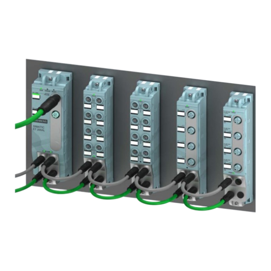
- Page 16 System overview 2.1 What is the SIMATIC ET 200AL distributed I/O system? Configuration example The figure below shows a configuration example of the SIMATIC ET 200AL distributed I/O system with a PROFINET interface module. ① Interface module (PROFINET) ② Digital input/Digital output module ③...
- Page 17 System overview 2.2 Components Components Components of the ET 200AL distributed I/O system The following table shows and explains the function of the most important components of the ET 200AL distributed I/O system. Table 2- 1 Components of the ET 200AL distributed I/O system Components Function View...
- Page 18 Application planning Hardware configuration Mechanical maximum configuration The following tables show the rules of the mechanical configuration. As soon as one of the following rules applies, the maximum configuration has been reached. Table 3- 1 Maximum mechanical configuration - on ET 200AL interface module Properties Rule (max.) Interface modules as...
- Page 19 Application planning 3.1 Hardware configuration Electrical maximum configuration The number of usable I/O modules of a potential group is limited by the following points: ● Power requirements of the I/O modules ● Power requirements of the components supplied via these I/O modules The maximum infeed current of the I/O modules is 4 A with 1L+ supply voltage (non- switched) and 2L+ load voltage (switched).
- Page 20 Application planning 3.2 Configuration variants with ET-Connection Configuration variants with ET-Connection 3.2.1 ET 200AL with ET-Connection Every ET 200AL interface module has 2 ET-Connection connections From every ET-Connection, you have the option to set up a line with a maximum of 16 ET 200AL I/O modules.
- Page 21 Application planning 3.2 Configuration variants with ET-Connection ET-Connection1 and ET-Connection2 The figure below shows a configuration in the IP65/IP67 environment with two ET- Connection lines Figure 3-2 ET 200AL with ET-Connection1 and ET-Connection2 Distributed I/O system System Manual, 02/2018, A5E31861578-AF...
- Page 22 Application planning 3.2 Configuration variants with ET-Connection 3.2.2 Hybrid configuration ET 200AL/ET 200SP with ET-Connection Hybrid configuration ET 200AL and ET 200SP You have the option to integrate the I/O modules of the ET 200AL distributed I/O system (IP65/IP67) in a configuration of the ET 200SP distributed I/O system (IP20). The figure below shows a combination of the modules of the ET 200AL and ET 200SP distributed I/O systems.
- Page 23 Application planning 3.2 Configuration variants with ET-Connection Requirement For a hybrid configuration, you need at least the following components: ● Interface module – IM 155-6 PN HF (V3.0 or higher) – IM 155-6 PN ST (V3.1 or higher) – IM 155-6 DP HF (V3.0 or higher) Note Using 15 m cable Keep in mind that you can only use cables with a cable length of 15 m between the...
- Page 24 Application planning 3.2 Configuration variants with ET-Connection Procedure Watch video sequence (https://support.industry.siemens.com/cs/ww/en/view/95886672) Proceed as follows to put together a multi-tier configuration: 1. Mount the BaseUnit BU-Send directly to the right of the ET 200SP interface module or the ET 200SP CPU.
- Page 25 Mounting Basics Introduction All the modules of the ET 200AL distributed I/O system are designed for the degree of protection IP65/IP67. This means that you can directly mount this system in your plant. Installation position You can mount the ET 200AL distributed I/O system in any position. Minimum clearances At ambient temperatures of 50 °C or higher, please ensure that the module is mounted at a distance of least 1 cm from an adjacent module or another device.
- Page 26 Mounting 4.2 Mounting modules Mounting modules Introduction The modules of the ET 200AL distributed I/O system are designed for installation on a level, firm surface. Thanks to the axisymmetrical drill holes in the modules, you have the option to fasten the modules on an aluminum profile using tee nuts.
- Page 27 ● The distance between the top and bottom drill hole is identical for all modules. Mounting interface module and 45 mm I/O modules (front) Watch video sequence (https://support.industry.siemens.com/cs/ww/en/view/59193566) The interface modules and the 45 mm I/O modules have an attachment point on top and on the bottom.
- Page 28 4.2 Mounting modules Mounting 30 mm I/O modules (front or side) Watch video sequence (https://support.industry.siemens.com/cs/ww/en/view/59193566) The 30 mm I/O modules have an attachment point on top and on the bottom. You also have the option of fastening the 30 mm I/O modules at the side. When fastening them at the side, you must use the supplied spacers.
- Page 29 Mounting 4.2 Mounting modules Fastening for cable ties All module of the ET 200AL distributed I/O system have an integrated attachment point for cable ties. The attachment points are found on all four corners of the modules. The figure below shows the top left attachment point for 2.5 mm wide cable ties for fastening the cables.
- Page 30 Connecting Rules and regulations for operation Introduction Depending on the area of application, the ET 200AL distributed I/O system, as a component of plants and systems, requires that special rules and specifications be followed. This section gives an overview of the most important rules to be followed for integration of the ET 200AL distributed I/O system in a plant or in a system.
- Page 31 If there is a danger due to overvoltages, you must take lightning protection measures for internal lightning protection (e.g. lightning protection elements. You will find additional information in the Designing interference-free controllers (https://support.industry.siemens.com/cs/ww/en/view/59193566) function manual). ● For 24 V DC supply: Ensure that there is a safe (electrical) separation of low voltage (SELV/PELV) according to IEC 60364-4-41.
- Page 32 Connecting 5.2 Operation of the ET 200AL on grounded/non-grounded infeed Operation of the ET 200AL on grounded/non-grounded infeed Introduction Information is provided below on the overall configuration of an ET 200AL distributed I/O system on a grounded incoming supply (TN-S network). The specific subjects discussed are: ●...
- Page 33 Connecting 5.2 Operation of the ET 200AL on grounded/non-grounded infeed ET 200AL in the overall configuration The figure below shows the ET 200AL distributed I/O system in the complete electrical configuration using the example of an interface module. ① Main switch ②...
- Page 34 Connecting 5.2 Operation of the ET 200AL on grounded/non-grounded infeed Components and protective measures Various components and protective measures are stipulated for setting up a complete plant. The types of components and the degree to which the protective measures are mandatory depend on the IEC regulation that applies to your plant setup.
- Page 35 Connecting 5.3 Electrical configuration of the ET 200AL Electrical configuration of the ET 200AL Electrical isolation When electrically configuring the ET 200AL distributed I/O system, there is electrical isolation between: ● Load voltage 2L+ and all other switching parts ● Communication interfaces (PROFINET/PROFIBUS) of the interface modules and all other switching parts ●...
- Page 36 Connecting 5.3 Electrical configuration of the ET 200AL Figure 5-3 Potential conditions of the ET 200AL distributed I/O system (Part 2) Connection of a digital output with a digital input WARNING Pay attention to the potential group When a digital output is connected to a digital input, pay attention to the potential groups. Depending on the configuration, 1M and 2M may then be connected, resulting in elimination of the electrical isolation between 1L+ and 2L+.
- Page 37 Connecting 5.3 Electrical configuration of the ET 200AL Cable protection According to IEC 60364, cable protection is required, i.e. you must always secure the incoming lines externally. You must secure all incoming supply voltages with a UL/IEC approved 24 V DC/4 A fuse (trigger characteristic type B or C).
- Page 38 Connecting 5.4 Connecting ET 200AL to functional earth Connecting ET 200AL to functional earth Introduction You must connect the distributed I/O system ET 200AL to functional earth (FE) What is functional earth? All ET 200AL modules feature a functional earth connection. This connection is used to suppress interference sensitivity, but not for protection purposes.
- Page 39 Connecting 5.4 Connecting ET 200AL to functional earth Mounting To connect modules of the ET 200AL distributed I/O system to functional earth with a conductive mounting substrate, proceed as follows: 1. Drill two fastening holes. 2. Screw the module with the M4 fastening screws using a torque of 1.2 Nm. Note Earthing with conductive mounting substrate When you fasten a module of the ET 200AL distributed I/O system on a conductive,...
- Page 40 Connecting 5.4 Connecting ET 200AL to functional earth Mounting To connect modules of the ET 200AL distributed I/O system to functional earth, proceed as follows: 1. Drill two fastening holes. 2. Strip the grounding cable. 3. Fasten the cable lug to the grounding cable. 4.
- Page 41 Connecting 5.5 Connecting cables for ET 200AL Connecting cables for ET 200AL Impact of cable length on the supply voltage When wiring your configuration, you must take into account the impact of the cable length on the supply voltage of the ET 200AL distributed I/O system. CAUTION Pay attention to maximum incoming currents For each power supply (1L+, 2L+), you can feed in a maximum of 4A.
- Page 42 Connecting 5.6 Wiring Wiring Connection Connect all cables to the front side of the modules: ● Supply voltage and ET-Connection to the 4-pole M8 round sockets and M8 round connectors ● Signal lines to the 3-pole M8 or 4/5-pole M12 round sockets ●...
- Page 43 Connecting 5.6 Wiring Connecting M8 connectors To connect M8 connectors, proceed as follows: 1. Insert the connector in the appropriate round socket on the module. Make sure that there is proper locking between the connector and socket. 2. Tighten the connector using the knurled screw with a torque of 0.4 Nm. The figure below shows the connection of the M8 connectors, using the example of the DIQ 4+DQ 4x24VDC/0.5A 8xM8 digital input/ digital output module.
- Page 44 Pin assignment of the sockets The pin assignment of the sockets can be found in the manuals for the interface modules (https://support.industry.siemens.com/cs/ww/en/ps/14246/man) and I/O modules (https://support.industry.siemens.com/cs/ww/en/ps/14247/man) in the section on pin assignment and on the side surface of the module. Distributed I/O system...
- Page 45 Connecting 5.6 Wiring Y-cable The Y-cable allows you to connect two actuators or sensors to the inputs or outputs. The use of a Y-cable is particularly recommended when two channels are occupied for each socket of an I/O device. The Y-cable distributes the channels to two circular connectors. The figure below shows the wiring of the Y-cable.
- Page 46 Connecting 5.7 ET 200AL marking ET 200AL marking 5.7.1 Factory markings Introduction For better orientation, the ET 200AL distributed I/O system is identified using various markings which will help you when configuring and connecting the modules. Marking of the interfaces The interfaces of the modules are factory-labeled.
- Page 47 Connecting 5.7 ET 200AL marking 5.7.2 Optional markings Introduction In addition to the factory markings, there are also optional possibilities for labeling and/or identifying interfaces and modules on the ET 200AL distributed I/O system. Identification label The identification labels come with each module as strips and can be machine-printed. A strip has 10 identification labels measuring 10 x 5 mm in the color RAL9016.
- Page 48 Connecting 5.7 ET 200AL marking Required tools You need a screwdriver with 3 mm blade width (only to remove identification labels). Mounting procedure To mount an identification label, proceed as follows: 1. Print the identification label using commercially available marking systems. 2.
- Page 49 Configuring Introduction You configure and assign parameters for the ET 200AL distributed I/O system (interface modules and I/O modules) using STEP 7 or the configuration software of another manufacturer. Requirements Table 6- 1 Configuration software and requirements Configuration software Requirements Installation information STEP 7 (TIA Portal) as of V14 STEP 7 online help...
- Page 50 PROFINET IO, PROFIBUS DP: • IO modules as of Support Package HSP 0260 STEP 7 (TIA Portal) as of V13 PROFINET IO • Update 3 GSD file: GSDML-Vx.y-Siemens- Software of third-party manufac- ET200AL-"Date in format Manufacturer docu- turer mentation yyyymmdd".xml (https://support.industry.siemens.com/ cs/ww/en/view/92346477) for example: GSDML-V2.31-Siemens-...
- Page 51 Configuring The figure below shows the maximum configuration with modules of the ET 200AL distributed I/O system. Figure 6-1 PROFINET maximum configuration Reference You can find additional information on this topic in section Configuration control (option handling) (Page 51). Configuration - PROFIBUS maximum configuration Each of the connections for ET-Connection occupies a slot in the configuration.
- Page 52 Configuring The figure below shows the maximum configuration with modules of the ET 200AL distributed I/O system. Figure 6-2 PROFIBUS maximum configuration Reference You can find additional information on this topic in section Configuration control (option handling) (Page 51). Distributed I/O system System Manual, 02/2018, A5E31861578-AF...
- Page 53 Configuration control (option handling) Configuration control Introduction With configuration control (option handling), you handle various standard machine configuration levels in one project without having to change the hardware configuration or user program. Operating principle of configuration control You can use configuration control to operate different standard machine configurations with a single configuration of the ET 200AL distributed I/O system.
- Page 54 Configuration control (option handling) 7.1 Configuration control The following figure shows 3 configurations of a standard machine with the corresponding station options of the ET 200AL distributed I/O system. Figure 7-1 Various configuration levels of a standard machine with the corresponding station options of the ET 200AL distributed I/O system.
- Page 55 Block library "OH_S71x00_Library" The block library OH_S71x00_Library (https://support.industry.siemens.com/cs/ww/en/view/29430270) is available for download from the Internet. The block library contains data types with the structure of the control data records for the ET200AL distributed I/O system. You can implement your flexible automation solution economically with the help of these data types.
- Page 56 Configuration control (option handling) 7.2 Configuring Configuring Requirements Via PROFINET IO: ● Configuration software, for example STEP 7 Professional as of V13 ● IM 157-1 PN ● You have assigned the interface module to an IO controller in STEP 7 Via PROFIBUS DP: ●...
- Page 57 Configuration control (option handling) 7.2 Configuring Required steps Enable the "Allow to reconfigure the device via the user program" parameter when configuring the interface module. ● The parameter "Enable reconfiguration of device via user program" is located in the properties of the interface module under "Module parameters" > "Configuration control". Figure 7-2 Enabling configuration control using the IM 157-1 PN as an example Distributed I/O system...
- Page 58 Configuration control (option handling) 7.3 Creating the control data record Creating the control data record 7.3.1 Introduction Required steps The following description shows as an example how you can create a control data record for the configuration control in STEP 7 (TIA Portal). To create a control data record for the configuration control, follow these steps: 1.
- Page 59 Configuration control (option handling) 7.3 Creating the control data record 3. Create an array of the data type of the above created PLC data type in the data block. The following figure shows a data block containing the control data records for an ET200AL interface module.
- Page 60 Configuration control (option handling) 7.3 Creating the control data record Rules Observe the following rules: ● Slot entries in the control data record outside the station master are ignored by the interface module. ● The control data record must contain the entries up to the last slot of the station option. ●...
- Page 61 Configuration control (option handling) 7.3 Creating the control data record Control data record For configuration control of the ET 200AL distributed I/O system you define a control data record 196 V2.1, which contains a slot assignment for the modules. The table below shows the structure of a control data record with explanations of the individual elements.
- Page 62 You have moved the DQ module to Slot 2 in the station option. In order to set up PROFIenergy for this module use Slot 2 in Data record 3. You can find more information about PROFIenergy in the Interface module IM 157-1 PN (https://support.industry.siemens.com/cs/ww/en/view/89254863) Equipment Manual. 7.3.3 Feedback data record at the ET200AL distributed I/O system...
- Page 63 Configuration control (option handling) 7.3 Creating the control data record Note The data in the feedback data record is always mapped for all modules. In a Shared Device configuration, it is therefore irrelevant which IO controller the respective modules are assigned to.
- Page 64 Configuration control (option handling) 7.3 Creating the control data record Figure 7-6 Example: Hardware configuration of Station option 2 and 4 with the associated control data record in STEP 7 Distributed I/O system System Manual, 02/2018, A5E31861578-AF...
- Page 65 Configuration control (option handling) 7.3 Creating the control data record Extension by a station option The following figure shows the configuration with the Station options 2 and 4 that has subsequently been extended by the Station option 3. The modules of option 3 are added to the modules already existing. Figure 7-7 Example: Hardware configuration of station option 2 to 4 with the associated control data record in STEP 7...
- Page 66 You can find a detailed application example for the configuration control in S7-1500 in here under the keyword "Application example for ET 200SP (PROFINET) and S7-1500 based on the library" on the Internet (https://support.industry.siemens.com/cs/ww/en/view/29430270). Transferring the control data record in the user program of the CPU...
- Page 67 Configuration control (option handling) 7.4 Transferring the control data record in the user program of the CPU Special requirements relating to the transfer of the control data record to the interface module ● If you have enabled configuration control, the ET 200AL station is not ready for operation without a control data record.
- Page 68 Configuration control (option handling) 7.5 Behavior during operation Behavior during operation Effect of discrepancy between station master and station option For the online display and for the display in the diagnostics buffer (module OK or module faulty), the station master is always used and not the differing station option. Example: A module outputs diagnostics data.
- Page 69 ET 200AL interface module automatically switches to RUN mode Reference You can find additional information on assigning the PROFINET IO parameters in the PROFINET with STEP 7 V14 (https://support.industry.siemens.com/cs/ww/en/view/49948856) function manual. Distributed I/O system System Manual, 02/2018, A5E31861578-AF...
- Page 70 Commissioning 8.1 PROFINET IO 8.1.2 Startup on PROFINET IO Principle of operation The figure below schematically shows the startup of the ET 200AL distributed I/O system on the PROFINET IO (= IO device) as a flow chart. Figure 8-1 Startup of the ET 200AL distributed I/O system on the PROFINET IO Distributed I/O system System Manual, 02/2018, A5E31861578-AF...
- Page 71 Commissioning 8.1 PROFINET IO The figure below schematically shows the startup of an ET 200AL I/O module after an ET 200AL PROFINET interface module. Figure 8-2 Startup of the ET 200AL I/O module Distributed I/O system System Manual, 02/2018, A5E31861578-AF...
- Page 72 Application Profile PROFIenergy; Technical Specification for PROFINET; as well as in the following documentation: ● IM 157-1 PN interface module (https://support.industry.siemens.com/cs/ww/en/view/89254863) manual ● I/O modules (https://support.industry.siemens.com/cs/ww/en/ps/14247/man) manuals ● PROFINET System Description (https://support.industry.siemens.com/cs/ww/en/view/19292127) system manual ● PROFINET with STEP 7 V14 (https://support.industry.siemens.com/cs/ww/en/view/49948856), function manual,...
- Page 73 Section Mounting (Page 23) Setting the PROFIBUS DP address on the IM 157-1 DP interface module ET 200AL PROFIBUS interface module (https://support.industry.siemens.com/cs/ww/en /view/89255073) manual, section Setting the PROFIBUS DP address and terminating resis- Wiring the ET 200AL interface module Section Connecting (Page 28)
- Page 74 Commissioning 8.2 PROFIBUS DP 8.2.2 Startup on PROFIBUS DP Principle of operation The figure below schematically shows the startup of the ET 200AL distributed I/O system on the PROFIBUS DP (= DP slave) as a flow chart. Figure 8-3 Startup of the ET 200AL distributed I/O system on PROFIBUS DP Distributed I/O system System Manual, 02/2018, A5E31861578-AF...
- Page 75 Commissioning 8.2 PROFIBUS DP The figure below schematically shows the startup of an ET 200AL I/O module after an ET 200AL PROFIBUS interface module as flow chart. Figure 8-4 Startup of an ET 200AL I/O module Distributed I/O system System Manual, 02/2018, A5E31861578-AF...
- Page 76 Commissioning 8.3 Identification and maintenance data Identification and maintenance data 8.3.1 Reading out and entering I&M data Introduction Identification data I&M is information that is saved either as read-only (I data) or read/write (M data) on the interface module. Identification data (I&M0): Manufacturer information on the module that is read-only and in some cases is also printed on the module housing, for example, article number, serial number and firmware version.
- Page 77 During the loading of the hardware configuration, the I&M data are also loaded. Reference You can find additional information on I&M data of the ET 200SP (mixed configuration) in the ET 200SP distributed I/O system (https://support.industry.siemens.com/cs/ww/en/view/58649293) system manual. Distributed I/O system System Manual, 02/2018, A5E31861578-AF...
- Page 78 Commissioning 8.3 Identification and maintenance data 8.3.2 Data record structure for I&M data Reading I&M data records (distributed via PROFINET IO) You can directly access specific identification data by selecting Read data record ("RDREC" instruction). You obtain the corresponding part of the identification data under the associated data record index.
- Page 79 Explanation Identification data 0: (data record index AFF0 hex) VendorIDHigh read (1 byte) This is where the name of the manufac- turer is stored (42 = SIEMENS AG). VendorIDLow read (1 byte) Order_ID read (20 bytes) 6ES7157-1AB00-0AB0 Order number of the module (e.g. of...
- Page 80 Maintenance Replacing modules Replacing modules Replacing a module is not permitted during ongoing operation. WARNING Material damage can occur If you remove/insert modules with the power connected, this can lead to undefined states in your system. Material damage to the ET 200AL distributed I/O system may occur as a result. Only remove or replace modules when the power is disconnected.
- Page 81 Maintenance 9.1 Replacing modules 4. Replace the module. Note "New" module The removed module may only be replaced by a module of the same type. 5. Fasten the module with a torque of 1.2 Nm. 6. Connect all cables. 7. Turn the supply voltage on. WARNING Pay attention to the slot number of the module If you mix up the ET 200AL I/O modules when connecting them, this can cause personal...
- Page 82 ● Online with STEP 7, TIA Portal V13 or higher Reference You can find additional information on the procedure in the FAQs on the Internet (https://support.industry.siemens.com/cs/ww/en/view/88778936) and in the online help for STEP 7. Distributed I/O system System Manual, 02/2018, A5E31861578-AF...
- Page 83 Maintenance 9.3 Resetting interface module to factory settings (PROFINET) Resetting interface module to factory settings (PROFINET) Introduction When you "Reset to factory settings", the interface module is reset to the delivery state settings. This means that all information that was saved internally on the interface module is deleted.
- Page 84 Maintenance 9.4 Cleaning modules Requirement You need an online connection to reset an interface module to factory settings. Procedure with STEP 7 (TIA Portal) Connect the PG/PC to the PROFINET IO interface of the ET 200AL distributed I/O system. Make sure that there is an online connection to the interface module which is to be reset to factory settings.
- Page 85 Maintenance 9.4 Cleaning modules Cleaning modules When wired, ET 200AL modules comply with degree of protection IP65/IP67 and do not require any cleaning. If you do have to clean the modules, then use a dry or damp cloth. Please take care to comply with degree of protection IP65/67 when cleaning with liquids. Distributed I/O system System Manual, 02/2018, A5E31861578-AF...
- Page 86 Reference The certificates for the markings and approvals can be found on the Internet (https://support.industry.siemens.com). Distributed I/O system System Manual, 02/2018, A5E31861578-AF...
- Page 87 ● 2014/30/EU "Electromagnetic Compatibility" (EMC directive) ● 2011/65/EU "Restriction of the use of certain hazardous substances in electrical and electronic equipment" (RoHS Directive) The EC declarations of conformity are available to the responsible authorities at: Siemens AG Digital Factory Factory Automation DF FA AS SYS...
- Page 88 Technical specifications 10.1 Standards and authorizations Korea Certificate KCC-REM-S49-ET200 Please note that this device corresponds to limit class A with regard to the emission of radio interference. This device can be used in all areas, except residential areas. 이 기기는 업무용(A급) 전자파 적합기기로서 판매자 또는 사용자는 이 점을 주의하시기 바라며...
- Page 89 ET 200AL distributed I/O system in residential areas, radio and TV reception may be affected. Reference The certificates for the markings and approvals can be found on the Internet under Service&Support (http://www.siemens.com/automation/service&support). Distributed I/O system System Manual, 02/2018, A5E31861578-AF...
- Page 90 Technical specifications 10.2 Electromagnetic compatibility 10.2 Electromagnetic compatibility Definition Electromagnetic compatibility is the ability of an electrical apparatus to function in a satisfactory manner in its electromagnetic environment without affecting this environment. An I/O device of the ET 200AL distributed I/O system fulfills the requirements of the EMC law of the European Union.
- Page 91 Technical specifications 10.2 Electromagnetic compatibility Sinusoidal disturbance variables The following tables show the electromagnetic compatibility of the distributed I/O systems to sinusoidal disturbance variables. Table 10- 2 RF radiation RF radiation according to IEC 61000-4-3 Corresponds to de- Electromagnetic RF field, amplitude modulated gree of severity 80 to 1000 MHz 10 V/m...
- Page 92 Technical specifications 10.3 Transport and storage conditions 10.3 Transport and storage conditions Transport and storage conditions The modules of the ET 200AL distributed I/O system exceed the specifications regarding transport and storage conditions pursuant to IEC 61131-2. The following table shows the conditions that apply to modules transported or stored in their original packaging.
- Page 93 Technical specifications 10.4 Mechanical and climatic ambient conditions 10.4 Mechanical and climatic ambient conditions Operating conditions The ET 200AL distributed I/O system is suitable for use in weather-proof, fixed locations. The conditions of use exceed the requirements pursuant to IEC 60721-3-3: ●...
- Page 94 Technical specifications 10.5 Details on insulation, protection class, degree of protection and rated voltage 10.5 Details on insulation, protection class, degree of protection and rated voltage Insulation The insulation is designed in compliance with the requirements of IEC 61010-2-201. Note Galvanic isolation with 707 V DC (Type Test) is tested for modules with 24 V DC supply voltage (SELV/PELV).
- Page 95 Technical specifications 10.6 Safety-related symbols for IP65/IP67 modules 10.6 Safety-related symbols for IP65/IP67 modules The following table contains an explanation of the symbols located on your IP65/67 modules, their packaging or in the accompanying documentation. Symbol Meaning General warning sign Caution/Notice You must read the product documentation.
- Page 96 Safety-related shutdown of ET200AL standard modules Introduction The diagram below illustrates the fail-safe shutdown of ET 200AL standard modules. In the configuration shown in the diagram below, all digital outputs that are operated with the 2L+ and 2M supply of the ET 200AL standard modules are switched to the safe OFF state. This step achieves the safety class SIL2/category 3/PLd.
- Page 97 Digital Factory DF FA AS SYS P.O. Box 1963 D-92209 Amberg, Germany Reference You can find additional information as well as an overview of the modules with safety-related shutdown on the Internet (https://support.industry.siemens.com/cs/us/en/view/39198632). Distributed I/O system System Manual, 02/2018, A5E31861578-AF...
- Page 98 40 mm to 46 mm. Detailed information on the dimensions of the individual modules can be found in the manuals for the Interface modules (https://support.industry.siemens.com/cs/ww/en/ps/14246/man) and I/O modules (https://support.industry.siemens.com/cs/ww/en/ps/14247/man) in the section "Dimension drawing". Figure B-1 Module dimension drawings (front view)
- Page 99 Accessories/spare parts Accessories/spare parts Accessories for the ET 200AL distributed I/O system Table C- 1 Accessories for ET-Connection Designation Length Article number Cable Standard Bus cable for ET-Connection M8, pre-assembled on 0.19 m 6ES7194-2LH02-0AA0 6ES7194-2MH02-0AA0 both sides with 2 x M8 connectors, 4-pole, shielded 0.3 m 6ES7194-2LH03-0AA0 6ES7194-2MH03-0AA0...
- Page 100 Accessories/spare parts C.1 Accessories/spare parts Table C- 2 Accessories for power supply Designation Length Article number Cable Standard Power cable M8, pre-assembled on both sides with 0.19 m 6ES7194-2LH02-1AA0 6ES7194-2MH02-1AA0 M8 connector and M8 socket, 4-pole 0.3 m 6ES7194-2LH03-1AA0 6ES7194-2MH03-1AA0 1.0 m 6ES7194-2LH10-1AA0 6ES7194-2MH10-1AA0...
- Page 101 Accessories/spare parts C.1 Accessories/spare parts Table C- 3 M12 connector Designation Article number Non-preassembled connectors for X1 DP1 (pin) PROFIBUS M12 plug connector 180° with female insert 6GK1905-0EB00 PROFIBUS M12 plug connector FastConnect 180° with female 6GK1905-0EB10 insert PROFIBUS M12 plug connector, angled with female insert 3RK1902-1DA00 Non-preassembled connectors for X1 DP2 (socket) PROFIBUS M12 plug connector 180°...
- Page 102 Accessories/spare parts C.1 Accessories/spare parts Table C- 5 Pre-assembled cable M12 Designation Article number Pre-assembled cable for X1 DP1 and X1 DP2 PROFIBUS M12 connecting cable, trailing cable, pre- 0.3 m 6XV1830-3DE30 assembled on both sides with PROFIBUS M12 con- 0.5 m 6XV1830-3DE50 nectors, 180°...
- Page 103 Stripping Tool for PROFIBUS 6GK1905-6AA00 Online catalog Other article numbers for the ET 200AL distributed I/O system can be found on the Internet (https://mall.industry.siemens.com) in the online catalog and the online order system. Distributed I/O system System Manual, 02/2018, A5E31861578-AF...
- Page 104 Accessories/spare parts C.2 Cables Cables Cables for ET-Connection standard and PUR cable The cables for ET-Connection are available in the following versions and lengths: ● Bus cable (4-wire), pre-assembled on both sides with 2 M8 connectors, 4-pole, shielded – available lengths: 0.19 m, 0.3 m, 1 m, 2 m, 5 m, 10 m, 15 m ●...
- Page 105 Accessories/spare parts C.2 Cables General information One time bending, min. 20 mm Multiple bending, min. 40 mm Constant bending 100 mm Color of the cable sheath Green Color of the wire insulation of the data wires White, yellow, blue, orange Weight per length 34 kg/km Mechanics/material...
- Page 106 Accessories/spare parts C.2 Cables General information Outside diameter of the cable sheath 5 mm Number of bending cycles 1000000*; trailing-chain suitable for 1 million bending cycles with a bending radius of 100 mm, a velocity of 4 m/s and an acceleration of 4 m/s² Permissible bending radius One time bending, min.
- Page 107 Accessories/spare parts C.2 Cables The following table shows the technical properties of the connecting cable for ET-Connection standard. Table C- 10 Connecting cables for ET-Connection General information Product type designation CONNECTING CABLE FOR BUS CABLE ET- CONNECTION, CABLE 0.2 M Function To connect two bus cables ET-CONNECTION Degree of protection and protection class...
- Page 108 Accessories/spare parts C.2 Cables The following table shows the technical properties of the connecting cable for ET- Connection, PUR cable. Table C- 11 Connecting cables for ET-Connection, PUR cable General information Product type designation CONNECTING CABLE FOR BUS CABLE ET- CONNECTION, PUR CABLE 0.2 M Function To connect two bus cables ET-CONNECTION...
- Page 109 Accessories/spare parts C.2 Cables Cables of power supply standard and PUR cable The cables for the power supply are available in the following versions and lengths: ● Power cable (4-wire), pre-assembled on both sides with a 4-pole M8 pin connector/socket connector –...
- Page 110 Accessories/spare parts C.2 Cables General information Color of the wire insulation of the power wires White, brown, blue black Weight per length 44 kg/km Mechanics/material Type of cable outlet 180° cable outlet 90° cable outlet (with angled connectors) Number of connectors 1 or 2 Connector housing material Plastic...
- Page 111 Accessories/spare parts C.2 Cables General information Color of the cable sheath gray Color of the wire insulation of the power wires White, brown, blue black Weight per length 44 kg/km Mechanics/material Type of cable outlet 180° cable outlet 90° cable outlet (with angled connectors) Number of connectors 1 or 2 Connector housing material...
- Page 112 Accessories/spare parts C.3 Pin assignment and core color Pin assignment and core color Pin assignment of the sockets for ET-Connection The tables below shows the pin assignments of the 2 sockets for the connection of ET-Connection. Table C- 14 Pin assignment for ET-Connection (interface modules) Assignment Assignment of the Front view of the sockets...
- Page 113 Accessories/spare parts C.3 Pin assignment and core color Pin assignment of the socket for loop-through of the supply voltage The table below shows the pin assignment for loop-through of the supply voltage. Table C- 17 Pin assignment of the supply voltage socket Assignment Assignment of the Front view of the...
- Page 114 Glossary A common transfer route to which all devices are connected; it has two defined ends. Configuration Systematic arrangement of individual modules (design). Connection plug Physical connection between device and cable. Device Device that can send, receive or amplify data via the bus, e.g. IO device via PROFINET IO. Diagnostics Monitoring functions for the detection, localization, classification, display, and further evaluation of errors, faults, and alarms.
- Page 115 Glossary Ground Conductive earth whose electrical potential can be set equal to zero at any point. All interconnected, inactive parts of a piece of equipment that cannot accept any dangerous contact voltage, even in the event of a fault. Ground Conductive earth whose electrical potential can be set equal to zero at any point.
- Page 116 Glossary PROFINET IO controller Device used to address connected I/O devices (e.g. distributed I/O systems). This means that: The IO controller exchanges input and output signals with assigned I/O devices. The IO controller often corresponds with the CPU in which the automation program is running. PROFINET IO device Distributed field device that can be assigned to one or more IO controllers (e.g.
- Page 117 Index ET-Connection1 and ET-Connection2, 19 Hybrid configuration, 20 Configuring, 47 Connecting 24 V DC supply, 29 Conductive substrate, 37 M12 connectors, 42 M8 connectors, 41 Non-conductive substrate, 38 Accessories, 97 Connecting cables, 39 Ambient conditions Climatic, 91 Mechanical, 91 Application, 28 Degree of protection, 92 Approvals, 85 Dimension drawing...
- Page 118 Safe electrical isolation, 30 Line voltage, 29 Safety relay, 94 Screws, 24 SELV, 30 Setup, 13 Shock, 91 M12 connectors, 42 SIMATIC ET 200AL, 12 M8 connectors, 41 Sinusoidal disturbance variables, 89 Maintenance, 78 Slot number, 79 Maintenance data, 74 Sockets, 43 Marking...
- Page 119 Index in industrial environments, 87 in mixed areas, 87 in residential areas, 87 Vibrations, 91 Wires, 28 Distributed I/O system System Manual, 02/2018, A5E31861578-AF...
- Page 120 ___________________ Product Information Mixed Preface Configuration ET 200SP / ET 200AL ___________________ Application planning ___________________ SIMATIC Mounting ___________________ Connection ET 200SP Product Information Mixed ___________________ Configuring Configuration ET 200SP / ET 200AL ___________________ BaseUnit BU-Send Product Information ___________________ BusAdapter BA-Send 1xFC 02/2016 A5E33344611-AC...
- Page 121 Note the following: WARNING Siemens products may only be used for the applications described in the catalog and in the relevant technical documentation. If products and components from other manufacturers are used, these must be recommended or approved by Siemens. Proper transport, storage, installation, assembly, commissioning, operation and maintenance are required to ensure that the products operate safely and without any problems.
- Page 122 This product information supplements the ET 200SP system manual documentation. Security information For the secure operation of Siemens products and solutions, it is necessary to take suitable preventive action (e.g. cell protection concept) and integrate each component into a holistic, state-of-the-art industrial security concept.
- Page 123 Table of contents Preface ..............................3 Application planning ..........................5 Mounting ..............................8 Connection ............................. 9 Configuring ............................13 BaseUnit BU-Send ..........................17 Product overview........................17 Connection ..........................18 Technical specifications ......................19 BusAdapter BA-Send 1xFC ........................20 Properties ..........................20 Pin assignment........................
- Page 124 Application planning Mixed configuration ET 200SP and ET 200AL with ET-Connection You have the option of integrating the I/O modules of the ET 200AL distributed I/O system (IP65/IP67) in a configuration of the ET 200SP distributed I/O system (IP20). The figure below shows a combination of the modules of the ET 200AL and ET 200SP distributed I/O system.
- Page 125 Application planning Requirement The following components support mixed configuration: ● Interface module – IM 155-6 PN HF (V3.0 or higher) – IM 155-6 PN ST (V3.1 or higher) – IM 155-6 DP HF (V3.0 or higher) ● CPU – CPU 1510SP-1 PN (V2.0 or higher) –...
- Page 126 Application planning Procedure To assemble a multi-tier configuration, follow these steps: 1. Install the BaseUnit BU-Send to the immediate right of the ET 200SP CPU/interface module. When the BaseUnit BU-Send is used next to the ET 200SP CPU, a CM DP and an Ethernet CP or a maximum of 2 Ethernet CPs can be inserted between the CPU and BU- Send.
- Page 127 Mounting Introduction For the connection of the ET 200AL I/O module via ET-Connection to the ET 200SP, you require the BaseUnit BU-Send with the BusAdapter BA-Send 1xFC. Requirement ● The mounting rail is mounted. ● The interface module is mounted. Required tools 3 to 3.5 mm screwdriver (only for dismantling the BusAdapter) Mounting BaseUnit BU-Send...
- Page 128 Connection Introduction You connect the ET 200AL I/O modules via the BusAdapter BA-Send 1×FC using ET- Connection. ① BusAdapter BA-Send 1×FC ② Connection element for ET-Connection bus cable Image 3-1 BusAdapter BA-Send 1xFC Required tools Screwdriver with 3 to 3.5 mm blade Required accessories Use the bus cable for ET-Connection as connecting cable between the BusAdapter BA-Send 1xFC and the ET 200AL I/O modules.
- Page 129 Connection Procedure To connect the BusAdapter BA-Send 1xFC, follow these steps: 1. Strip the sheath of the bus cable at the open end as follows: Image 3-2 Connecting cable Use the stripping tool for ET-Connection to do this. The relevant settings are shown on the tool.
- Page 130 Connection 6. Connect and screw the BusAdapter BA-Send 1×FC to the BaseUnit BU-Send (1 screw with 0.2 Nm tightening torque.) To do this, use a screwdriver with a 3 to 3.5 mm blade. 7. Connect the M8 connector of the bus cable to the first ET 200AL I/O module (socket X30 ET-Connection IN).
- Page 131 Connection BusAdapter BA-Send 1×FC mounted ① BusAdapter BA-Send 1×FC ② Bus cable for ET-Connection Image 3-4 BusAdapter BA-Send 1×FC mounted Product Information Mixed Configuration ET 200SP / ET 200AL Product Information, 02/2016, A5E33344611-AC...
- Page 132 Configuring Introduction The mixed configuration allows the connection of up to 16 ET 200AL I/O modules to the ET 200SP via ET-Connection. The figure below shows the configuration of the ET-Connection and the assignment of the slots. ① ⑤ ET 200SP I/O modules 1st ET 200AL I/O module ②...
- Page 133 Configuring Rules Observe the following rules when configuring: ● With mixed configurations, the following maximum configuration is possible: – 31 (IM 155-6 DP HF and IM 155-6 PN ST)/63 (IM 155-6 PN HF and CPUs) slots for ET 200SP modules –...
- Page 134 Configuring Configuration example An example of a mixed configuration is shown below: Hardware configuration ① ⑥ ET 200SP I/O modules 2nd ET 200AL I/O module ② ⑦ ET 200SP server module 3rd ET 200AL I/O module ③ ⑧ Slots 4th ET 200AL I/O module ④...
- Page 135 Configuring Configuring configuration example Table 4- 1 Overview Mixed configura- Module Slot tion ET 200SP IM 155-6 PN HF BA-Send 1xFC DI 16×24VDC ST DI 16×24VDC ST DI 16×24VDC ST Server module ET 200AL DI 8x24VDC 8xM8 DIQ 4+DQ 4x24VDC/0.5A 8xM8 AI 4xU/I/RTD 4xM12 CM 4xIO-Link 4xM12 Note...
- Page 136 BaseUnit BU-Send Product overview Article number 6ES7193-6BN00-0NE0 View Image 5-1 BaseUnit BU-Send Properties BaseUnit suitable for BusAdapter BA-Send 1xFC Product Information Mixed Configuration ET 200SP / ET 200AL Product Information, 02/2016, A5E33344611-AC...
- Page 137 BaseUnit BU-Send 5.2 Connection Connection Pin assignment The BaseUnit BU-Send has only one slot for an expansion module. No other connections are available. Schematic circuit diagram ① Backplane bus ② BA-Send 1xFC expansion module Image 5-2 Schematic circuit diagram BU-Send Product Information Mixed Configuration ET 200SP / ET 200AL Product Information, 02/2016, A5E33344611-AC...
- Page 138 BaseUnit BU-Send 5.3 Technical specifications Technical specifications Technical specifications of the BaseUnit BU-Send 6ES7193-6BN00-0NE0 Product type designation BaseUnit BU-Send Installation type/mounting Rack mounting possible Front installation possible Rail mounting possible Wall/direct mounting possible Hardware configuration Slots Number of slots Plug-in modules, other Yes;...
- Page 139 BusAdapter BA-Send 1xFC Properties Article number 6ES7193-6AS00-0AA0 View of the module ① Module type and name ② LED for diagnostics ③ ((Connection for ET-CONNECTION)) ④ Article number ⑤ Functional version Image 6-1 View of the BusAdapter BA-Send 1xFC Product Information Mixed Configuration ET 200SP / ET 200AL Product Information, 02/2016, A5E33344611-AC...
- Page 140 See also You can find more information on accessories and additional components in the Accessories/spare parts section of the ET 200AL distributed I/O system (http://support.automation.siemens.com/WW/view/en/89254965) system manual. Product Information Mixed Configuration ET 200SP / ET 200AL Product Information, 02/2016, A5E33344611-AC...
- Page 141 BusAdapter BA-Send 1xFC 6.2 Pin assignment Pin assignment ET-Connection with BusAdapter BA-Send 1xFC The following table shows the signal names and the designations for the pin assignment of the BusAdapter BA-Send 1xFC. Table 6- 1 ET-Connection pin assignment with BusAdapter BA-Send 1×FC View Signal name Description...
- Page 142 BusAdapter BA-Send 1xFC 6.4 Diagnostics by means of LED display Diagnostics by means of LED display LED display The figure below shows the LED display (status and fault display) of the BusAdapter BA- Send 1xFC. ① DIAG (green/red) Image 6-3 LED display Meaning of the LED display The table below explains the meaning of the status and fault display.
- Page 143 BusAdapter BA-Send 1xFC 6.5 Technical specifications DIAG LED Table 6- 2 Status and fault display DIAG DIAG LED Meaning Remedy There is no connection between the Check whether the bus cable is interrupted. ET-Connection interface of the BusAdapter BA-Send 1xFC and ET 200AL.
- Page 145 ___________________ Preface ___________________ Documentation guide ___________________ SIMATIC Product overview ___________________ Wiring ET 200AL Interface module IM 157-1 DP ___________________ (6ES7157-1AA00-0AB0) Parameters ___________ Interrupts, error messages, diagnostics and system Manual alarms ___________________ Technical specifications ___________________ Dimension drawing ___________________ Cycle times 12/2016 A5E32100641-AD...
- Page 146 Note the following: WARNING Siemens products may only be used for the applications described in the catalog and in the relevant technical documentation. If products and components from other manufacturers are used, these must be recommended or approved by Siemens. Proper transport, storage, installation, assembly, commissioning, operation and maintenance are required to ensure that the products operate safely and without any problems.
- Page 147 In order to protect plants, systems, machines and networks against cyber threats, it is necessary to implement – and continuously maintain – a holistic, state-of-the-art industrial security concept. Siemens’ products and solutions only form one element of such a concept. Customer is responsible to prevent unauthorized access to its plants, systems, machines and networks.
- Page 148 Table of contents Preface ..............................4 Documentation guide ..........................6 Product overview ............................ 9 Properties ..........................9 Operator controls and display elements ................. 11 Functions ..........................12 2.3.1 PROFIBUS DP ........................12 2.3.2 Configuration control (option handling) ................... 13 Wiring ..............................14 Terminal and block diagram ....................
- Page 149 Documentation guide The documentation for the SIMATIC ET 200AL distributed I/O system is arranged into three areas. This arrangement enables you to access the specific content you require. Basic information The System Manual and Getting Started describe in detail the configuration, installation, wiring and commissioning of the SIMATIC ET 200AL distributed I/O system.
- Page 150 You must register once to use the full functionality of "mySupport". You can find "mySupport" on the Internet (https://support.industry.siemens.com/My/ww/en). "mySupport" - Documentation In the Documentation area in "mySupport" you can combine entire manuals or only parts of these to your own manual.
- Page 151 With the TIA Selection Tool, you can generate a complete order list from your product selection or product configuration. You can find the TIA Selection Tool on the Internet (http://w3.siemens.com/mcms/topics/en/simatic/tia-selection-tool). Interface module IM 157-1 DP (6ES7157-1AA00-0AB0) Manual, 12/2016, A5E32100641-AD...
- Page 152 Product overview Properties Article number 6ES7157-1AA00-0AB0 View of the module Figure 2-1 View of the IM 157-1 DP interface module Interface module IM 157-1 DP (6ES7157-1AA00-0AB0) Manual, 12/2016, A5E32100641-AD...
- Page 153 ● M12 sealing cap See also You will find additional information on accessories and the other components in the Accessories/Spare parts section of the ET 200AL Distributed I/O System (http://support.automation.siemens.com/WW/view/en/89254965) system manual. Interface module IM 157-1 DP (6ES7157-1AA00-0AB0) Manual, 12/2016, A5E32100641-AD...
- Page 154 Product overview 2.2 Operator controls and display elements Operator controls and display elements The figure below shows the operator control and display elements of the interface module IM 157-1 DP. ① RUN, ERROR, MAINT: LED displays for the current operating status and diagnostics status ②...
- Page 155 DP master and the DP slaves. Reference You will find more information on PROFIBUS DP in the STEP 7 online help and in the Function Manual PROFIBUS with STEP 7 V13 (http://support.automation.siemens.com/WW/view/en/59193579). Interface module IM 157-1 DP (6ES7157-1AA00-0AB0) Manual, 12/2016, A5E32100641-AD...
- Page 156 Reference You can find more information on configuration control ● In the system manual ET 200AL Distributed I/O System (https://support.industry.siemens.com/cs/ww/en/view/89254965) ● On the Internet under the following link: Application collection (https://support.industry.siemens.com/cs/ww/en/view/29430270). ● In the STEP 7 online help.
- Page 157 Wiring Terminal and block diagram The image below shows the terminal and block diagram of the IM 157-1 DP interface module. ① Electronics Supply voltage 1L+ (non-switched) ② ET-Connection interface Ground 1M (non-switched) ③ Internal supply voltage Load voltage 2L+ (switched) ④...
- Page 158 Wiring 3.2 Pin assignment Pin assignment Note Color coding The sockets for ET-Connection and the power supply of the modules are color-coded. These colors correspond to the colors of the offered cables. Pin assignment of the sockets for PROFIBUS The following table shows the pin assignment of the connectors and sockets for the connection of PROFIBUS.
- Page 159 Wiring 3.3 Configuring PROFIBUS DP address and terminating resistor Pin assignment of the connector for infeed of the supply voltage The following table shows the pin assignment of the connector for infeed of the supply voltage. Table 3- 3 Pin assignment of the supply voltage connector Assignment Assignment of the wire Front view of the...
- Page 160 Wiring 3.3 Configuring PROFIBUS DP address and terminating resistor Configuring PROFIBUS DP address and terminating resistor Properties Use the PROFIBUS address to specify at which address the ET 200AL distributed I/O system is addressed on the PROFIBUS DP. The PROFIBUS DP address is configured for the ET 200AL distributed I/O system with a rotary coding switch on the front of the housing.
- Page 161 Wiring 3.3 Configuring PROFIBUS DP address and terminating resistor The figure below shows the rotary coding switches for configuring the PROFIBUS DP address. ① Rotary coding switch for PROFIBUS DP (tens digit) ② Rotary coding switch for PROFIBUS DP address (ones digit) Figure 3-2 Setting the PROFIBUS address The following table shows how to set PROFIBUS address 26 as an example.
- Page 162 Wiring 3.3 Configuring PROFIBUS DP address and terminating resistor Connecting the terminating resistor for PROFIBUS DP Terminate a PROFIBUS DP segment, on both of its ends, which means on the first and last device of the segment, with its characteristic impedance. There are two different terminating resistors available for this purpose, for sockets and for connectors.
- Page 163 Parameters Parameters The following table shows the parameters for the IM 157-1 DP interface module. Table 4- 1 Parameters Parameters Value range Default Efficiency range Configuration control Disable ET 200AL Disable • Enable • Startup if preset configuration does Disable ET 200AL Disable •...
- Page 164 Parameters 4.2 Explanation of the parameters Explanation of the parameters Configuration control You can use this parameter to enable the configuration control function in the ET 200AL distributed I/O system. Note Configuration control The configuration control function can only be used if you set the "Startup if preset configuration does not match actual configuration"...
- Page 165 Parameters 4.2 Explanation of the parameters Diagnostics interrupt You can use this parameter to enable or disable diagnostics interrupts. Hardware interrupt You can use this parameter to enable or disable hardware interrupts. Pull/plug module interrupt You can use this parameter to enable or disable pull/plug module interrupts. Interface module IM 157-1 DP (6ES7157-1AA00-0AB0) Manual, 12/2016, A5E32100641-AD...
- Page 166 Interrupts, error messages, diagnostics and system alarms Status and error displays LED displays The figure below shows the LED displays (status and error displays) of the IM 157-1 DP interface module. ① (green) ② ERROR (red) ③ MAINT (yellow) ④ ET-CON1 (green) ⑤...
- Page 167 Interrupts, error messages, diagnostics and system alarms 5.1 Status and error displays Meaning of the LEDs The following tables set out the meaning of the status and error displays. Corrective measures for diagnostics alarms can be found in the section Diagnostics alarms (Page 35). LED RUN, LED ERROR, LED MAINT Table 5- 1 Status and error displays of the LEDs RUN, ERROR, MAINT...
- Page 168 Interrupts, error messages, diagnostics and system alarms 5.1 Status and error displays DP LED Table 5- 2 Status display of the DP LED DP LED Meaning Solution There is no connection between the Check whether the bus cable to the DP PROFIBUS interface of your PROFIBUS master is disconnected.
- Page 169 Interrupts, error messages, diagnostics and system alarms 5.2 Interrupts Interrupts 5.2.1 Evaluating interrupts Introduction With certain process statuses/errors, the DP slave in each case creates an interrupt block with the corresponding information in the diagnostics frame (DPV1 interrupt mechanism). Regardless of this, the diagnostic status of the DP slave is displayed in the identifier-related diagnostics, in the module status, and in the channel diagnostics.
- Page 170 Interrupts, error messages, diagnostics and system alarms 5.2 Interrupts 5.2.4 Triggering an insert/remove module interrupt When an insert/remove module interrupt occurs, the CPU interrupts execution of the user program and processes the insert/remove module interrupt OB (OB 83). The event that triggered the interrupt is entered in the start information of the insert/remove OB.
- Page 171 Interrupts, error messages, diagnostics and system alarms 5.2 Interrupts The figure below shows the structure of data record 1. Figure 5-3 Structure of data record 1 Reading data records You have the option to read out data records 0 and 1 via SFC 59 (RD_REC) or SFB 52 (RDREC).
- Page 172 Interrupts, error messages, diagnostics and system alarms 5.2 Interrupts Contents The contents of the interrupt information depend on the interrupt type: ● In the case of diagnostics interrupts, diagnostics data record 1 (up to 58 bytes) is sent as interrupt status information (starting from byte x+4). ●...
- Page 173 Interrupts, error messages, diagnostics and system alarms 5.2 Interrupts Diagnostics interrupt, byte x+4 to x+7 The figure below shows the structure of the diagnostics interrupt of byte x+4 to byte x+7. Figure 5-5 Structure of bytes x+4 to x+7 for diagnostics interrupt Interface module IM 157-1 DP (6ES7157-1AA00-0AB0) Manual, 12/2016, A5E32100641-AD...
- Page 174 Interrupts, error messages, diagnostics and system alarms 5.2 Interrupts Diagnostics interrupt, starting at byte x+8 The figure below shows the structure of the diagnostics interrupt starting at byte x+8. Figure 5-6 Structure starting at byte x+8 Diagnostics interrupt from the modules, starting at byte x+14 The channel error entries start from byte x+14.
- Page 175 Interrupts, error messages, diagnostics and system alarms 5.2 Interrupts The following table is used to explain the channel error entries. Description Channel number 0 … 63: Channel number for channel error 0x8000: Entire submodule Channel properties Bits 0 to 7 : Free data type : bit : 2 bit...
- Page 176 Interrupts, error messages, diagnostics and system alarms 5.2 Interrupts Example of a diagnostics interrupt The figure below shows an example of a diagnostics interrupt. Figure 5-8 Example of a diagnostics interrupt (part 1) Interface module IM 157-1 DP (6ES7157-1AA00-0AB0) Manual, 12/2016, A5E32100641-AD...
- Page 177 Interrupts, error messages, diagnostics and system alarms 5.2 Interrupts Figure 5-9 Example of a diagnostics interrupt (part 2) Hardware interrupt of digital and analog input modules, bytes x+4 to x+7 The figure below shows the structure of a hardware interrupt. Figure 5-10 Structure as of Byte x+4 for hardware interrupt Note...
- Page 178 Interrupts, error messages, diagnostics and system alarms 5.3 Alarms Alarms 5.3.1 Diagnostics alarms Actions after a diagnostics alarm in DPV1 mode The error is entered in the channel diagnostics in the diagnostics frame: ● In DPV1 mode, diagnostics can be reported as diagnostics interrupts. ●...
- Page 179 Interrupts, error messages, diagnostics and system alarms 5.3 Alarms 5.3.2 Slave diagnostics The figure below shows the structure of the slave diagnostics. Figure 5-11 Structure of the slave diagnostics Note The length of the diagnostics frame varies with the IM 157-1 DP (depending on parameter assignment) between 6 and 244 bytes in DPV1 mode.
- Page 180 Interrupts, error messages, diagnostics and system alarms 5.3 Alarms 5.3.3 Station statuses 1 to 3 The following tables show station status 1 to 3 and provide an overview of the status of a DP slave. Structure of station status 1 (byte 0) Table 5- 5 Structure of station status 1 (byte 0) Meaning...
- Page 181 Interrupts, error messages, diagnostics and system alarms 5.3 Alarms Structure of station status 2 (byte 1) Table 5- 6 Structure of station status 2 (byte 1) Meaning 1: The DP slave parameters need to be reassigned. 1: A diagnostics alarm is pending. The DP slave will not operate until the problem is eliminated (static diagnostics alarm).
- Page 182 Interrupts, error messages, diagnostics and system alarms 5.3 Alarms 5.3.5 Manufacturer ID The manufacturer ID contains a code specifying the type of the DP slave. The following table shows the structure of the manufacturer ID (bytes 4, 5). Table 5- 8 Description of the manufacturer ID Byte 4 Byte 5...
- Page 183 Interrupts, error messages, diagnostics and system alarms 5.3 Alarms 5.3.7 Module status The module status indicates the status of the configured modules and provides more information on the identifier-related diagnostics with respect to the configuration. The module status begins after the identifier-related diagnostics and comprises 13 bytes. The figure below shows how the module status for the ET 200AL distributed I/O system is structured with the IM 157-1 DP interface module.
- Page 184 Interrupts, error messages, diagnostics and system alarms 5.3 Alarms 5.3.8 Channel diagnostics Function Channel diagnostics provides information about channel errors in modules and details of the identifier-related diagnostics. Channel diagnostics begins after the module status. Channel diagnostics does not affect the module status. The figure below shows how the channel diagnostics for the ET 200AL distributed I/O system is structured with the IM 157-1 DP interface module.
- Page 185 Technical specifications Technical specifications of the interface module IM 157-1 DP 6ES7157-1AA00-0AB0 General information Product type designation IM 157-1 DP Hardware functional status Firmware version V1.0.x Vendor identifier (VendorID) 81A9H Product function I&M data Yes; I&M0 to I&M3 Engineering with STEP 7 TIA Portal can be configured/integrated as of STEP 7 V13 SP1 as of version...
- Page 186 Technical specifications 6ES7157-1AA00-0AB0 Interface hardware RS 485 M12 port Yes; 2x M12 b-coded Protocols PROFIBUS DP slave Interface hardware RS 485 Transmission rate, max. 12 Mbps Protocols PROFIBUS Services SYNC capability • FREEZE capability • Direct data exchange (data exchange broad- •...
- Page 187 Technical specifications 6ES7157-1AA00-0AB0 Connection technology Power supply M8, 4-pin ET-Connection ET-Connection M8, 4-pin, shielded Dimensions Width 45 mm Height 159 mm Depth 46 mm Weights Weight, approx. 211 g Interface module IM 157-1 DP (6ES7157-1AA00-0AB0) Manual, 12/2016, A5E32100641-AD...
- Page 188 Dimension drawing The figure below shows the dimension drawing of the IM 157-1 DP interface module in the front and side view. Figure A-1 Dimension drawing Interface module IM 157-1 DP (6ES7157-1AA00-0AB0) Manual, 12/2016, A5E32100641-AD...
- Page 189 Cycle times The following figure shows the cycle times at ET-Connection based on the number of I/O modules. Figure B-1 Cycle times The cycle time is independent of the PROFIBUS transmission rate. Interface module IM 157-1 DP (6ES7157-1AA00-0AB0) Manual, 12/2016, A5E32100641-AD...
- Page 191 ___________________ Preface ___________________ Documentation guide ___________________ SIMATIC Product overview ___________________ Wiring ET 200AL Interface module IM 157-1 PN ___________________ (6ES7157-1AB00-0AB0) Parameters ___________ Interrupts, error messages, diagnostics and system Manual alarms ___________________ Technical specifications ___________________ Dimension drawing ___________________ Cycle times 12/2016 A5E32347036-AD...
- Page 192 Note the following: WARNING Siemens products may only be used for the applications described in the catalog and in the relevant technical documentation. If products and components from other manufacturers are used, these must be recommended or approved by Siemens. Proper transport, storage, installation, assembly, commissioning, operation and maintenance are required to ensure that the products operate safely and without any problems.
- Page 193 In order to protect plants, systems, machines and networks against cyber threats, it is necessary to implement – and continuously maintain – a holistic, state-of-the-art industrial security concept. Siemens’ products and solutions only form one element of such a concept. Customer is responsible to prevent unauthorized access to its plants, systems, machines and networks.
- Page 194 Table of contents Preface ..............................4 Documentation guide ..........................6 Product overview ............................ 8 Properties ..........................8 Operator controls and display elements ................. 10 Functions ..........................11 2.3.1 PROFINET IO ......................... 11 2.3.2 PROFIenergy .......................... 14 2.3.2.1 What is PROFlenergy? ......................14 2.3.2.2 Principle of operation ......................
- Page 195 Documentation guide The documentation for the SIMATIC ET 200AL distributed I/O system is arranged into three areas. This arrangement enables you to access the specific content you require. Basic information The System Manual and Getting Started describe in detail the configuration, installation, wiring and commissioning of the SIMATIC ET 200AL distributed I/O system.
- Page 196 You must register once to use the full functionality of "mySupport". You can find "mySupport" on the Internet (https://support.industry.siemens.com/My/ww/en). "mySupport" - Documentation In the Documentation area in "mySupport" you can combine entire manuals or only parts of these to your own manual.
- Page 197 Product overview Properties Article number 6ES7157-1AB00-0AB0 View of the module Figure 2-1 View of the IM 157-1 PN interface module Properties The module has the following technical properties: ● Connects the ET 200AL distributed I/O system with PROFINET IO ● 24 V DC supply voltage ●...
- Page 198 ● M12 sealing cap See also You will find additional information on accessories and the other components in the Accessories/Spare parts section of the ET 200AL Distributed I/O System (http://support.automation.siemens.com/WW/view/en/89254965) system manual. Interface module IM 157-1 PN (6ES7157-1AB00-0AB0) Manual, 12/2016, A5E32347036-AD...
- Page 199 Product overview 2.2 Operator controls and display elements Operator controls and display elements The figure below shows the operator control and display elements of the interface module IM 157-1 PN. ① RUN, ERROR, MAINT: LED displays for the current operating status and diagnostics status ②...
- Page 200 Product overview 2.3 Functions Functions 2.3.1 PROFINET IO Introduction The interface module supports the following PROFINET IO functions: ● Integrated switch with 2 ports ● Supported Ethernet services: ping, arp, network diagnostics (SNMP)/MIB-2, LLDP ● Port diagnostics ● Deactivating of ports ●...
- Page 201 Product overview 2.3 Functions Requirements The following table shows the software requirements for the use of PROFINET IO functions with the IM 157-1 PN interface module. Table 2- 1 Software requirements for PROFINET IO functions PROFINET IO function Configuration software STEP 7 (TIA Portal) V13 or STEP 7 V5.5 SP4 or higher higher...
- Page 202 IO device to the delivery state with "Reset to factory settings". You will find more information on "Resetting to factory settings" in the ET 200AL Distributed I/O System (http://support.automation.siemens.com/WW/view/en/89254965) system manual in the section "Resetting interface module (PROFINET) to factory settings".
- Page 203 Product overview 2.3 Functions 2.3.2 PROFIenergy 2.3.2.1 What is PROFlenergy? Introduction PROFIenergy is a PROFINET-based data interface which makes it possible to switch off consumers in a coordinated and centrally controlled manner during break times regardless of the manufacturer or device. This has the aim that the process is only provided with the energy that is absolutely required.
- Page 204 (https://support.industry.siemens.com/cs/ww/en/ps/14247/man) ● System manual PROFINET System Description (https://support.industry.siemens.com/cs/ww/en/view/19292127) ● PROFINET with STEP 7 V14 (https://support.industry.siemens.com/cs/ww/en/view/49948856), function manual, section: Saving energy with PROFIenergy ● Application guide for implementation of shutdown concepts with PROFIenergy. (https://support.industry.siemens.com/cs/ww/en/view/96837137) ● Saving energy with SIMATIC S7 (STEP 7 as of V5.5) (https://support.industry.siemens.com/cs/ww/en/view/41986454)
- Page 205 Product overview 2.3 Functions 2.3.2.2 Principle of operation "Pause" control and "Pause" behavior At the beginning/end of pauses, enable/disable the pause function on the system; the IO controller then sends the PROFIenergy command "Start_Pause" or "End_Pause" to the modules. The module then interprets the content of the PROFIenergy command and turns it off or on again.
- Page 206 Product overview 2.3 Functions Hardware interrupt Ending a "Pause" causes hardware interrupts to be detected again. "Pause" behavior under certain operating conditions A "Pause" is ended in the following cases: Table 2- 2 Ending a "Pause" Ending a "Pause" Explanation The supply voltage 1L+ of the interface module module The "pause"...
- Page 207 Product overview 2.3 Functions 2.3.2.3 Parameter assignment Parameter assignment Keep the following points in mind when assigning parameters for PROFIenergy: ● Parameters for PROFIenergy are assigned with the parameter data record (version 2), index 3. The interface module distributes the PROFIenergy parameters to the I/O modules.
- Page 208 Product overview 2.3 Functions Parameter data record You specify in the parameter data record for PROFIenergy which I/O modules (slots) are controlled with the PROFIenergy commands. The following table shows the content of the parameter data record for PROFIenergy, index 3, which you create yourself and can transfer to the interface module.
- Page 209 Reference You can find more information on configuration control ● In the system manual ET 200AL Distributed I/O System (https://support.industry.siemens.com/cs/ww/en/view/89254965) ● On the Internet under the following link: Application collection (https://support.industry.siemens.com/cs/ww/en/view/29430270). ● In the STEP 7 online help.
- Page 210 Wiring Terminal and block diagram The image below shows the terminal and block diagram of the IM 157-1 PN interface module. ① Switch Supply voltage 1L+ (non-switched) ② Electronics Ground 1M (non-switched) ③ ET-Connection interface Load voltage 2L+ (switched) ④ Internal supply voltage Ground 2M (switched) X1 P1 R...
- Page 211 Wiring 3.2 Pin assignment Pin assignment Note Color coding The sockets for ET-Connection and the power supply of the modules are color-coded. These colors correspond to the colors of the offered cables. Pin assignment of the sockets for PROFINET The following table shows the pin assignment of the two sockets for PROFINET. Table 3- 1 Pin assignment of the PROFINET sockets Assignment...
- Page 212 Wiring 3.2 Pin assignment Pin assignment of the sockets for ET-Connection The table below shows the pin assignments of the 2 sockets for the connection of ET-Connection. Table 3- 2 Pin assignment for ET-Connection Assignment Assignment of Front view of the sockets the wire color of X30 socket X31 socket...
- Page 213 Wiring 3.2 Pin assignment NOTICE ET-Connection/supply voltage Observe the correct wiring of the M8 sockets for ET-Connection and the supply voltage. Mixing up the ET-Connection connectors and the connectors for the supply voltage can destroy the module. CAUTION PROFINET IO Modules with PROFINET interfaces may only be operated under the following condition: All connected devices must be equipped with SELV/PELV power supplies.
- Page 214 Parameters Parameters The following table shows the parameters for the IM 157-1 PN interface module. Table 4- 1 Parameters (GSD file) Parameters Value range Default Efficiency range Configuration control Disable ET 200AL Disable • Enable • Explanation of the parameters Configuration control You can use this parameter to enable the configuration control function in the ET 200AL distributed I/O system.
- Page 215 Interrupts, error messages, diagnostics and system alarms Status and error displays LED displays The figure below shows the LED displays (status and error displays) of the interface module IM 157-1 PN. ① (green) ② ERROR (red) ③ MAINT (yellow) ④ ET-CON1 (green) ⑤...
- Page 216 Interrupts, error messages, diagnostics and system alarms 5.1 Status and error displays Meaning of the LEDs The following tables set out the meaning of the status and error displays. Corrective measures for diagnostics alarms can be found in the section Diagnostics alarms (Page 30). LED RUN, LED ERROR, LED MAINT Table 5- 1 Status and error displays of the LEDs RUN, ERROR, MAINT...
- Page 217 Interrupts, error messages, diagnostics and system alarms 5.1 Status and error displays LED P1 LINK, LED P2 LINK Table 5- 2 Status displays of the LEDs P1 LINK and P2 LINK LEDs Meaning Solution P1 LINK P2 LINK There is no connection between the Check whether the bus cable to the switch PROFINET interface of your PROFINET or IO controller is disconnected.
- Page 218 Independent of the cyclic user program, messages are made available on the display of the CPU S7-1500, the CPU web server and the HMI device. You will find more information on systemic diagnostics in the Function Manual Diagnostics (http://support.automation.siemens.com/WW/view/en/59192926). 5.2.2 Trigger a diagnostics interrupt...
- Page 219 Interrupts, error messages, diagnostics and system alarms 5.3 Alarms 5.2.3 Triggering a hardware interrupt During a hardware interrupt, the CPU interrupts the processing of the user program and processes the hardware interrupt OB (e.g., OB 40). The event that triggered the interrupt is entered in the start information of the hardware interrupt OB.
- Page 220 (http://support.automation.siemens.com/WW/view/en/24000238). Causes of error and troubleshooting Causes of errors and corrective measures of diagnostics alarms are described in the device manuals of the I/O modules (http://support.automation.siemens.com/WW/view/en/89013554) in the section Interrupt, Error and System Messages. Interface module IM 157-1 PN (6ES7157-1AB00-0AB0)
- Page 221 Interrupts, error messages, diagnostics and system alarms 5.3 Alarms 5.3.2 Maintenance events Triggering of a maintenance event The PROFINET IO interfaces of the interface module support the diagnostics concept and maintenance concept in PROFINET IO according to standard IEC 61158-6-10. The goal is the early recognition and correction of potential disruptions.
- Page 222 Interrupts, error messages, diagnostics and system alarms 5.3 Alarms 5.3.3 Channel diagnostics Function Channel-related diagnostics provides information about channel faults in modules. Channel faults are mapped as channel diagnostics data in IO diagnostics data records. The data record is read with the "RDREC" instruction (SFB 52). Structure of the diagnostics data records The data records supported by the ET 200AL distributed I/O system are based on the PROFINET IO standard - Application Layer Service definition V2.2.
- Page 223 Technical specifications Technical specifications of the interface module IM 157-1 PN 6ES7157-1AB00-0AB0 General information Product type designation IM 157-1 PN Hardware functional status Firmware version V1.0.x Vendor identifier (VendorID) 002AH Product function I&M data Yes; I&M0 to I&M4 Engineering with STEP 7 TIA Portal can be configured/integrated as of STEP 7 V13 SP1 as of version...
- Page 224 Technical specifications 6ES7157-1AB00-0AB0 Protocols PROFINET IO device Interface hardware M12 port 10 Mbps Yes; for Ethernet services 100 Mbps Yes; PROFINET with 100 Mbps full duplex (100BASE-TX) Transmission method PROFINET with 100 Mbps full duplex (100BASE- Autonegotiation Autocrossing Protocols PROFINET IO device Services Open IE communication •...
- Page 225 Technical specifications 6ES7157-1AB00-0AB0 Degree of protection and protection class Degree of protection according to EN 60529 IP65 • IP67 • Ambient conditions Ambient temperature during operation Min. -25 °C Max. 55 °C Connection technology Power supply M8, 4-pin ET-Connection ET-Connection M8, 4-pin, shielded Dimensions Width...
- Page 226 Dimension drawing The figure below shows the dimension drawing of the IM 157-1 PN interface module in the front and side view. Figure A-1 Dimension drawing Interface module IM 157-1 PN (6ES7157-1AB00-0AB0) Manual, 12/2016, A5E32347036-AD...
- Page 227 Cycle times The figure below shows the cycle times at ET-Connection based on the number of I/O modules with a Profinet send clock of 0.5ms. Figure B-1 Cycle times The cycle time at ET-Connection is synchronized with the PROFINET send clock. This means that the input data of the I/O modules are transmitted via ET-Connection without further delay (wait time in the interface module) via PROFINET.
- Page 229 ___________________ Digital input module Preface DI 8x24VDC 8xM8 ___________________ Documentation guide (6ES7141-5BF00-0BA0) ___________________ SIMATIC Product overview ___________________ Wiring ET 200AL Digital input module ___________________ DI 8x24VDC 8xM8 Parameters/address space (6ES7141-5BF00-0BA0) ___________________ Interrupts/diagnostics alarms Manual ___________________ Technical specifications ___________________ PROFIenergy ___________________ Dimension drawing 02/2016 A5E32349579-AC...
- Page 230 Note the following: WARNING Siemens products may only be used for the applications described in the catalog and in the relevant technical documentation. If products and components from other manufacturers are used, these must be recommended or approved by Siemens. Proper transport, storage, installation, assembly, commissioning, operation and maintenance are required to ensure that the products operate safely and without any problems.
- Page 231 Siemens recommends strongly that you regularly check for product updates. For the secure operation of Siemens products and solutions, it is necessary to take suitable preventive action (e.g. cell protection concept) and integrate each component into a holistic, state-of-the-art industrial security concept.
- Page 232 Table of contents Preface ..............................4 Documentation guide ..........................6 Product overview ............................ 9 Properties ..........................9 Operator controls and display elements ................. 11 Wiring ..............................12 Terminal and block diagram ....................12 Pin assignment ........................13 Parameters/address space ........................16 Parameters ..........................
- Page 233 Documentation guide The documentation for the SIMATIC ET 200AL distributed I/O system is arranged into three areas. This arrangement enables you to access the specific content you require. Basic information The System Manual and Getting Started describe in detail the configuration, installation, wiring and commissioning of the SIMATIC ET 200AL distributed I/O system.
- Page 234 Documentation guide Manual Collection ET 200AL The Manual Collection contains the complete documentation on the SIMATIC ET 200AL distributed I/O system gathered together in one file. You can find the Manual Collection on the Internet (http://support.automation.siemens.com/WW/view/en/95242965). "mySupport" With "mySupport", your personal workspace, you make the best out of your Industry Online Support.
- Page 235 With the TIA Selection Tool, you can generate a complete order list from your product selection or product configuration. You can find the TIA Selection Tool on the Internet (http://w3.siemens.com/mcms/topics/en/simatic/tia-selection-tool). Digital input module DI 8x24VDC 8xM8 (6ES7141-5BF00-0BA0) Manual, 02/2016, A5E32349579-AC...
- Page 236 Product overview Properties Article number 6ES7141-5BF00-0BA0 View of the module Image 2-1 View of the DI 8x24VDC 8xM8 digital input module Digital input module DI 8x24VDC 8xM8 (6ES7141-5BF00-0BA0) Manual, 02/2016, A5E32349579-AC...
- Page 237 ● Stripping Tool for ET-Connection ● M8 sealing cap See also You can find more information on accessories in the Accessories/spare parts section of the ET 200AL distributed I/O system (http://support.automation.siemens.com/WW/view/en/89254965) system manual. Digital input module DI 8x24VDC 8xM8 (6ES7141-5BF00-0BA0) Manual, 02/2016, A5E32349579-AC...
- Page 238 Product overview 2.2 Operator controls and display elements Operator controls and display elements The following figure shows the operator controls and display elements of the DI 8x24VDC 8xM8 digital input module. ① DIAG: LED display for the diagnostic status ② X10 to X17: Sockets for the input signal ③...
- Page 239 Wiring Terminal and block diagram The following figure shows an example of the pin assignment of signal outputs with 2- and 3-wire connection. ① 2-wire connection Infeed of the ET-Connection ② 3-wire connection Loop-through of the ET-Connection ③ DI circuit Supply voltage 1L+ (non-switched) ④...
- Page 240 Wiring 3.2 Pin assignment Pin assignment Note Color coding The sockets for ET-Connection and the power supply of the modules are color-coded. These colors correspond to the colors of the offered cables. Pin assignment of the sockets for digital inputs The table below shows the pin assignment of the 8 sockets for the connection of digital inputs.
- Page 241 Wiring 3.2 Pin assignment Pin assignment of the sockets for ET-Connection The table below shows the pin assignments of the 2 sockets for the connection of ET-Connection. Table 3- 2 Pin assignment for ET-Connection Assignment Assignment of the Front view of the sockets wire color of the X30 socket X31 socket...
- Page 242 Wiring 3.2 Pin assignment NOTICE ET-Connection/supply voltage Observe the correct wiring of the M8 sockets for ET-Connection and the supply voltage. Mixing up the ET-Connection connectors and the connectors for the supply voltage can destroy the module. Digital input module DI 8x24VDC 8xM8 (6ES7141-5BF00-0BA0) Manual, 02/2016, A5E32349579-AC...
- Page 243 Parameters/address space Parameters The following table shows the parameters for the DI 8x24VDC 8xM8 digital input module. Table 4- 1 Parameters Parameters Value range Default Scope Diagnostics: Short-circuit to ground Disable Module Disable • Enable • Explanation of the parameters Diagnostics: Short-circuit to ground Enabling of the diagnostics if a short-circuit of the encoder supply to ground occurs.
- Page 244 Interrupts/diagnostics alarms Status and error displays LED displays The figure below shows the LED displays (status and error displays) of the DI 8x24VDC 8xM8 digital input module. ① Diagnostic status (DIAG) (red/green) ② Channel status (0 to 7) (green) Image 5-1 LED displays Digital input module DI 8x24VDC 8xM8 (6ES7141-5BF00-0BA0) Manual, 02/2016, A5E32349579-AC...
- Page 245 Interrupts/diagnostics alarms 5.2 Interrupts Meaning of the LEDs The following tables set out the meaning of the status and error displays. Corrective measures for diagnostics alarms can be found in the section Diagnostics alarms (Page 19). DIAG LED Table 5- 1 Error display of the DIAG LED DIAG LED Meaning...
- Page 246 Interrupts/diagnostics alarms 5.3 Diagnostics alarms Diagnostics alarms For each diagnostic event, a diagnostics alarm is issued and the DIAG LED flashes red on the digital input module. You can read out the diagnostics alarms, for example, in the diagnostics buffer of the CPU. You can evaluate the error codes with the user program. Table 5- 3 Diagnostics alarms, their meanings and corrective measures Diagnostics...
- Page 247 Technical specifications Technical specifications of the DI 8x24VDC 8xM8 digital input module 6ES7141-5BF00-0BA0 General information Product type designation DI 8X24VDC, 8XM8 Hardware functional status Firmware version V1.0.x Product function I&M data Yes; I&M0 to I&M3 Engineering with STEP 7 TIA Portal can be configured/integrated As of STEP 7 V13 SP1 as of version STEP 7 can be configured/integrated as of version V5.5 SP4 Hotfix 3 or higher...
- Page 248 Technical specifications 6ES7141-5BF00-0BA0 Number of inputs that can be controlled simulta- neously All mounting positions up to 55 °C, max. • Input voltage Type of input voltage Rated value (DC) 24 V For signal "0" -30 ... +5 V For signal "1" +11 ...
- Page 249 Technical specifications 6ES7141-5BF00-0BA0 Degree of protection and protection class Degree of protection according to EN 60529 IP65 • IP67 • Ambient conditions Ambient temperature in operation Min. -25 °C Max. 55 °C Connection technology Inputs/outputs M8, 3-pin Power supply M8, 4-pin ET-Connection ET-Connection M8, 4-pin, shielded...
- Page 250 Additional information You can find additional information on working with PROFIenergy in the "PROFIenergy" section of the manual IM 157-1 PN interface module (http://support.automation.siemens.com/WW/view/en/89254863) and the "Saving energy with PROFIenergy" section of function manual PROFINET with STEP 7 V13 (http://support.automation.siemens.com/WW/view/en/49948856).
- Page 251 PROFIenergy 7.2 Behavior of the digital input module Behavior of the digital input module Requirement You can use the PROFIenergy function when you use the internal encoder supply. Display The channel status LEDs are directly influenced by the signal level at the socket. If the encoder supply is switched off, this causes the channel status LEDs to also switch off.
- Page 253 ___________________ Digital input module Preface DI 8x24VDC 4xM12 ___________________ Documentation guide (6ES7141-5AF00-0BA0) ___________________ SIMATIC Product overview ___________________ Wiring ET 200AL Digital input module ___________________ DI 8x24VDC 4xM12 Parameters/address space (6ES7141-5AF00-0BA0) ___________________ Interrupts/diagnostic alarms Manual ___________________ Technical specifications ___________________ PROFIenergy ___________________ Dimension drawing 02/2016 A5E36680963-AA...
- Page 254 Note the following: WARNING Siemens products may only be used for the applications described in the catalog and in the relevant technical documentation. If products and components from other manufacturers are used, these must be recommended or approved by Siemens. Proper transport, storage, installation, assembly, commissioning, operation and maintenance are required to ensure that the products operate safely and without any problems.
- Page 255 Siemens recommends strongly that you regularly check for product updates. For the secure operation of Siemens products and solutions, it is necessary to take suitable preventive action (e.g. cell protection concept) and integrate each component into a holistic, state-of-the-art industrial security concept.
- Page 256 Table of contents Preface ..............................4 Documentation guide ..........................6 Product overview ............................ 9 Properties ..........................9 Operator controls and display elements ................. 11 Wiring ..............................12 Terminal and block diagram ....................12 Pin assignment ........................13 Parameters/address space ........................16 Parameters ..........................
- Page 257 Documentation guide The documentation for the SIMATIC ET 200AL distributed I/O system is arranged into three areas. This arrangement enables you to access the specific content you require. Basic information The System Manual and Getting Started describe in detail the configuration, installation, wiring and commissioning of the SIMATIC ET 200AL distributed I/O system.
- Page 258 Documentation guide Manual Collection ET 200AL The Manual Collection contains the complete documentation on the SIMATIC ET 200AL distributed I/O system gathered together in one file. You can find the Manual Collection on the Internet (http://support.automation.siemens.com/WW/view/en/95242965). "mySupport" With "mySupport", your personal workspace, you make the best out of your Industry Online Support.
- Page 259 With the TIA Selection Tool, you can generate a complete order list from your product selection or product configuration. You can find the TIA Selection Tool on the Internet (http://w3.siemens.com/mcms/topics/en/simatic/tia-selection-tool). Digital input module DI 8x24VDC 4xM12 (6ES7141-5AF00-0BA0) Manual, 02/2016, A5E36680963-AA...
- Page 260 Product overview Properties Article number 6ES7141-5AF00-0BA0 View of the module Image 2-1 View of the DI 8x24VDC 4xM12 digital input module Digital input module DI 8x24VDC 4xM12 (6ES7141-5AF00-0BA0) Manual, 02/2016, A5E36680963-AA...
- Page 261 ● M8 sealing cap ● M12 sealing cap See also You can find more information on accessories in the Accessories/spare parts section of the ET 200AL distributed I/O system (https://support.industry.siemens.com/cs/us/en/view/89254965) system manual. Digital input module DI 8x24VDC 4xM12 (6ES7141-5AF00-0BA0) Manual, 02/2016, A5E36680963-AA...
- Page 262 Product overview 2.2 Operator controls and display elements Operator controls and display elements The figure below shows the operator controls and display elements of the DI 8x24VDC 4xM12 digital input module. ① DIAG: LED display for the diagnostic status ② X10 to X13: Sockets for the input signal ③...
- Page 263 Wiring Terminal and block diagram The figure below shows an example of the pin assignment of signal inputs with 2-wire and 3- wire connection. ① 3-wire connection Infeed of the ET-Connection ② 2-wire connection Loop-through of the ET-Connection ③ 2-wire connection Supply voltage 1L+ (non-switched) ④...
- Page 264 Wiring 3.2 Pin assignment Pin assignment Note Color coding The sockets for ET-Connection and the power supply of the modules are color-coded. These colors correspond to the colors of the offered cables. Pin assignment of the sockets for digital inputs The table below shows the pin assignment of the 4 sockets for the connection of digital inputs.
- Page 265 Wiring 3.2 Pin assignment Pin assignment of the sockets for ET-Connection The table below shows the pin assignments of the 2 sockets for the connection of ET-Connection. Table 3- 2 Pin assignment for ET-Connection Assignment Assignment of the Front view of the sockets wire color of the X30 socket X31 socket...
- Page 266 Wiring 3.2 Pin assignment NOTICE ET-Connection/supply voltage Observe the correct wiring of the M8 sockets for ET-Connection and the supply voltage. Mixing up the ET-Connection connectors and the connectors for the supply voltage can destroy the module. Digital input module DI 8x24VDC 4xM12 (6ES7141-5AF00-0BA0) Manual, 02/2016, A5E36680963-AA...
- Page 267 Parameters/address space Parameters The table below shows the parameters for the DI 8x24VDC 4xM12 digital input module. Table 4- 1 Parameters Parameters Value range Default Scope Diagnostics: Short-circuit to ground Disable Module Disable • Enable • Explanation of the parameters Diagnostics: Short-circuit to ground Enabling of the diagnostics if a short-circuit of the encoder supply to ground occurs.
- Page 268 Interrupts/diagnostic alarms Status and error displays LED displays The figure below shows the LED displays (status and error displays) of the DI 8x24VDC 4xM12 digital input module. ① Diagnostic status (DIAG) (red/green) ② Channel status (0 to 7) (green) Image 5-1 LED displays Digital input module DI 8x24VDC 4xM12 (6ES7141-5AF00-0BA0) Manual, 02/2016, A5E36680963-AA...
- Page 269 Interrupts/diagnostic alarms 5.2 Interrupts Meaning of the LEDs The following tables set out the meaning of the status and error displays. Remedial measures for diagnostic alarms can be found in section Diagnostics alarms (Page 19). DIAG LED Table 5- 1 Error display of the DIAG LED DIAG LED Meaning...
- Page 270 Interrupts/diagnostic alarms 5.3 Diagnostics alarms Diagnostics alarms For each diagnostic event, a diagnostics alarm is issued and the DIAG LED flashes red on the digital input module. You can read out the diagnostics alarms, for example, in the diagnostics buffer of the CPU. You can evaluate the error codes with the user program. Table 5- 3 Diagnostics alarms, their meanings and corrective measures Diagnostics...
- Page 271 Technical specifications Technical specifications Technical specifications of the DI 8x24VDC 4xM12 digital input module 6ES7141-5AF00-0BA0 General information Product type designation DI 8X24VDC, 4XM12 Hardware functional status Firmware version V1.0.x Product function I&M data Yes; I&M0 to I&M3 Engineering with STEP 7 TIA Portal can be configured/integrated As of STEP 7 V13 SP1 as of version STEP 7 can be configured/integrated as of version V5.5 SP4 Hotfix 7 or higher...
- Page 272 Technical specifications 6.1 Technical specifications 6ES7141-5AF00-0BA0 Number of inputs that can be controlled simulta- neously All mounting positions up to 55 °C, max. • Input voltage Type of input voltage Rated value (DC) 24 V For signal "0" -30 ... +5 V For signal "1"...
- Page 273 Technical specifications 6.1 Technical specifications 6ES7141-5AF00-0BA0 Degree of protection and protection class Degree of protection according to EN 60529 IP65 • IP67 • Ambient conditions Ambient temperature in operation Min. -25 °C Max. 55 °C Connection technology Inputs/outputs M12, 5-pin Power supply M8, 4-pin ET-Connection...
- Page 274 Additional information You can find additional information on working with PROFIenergy in the "PROFIenergy" section of the manual IM 157-1 PN interface module (https://support.industry.siemens.com/cs/ww/en/view/89254863) and the "Saving energy with PROFIenergy" section of function manual PROFINET with STEP 7 V13 (https://support.industry.siemens.com/cs/ww/en/view/49948856).
- Page 275 PROFIenergy 7.2 Behavior of the digital input module Behavior of the digital input module Display The channel status LEDs are directly influenced by the signal level at the socket. If the encoder supply is switched off, this causes the channel status LEDs to also switch off. Response to error detection All channels that are in pause mode on "PE_MODE_PROCEED"...
- Page 276 Dimension drawing The figure below shows the dimension drawing of the DI 8x24VDC 4xM12 digital input module in front and side view. Image A-1 Dimension drawing Digital input module DI 8x24VDC 4xM12 (6ES7141-5AF00-0BA0) Manual, 02/2016, A5E36680963-AA...
- Page 278 ___________________ Digital input module Preface DI 16x24VDC 8xM12 ___________________ Documentation guide 6ES7141-5AH00-0BA0) ___________________ SIMATIC Product overview ___________________ Wiring ET 200AL Digital input module ___________________ DI 16x24VDC 8xM12 Parameters/address space 6ES7141-5AH00-0BA0) ___________________ Interrupts/diagnostic alarms Manual ___________________ Technical specifications ___________________ PROFIenergy ___________________ Dimension drawing 02/2016 A5E36681813-AA...
- Page 279 Note the following: WARNING Siemens products may only be used for the applications described in the catalog and in the relevant technical documentation. If products and components from other manufacturers are used, these must be recommended or approved by Siemens. Proper transport, storage, installation, assembly, commissioning, operation and maintenance are required to ensure that the products operate safely and without any problems.
- Page 280 Siemens recommends strongly that you regularly check for product updates. For the secure operation of Siemens products and solutions, it is necessary to take suitable preventive action (e.g. cell protection concept) and integrate each component into a holistic, state-of-the-art industrial security concept.
- Page 281 Table of contents Preface ..............................4 Documentation guide ..........................6 Product overview ............................ 9 Properties ..........................9 Operator controls and display elements ................. 11 Wiring ..............................12 Terminal and block diagram ....................12 Pin assignment ........................13 Parameters/address space ........................16 Parameters ..........................
- Page 282 Documentation guide The documentation for the SIMATIC ET 200AL distributed I/O system is arranged into three areas. This arrangement enables you to access the specific content you require. Basic information The System Manual and Getting Started describe in detail the configuration, installation, wiring and commissioning of the SIMATIC ET 200AL distributed I/O system.
- Page 283 Documentation guide Manual Collection ET 200AL The Manual Collection contains the complete documentation on the SIMATIC ET 200AL distributed I/O system gathered together in one file. You can find the Manual Collection on the Internet (http://support.automation.siemens.com/WW/view/en/95242965). "mySupport" With "mySupport", your personal workspace, you make the best out of your Industry Online Support.
- Page 284 With the TIA Selection Tool, you can generate a complete order list from your product selection or product configuration. You can find the TIA Selection Tool on the Internet (http://w3.siemens.com/mcms/topics/en/simatic/tia-selection-tool). Digital input module DI 16x24VDC 8xM12 (6ES7141-5AH00-0BA0) Manual, 02/2016, A5E36681813-AA...
- Page 285 Product overview Properties Article number 6ES7141-5AH00-0BA0 View of the module Image 2-1 View of the DI 16x24VDC 8xM12 digital input module Digital input module DI 16x24VDC 8xM12 (6ES7141-5AH00-0BA0) Manual, 02/2016, A5E36681813-AA...
- Page 286 ● M8 sealing cap ● M12 sealing cap See also You can find more information on accessories in the Accessories/spare parts section of the ET 200AL distributed I/O system (https://support.industry.siemens.com/cs/us/en/view/89254965) system manual. Digital input module DI 16x24VDC 8xM12 (6ES7141-5AH00-0BA0) Manual, 02/2016, A5E36681813-AA...
- Page 287 Product overview 2.2 Operator controls and display elements Operator controls and display elements The figure below shows the operator controls and display elements of the DI 16x24VDC 8xM12 digital input module. ① DIAG: LED display for the diagnostic status ② X10 to X17: Sockets for the input signal ③...
- Page 288 Wiring Terminal and block diagram The figure below shows an example of the pin assignment of signal inputs with 2-wire and 3- wire connection. ① 3-wire connection Infeed of the ET-Connection ② 2-wire connection Loop-through of the ET-Connection ③ 2-wire connection Supply voltage 1L+ (non-switched) ④...
- Page 289 Wiring 3.2 Pin assignment Pin assignment Note Color coding The sockets for ET-Connection and the power supply of the modules are color-coded. These colors correspond to the colors of the offered cables. Pin assignment of the sockets for digital inputs The table below shows the pin assignment of the 8 sockets for the connection of digital inputs.
- Page 290 Wiring 3.2 Pin assignment Pin assignment of the sockets for ET-Connection The table below shows the pin assignments of the 2 sockets for the connection of ET-Connection. Table 3- 2 Pin assignment for ET-Connection Assignment Assignment of the Front view of the sockets wire color of the X30 socket X31 socket...
- Page 291 Wiring 3.2 Pin assignment NOTICE ET-Connection/supply voltage Observe the correct wiring of the M8 sockets for ET-Connection and the supply voltage. Mixing up the ET-Connection connectors and the connectors for the supply voltage can destroy the module. Digital input module DI 16x24VDC 8xM12 (6ES7141-5AH00-0BA0) Manual, 02/2016, A5E36681813-AA...
- Page 292 Parameters/address space Parameters The table below shows the parameters for the DI 16x24VDC 8xM12 digital input module. Table 4- 1 Parameters Parameters Value range Default Scope Diagnostics: Short-circuit to ground Disable Module Disable • Enable • Explanation of the parameters Diagnostics: Short-circuit to ground Enabling of the diagnostics if a short-circuit of the encoder supply to ground occurs.
- Page 293 Parameters/address space 4.3 Address space Configuration options of the DI 16x24VDC 8xM12 digital input module You have the following configuration options: ● Configuration 1: without value status ● Configuration 2: with value status Evaluating the value status An additional two bytes are occupied in the input address space if you enable the value status for the digital input module.
- Page 294 Interrupts/diagnostic alarms Status and error displays LED displays The figure below shows the LED displays (status and error displays) of the DI 16x24VDC 8xM12 digital input module. ① Diagnostic status (DIAG) (red/green) ② Channel status (0 to 15) (green) Image 5-1 LED displays Digital input module DI 16x24VDC 8xM12 (6ES7141-5AH00-0BA0) Manual, 02/2016, A5E36681813-AA...
- Page 295 Interrupts/diagnostic alarms 5.2 Interrupts Meaning of the LEDs The following tables set out the meaning of the status and error displays. Remedial measures for diagnostic alarms can be found in section Diagnostics alarms (Page 20). DIAG LED Table 5- 1 Error display of the DIAG LED DIAG LED Meaning...
- Page 296 Interrupts/diagnostic alarms 5.3 Diagnostics alarms Diagnostics alarms For each diagnostic event, a diagnostics alarm is issued and the DIAG LED flashes red on the digital input module. You can read out the diagnostics alarms, for example, in the diagnostics buffer of the CPU. You can evaluate the error codes with the user program. Table 5- 3 Diagnostics alarms, their meanings and corrective measures Diagnostics...
- Page 297 Technical specifications Technical specifications Technical specifications of the DI 16x24VDC 8xM12 digital input module 6ES7141-5AH00-0BA0 General information Product type designation DI 16X24VDC, 8XM12 Hardware functional status Firmware version V1.0.x Product function I&M data Yes; I&M0 to I&M3 Engineering with STEP 7 TIA Portal can be configured/integrated As of STEP 7 V13 SP1 as of version STEP 7 can be configured/integrated as of version V5.5 SP4 Hotfix 7 or higher...
- Page 298 Technical specifications 6.1 Technical specifications 6ES7141-5AH00-0BA0 Number of inputs that can be controlled simulta- neously All mounting positions up to 55 °C, max. • Input voltage Type of input voltage Rated value (DC) 24 V For signal "0" -30 ... +5 V For signal "1"...
- Page 299 Technical specifications 6.1 Technical specifications 6ES7141-5AH00-0BA0 Degree of protection and protection class Degree of protection according to EN 60529 IP65 • IP67 • Ambient conditions Ambient temperature in operation Min. -25 °C Max. 55 °C Connection technology Inputs/outputs M12, 5-pin Power supply M8, 4-pin ET-Connection...
- Page 300 Additional information You can find additional information on working with PROFIenergy in the "PROFIenergy" section of the manual IM 157-1 PN interface module (https://support.industry.siemens.com/cs/ww/en/view/89254863) and the "Saving energy with PROFIenergy" section of function manual PROFINET with STEP 7 V13 (https://support.industry.siemens.com/cs/ww/en/view/49948856).
- Page 301 PROFIenergy 7.2 Behavior of the digital input module Behavior of the digital input module Display The channel status LEDs are directly influenced by the signal level at the socket. If the encoder supply is switched off, this causes the channel status LEDs to also switch off. Response to error detection All channels that are in pause mode on "PE_MODE_PROCEED"...
- Page 302 Dimension drawing The figure below shows the dimension drawing of the DI 16x24VDC 8xM12 digital input module in front and side view. Image A-1 Dimension drawing Digital input module DI 16x24VDC 8xM12 (6ES7141-5AH00-0BA0) Manual, 02/2016, A5E36681813-AA...
- Page 304 ___________________ Digital input/digital output module DIQ Preface 4+DQ 4x24VDC/0.5A 8xM8 (6ES7143- ___________________ Documentation guide 5BF00-0BA0) ___________________ SIMATIC Product overview ___________________ Wiring ET 200AL Digital input/digital output module ___________________ Parameters/address space DIQ 4+DQ 4x24VDC/0.5A 8xM8 (6ES7143-5BF00-0BA0) ___________________ Interrupts/diagnostics alarms Manual ___________________ Technical specifications ___________________ PROFIenergy...
- Page 305 Note the following: WARNING Siemens products may only be used for the applications described in the catalog and in the relevant technical documentation. If products and components from other manufacturers are used, these must be recommended or approved by Siemens. Proper transport, storage, installation, assembly, commissioning, operation and maintenance are required to ensure that the products operate safely and without any problems.
- Page 306 Siemens recommends strongly that you regularly check for product updates. For the secure operation of Siemens products and solutions, it is necessary to take suitable preventive action (e.g. cell protection concept) and integrate each component into a holistic, state-of-the-art industrial security concept.
- Page 307 Table of contents Preface ..............................4 Documentation guide ..........................6 Product overview ............................ 9 Properties ..........................9 Operator controls and display elements ................. 11 Wiring ..............................12 Terminal and block diagram ....................12 Pin assignment ........................13 Parameters/address space ........................16 Parameters ..........................
- Page 308 Documentation guide The documentation for the SIMATIC ET 200AL distributed I/O system is arranged into three areas. This arrangement enables you to access the specific content you require. Basic information The System Manual and Getting Started describe in detail the configuration, installation, wiring and commissioning of the SIMATIC ET 200AL distributed I/O system.
- Page 309 Documentation guide Manual Collection ET 200AL The Manual Collection contains the complete documentation on the SIMATIC ET 200AL distributed I/O system gathered together in one file. You can find the Manual Collection on the Internet (http://support.automation.siemens.com/WW/view/en/95242965). "mySupport" With "mySupport", your personal workspace, you make the best out of your Industry Online Support.
- Page 310 With the TIA Selection Tool, you can generate a complete order list from your product selection or product configuration. You can find the TIA Selection Tool on the Internet (http://w3.siemens.com/mcms/topics/en/simatic/tia-selection-tool). Digital input/digital output module DIQ 4+DQ 4x24VDC/0.5A 8xM8 (6ES7143-5BF00-0BA0) Manual, 02/2016, A5E3234988-AC...
- Page 311 Product overview Properties Article number 6ES7143-5BF00-0BA0 View of the module Image 2-1 View of the DIQ 4+DQ 4x24VDC/0,5A 8xM8 digital input/digital output module Digital input/digital output module DIQ 4+DQ 4x24VDC/0.5A 8xM8 (6ES7143-5BF00-0BA0) Manual, 02/2016, A5E3234988-AC...
- Page 312 ● M8 sealing cap See also You can find more information on accessories in the Accessories/spare parts section of the ET 200AL distributed I/O system (http://support.automation.siemens.com/WW/view/en/89254965) system manual. Digital input/digital output module DIQ 4+DQ 4x24VDC/0.5A 8xM8 (6ES7143-5BF00-0BA0) Manual, 02/2016, A5E3234988-AC...
- Page 313 Product overview 2.2 Operator controls and display elements Operator controls and display elements The following figure shows the operator controls and display elements of the DIQ 4+DQ 4x24VDC/0.5A 8xM8 digital input/digital output module. ① DIAG: LED display for the diagnostic status ②...
- Page 314 Wiring Terminal and block diagram The following figure shows an example of the pin assignment of signal inputs with 2- and 3-wire connection as well as signal outputs. ① Configured as output Infeed of the ET-Connection ② Configured as input: 2-wire connection Loop-through of the ET-Connection ③...
- Page 315 Wiring 3.2 Pin assignment Pin assignment Note Color coding The sockets for ET-Connection and the power supply of the modules are color-coded. These colors correspond to the colors of the offered cables. Pin assignment of the sockets for digital inputs/digital outputs The tables below show the pin assignments of the 8 sockets for connection of the digital inputs/digital outputs.
- Page 316 Wiring 3.2 Pin assignment Pin assignment of the sockets for ET-Connection The table below shows the pin assignments of the 2 sockets for the connection of ET-Connection. Table 3- 3 Pin assignment for ET-Connection Assignment Assignment of the Front view of the sockets wire color of the X30 socket X31 socket...
- Page 317 Wiring 3.2 Pin assignment NOTICE ET-Connection/supply voltage Observe the correct wiring of the M8 sockets for ET-Connection and the supply voltage. Mixing up the ET-Connection connectors and the connectors for the supply voltage can destroy the module. Digital input/digital output module DIQ 4+DQ 4x24VDC/0.5A 8xM8 (6ES7143-5BF00-0BA0) Manual, 02/2016, A5E3234988-AC...
- Page 318 Parameters/address space Parameters The following table shows the parameters for the DIQ 4+DQ 4x24VDC/0.5A 8xM8 digital input/digital output module. Table 4- 1 Parameters Parameters Value range Default Scope Diagnostics: Missing load Disable Module Disable • voltage 2L+ Enable • Diagnostics: Short-circuit to Disable Module Disable...
- Page 319 Parameters/address space 4.3 Address space Address space The figure below shows the assignment of the address space for the digital input/digital output module DIQ 4+DQ 4x24VDC/0.5A 8xM8 with value status (Quality Information, QI). The address space for the value status is allocated by the module, if the value status is configured using the PROFINET interface module.
- Page 320 Parameters/address space 4.3 Address space Evaluating the value status An additional two bytes are occupied in the input address space if you enable the value status for the digital input/digital output module. The value status of the inputs is assigned to bits 0 to 3 in input byte x + 1.
- Page 321 Interrupts/diagnostics alarms Status and error displays LED displays The figure below shows the LED displays (status and error displays) of the digital input/ digital output module DIQ 4+DQ 4x24VDC/0.5A 8xM8. ① Diagnostic status (DIAG) (red/green) ② Channel status (0 to 7) (green) ③...
- Page 322 Interrupts/diagnostics alarms 5.1 Status and error displays Meaning of the LEDs The following tables set out the meaning of the status and error displays. Corrective measures for diagnostics alarms can be found in the section Diagnostics alarms (Page 21). DIAG LED Table 5- 1 Error display of the DIAG LED DIAG LED...
- Page 323 Interrupts/diagnostics alarms 5.2 Interrupts Interrupts The DIQ 4+DQ 4x24VDC/0.5A 8xM8 digital input/digital output module supports diagnostic interrupts. Diagnostic interrupt The digital input/digital output module generates a diagnostic interrupt at the following events: ● Short-circuit of encoder supply to ground ● Short-circuit of outputs to ground ●...
- Page 324 Technical specifications Technical specifications of the DIQ 4+DQ 4x24VDC/0.5A 8xM8 digital input/digital output module 6ES7143-5BF00-0BA0 General information Product type designation DIQ 4+DQ 4X24VDC/0,5A, 8xM8 Hardware functional status Firmware version V1.0.x Product function I&M data Yes; I&M0 to I&M3 Engineering with STEP 7 TIA Portal can be configured/integrated As of STEP 7 V13 SP1 as of version...
- Page 325 Technical specifications 6ES7143-5BF00-0BA0 Digital inputs Number of inputs 4; can be configured as DIQ Input characteristic curve acc. to IEC 61131, type 3 Number of inputs that can be controlled simulta- neously All mounting positions up to 55 °C, max. •...
- Page 326 Technical specifications 6ES7143-5BF00-0BA0 Switching frequency With resistive load, max. 100 Hz With inductive load, max. 0.5 Hz With lamp load, max. 1 Hz Total current of outputs Current per group, max. Cable length Unshielded, max. 30 m Encoders Connectable encoders 2-wire sensor 1.5 mA Permissible quiescent current (2-wire sensor),...
- Page 327 Technical specifications 6ES7143-5BF00-0BA0 Connection technology Inputs/outputs M8, 3-pin Power supply M8, 4-pin ET-Connection ET-Connection M8, 4-pin, shielded Dimensions Width 30 mm Height 159 mm Depth 40 mm Weights Weight, approx. 145 g Digital input/digital output module DIQ 4+DQ 4x24VDC/0.5A 8xM8 (6ES7143-5BF00-0BA0) Manual, 02/2016, A5E3234988-AC...
- Page 328 Additional information You can find additional information on working with PROFIenergy in the "PROFIenergy" section of the manual IM 157-1 PN interface module (http://support.automation.siemens.com/WW/view/en/89254863) and the "Saving energy with PROFIenergy" section of function manual PROFINET with STEP 7 V13 (http://support.automation.siemens.com/WW/view/en/49948856).
- Page 329 PROFIenergy 7.2 DI operating mode DI operating mode Display The channel status LEDs are directly influenced by the signal level at the socket. If the encoder supply is switched off, this causes the channel status LEDs to also switch off. Response to error detection All channels that are in pause mode on "PE_MODE_PROCEED"...
- Page 330 PROFIenergy 7.3 DQ operating mode DQ operating mode Display The channel status LEDs are directly affected by the signal level at the socket. Response to error detection All channels that are in pause mode on "PE_MODE_PROCEED" report their diagnostic status as in productive mode. The following applies for all channels which switch to a different pause mode: ●...
- Page 331 Dimension drawing The following figure shows the dimension drawing of the DIQ 4+DQ 4x24VDC/0.5A 8xM8 digital input/digital output module in front and side views. Image A-1 Dimension drawing Digital input/digital output module DIQ 4+DQ 4x24VDC/0.5A 8xM8 (6ES7143-5BF00-0BA0) Manual, 02/2016, A5E3234988-AC...
- Page 333 ___________________ Digital input/digital output module DIQ Preface 4+DQ 4x24VDC/0.5A 4xM12 ___________________ Documentation guide (6ES7143-5AF00-0BA0) ___________________ SIMATIC Product overview ___________________ Wiring ET 200AL Digital input/digital output module ___________________ DIQ 4+DQ 4x24VDC/0.5A 4xM12 Parameters/address space (6ES7143-5AF00-0BA0) ___________________ Interrupts/diagnostic alarms Manual ___________________ Technical specifications ___________________ PROFIenergy ___________________...
- Page 334 Note the following: WARNING Siemens products may only be used for the applications described in the catalog and in the relevant technical documentation. If products and components from other manufacturers are used, these must be recommended or approved by Siemens. Proper transport, storage, installation, assembly, commissioning, operation and maintenance are required to ensure that the products operate safely and without any problems.
- Page 335 Siemens recommends strongly that you regularly check for product updates. For the secure operation of Siemens products and solutions, it is necessary to take suitable preventive action (e.g. cell protection concept) and integrate each component into a holistic, state-of-the-art industrial security concept.
- Page 336 Table of contents Preface ..............................4 Documentation guide ..........................6 Product overview ............................ 9 Properties ..........................9 Operator controls and display elements ................. 11 Wiring ..............................12 Terminal and block diagram ....................12 Pin assignment ........................13 Parameters/address space ........................16 Parameters ..........................
- Page 337 Documentation guide The documentation for the SIMATIC ET 200AL distributed I/O system is arranged into three areas. This arrangement enables you to access the specific content you require. Basic information The System Manual and Getting Started describe in detail the configuration, installation, wiring and commissioning of the SIMATIC ET 200AL distributed I/O system.
- Page 338 Documentation guide Manual Collection ET 200AL The Manual Collection contains the complete documentation on the SIMATIC ET 200AL distributed I/O system gathered together in one file. You can find the Manual Collection on the Internet (http://support.automation.siemens.com/WW/view/en/95242965). "mySupport" With "mySupport", your personal workspace, you make the best out of your Industry Online Support.
- Page 339 With the TIA Selection Tool, you can generate a complete order list from your product selection or product configuration. You can find the TIA Selection Tool on the Internet (http://w3.siemens.com/mcms/topics/en/simatic/tia-selection-tool). Digital input/digital output module DIQ 4+DQ 4x24VDC/0.5A 4xM12 (6ES7143-5AF00-0BA0) Manual, 02/2016, A5E36683613-AA...
- Page 340 Product overview Properties Article number 6ES7143-5AF00-0BA0 View of the module Image 2-1 View of the DIQ 4+DQ 4x24VDC/0.5A 4xM12 digital input/digital output module Digital input/digital output module DIQ 4+DQ 4x24VDC/0.5A 4xM12 (6ES7143-5AF00-0BA0) Manual, 02/2016, A5E36683613-AA...
- Page 341 ● M12 sealing cap See also You can find more information on accessories in the Accessories/spare parts section of the ET 200AL distributed I/O system (https://support.industry.siemens.com/cs/us/en/view/89254965) system manual. Digital input/digital output module DIQ 4+DQ 4x24VDC/0.5A 4xM12 (6ES7143-5AF00-0BA0) Manual, 02/2016, A5E36683613-AA...
- Page 342 Product overview 2.2 Operator controls and display elements Operator controls and display elements The figure below shows the operator controls and display elements of the DIQ 4+DQ 4x24VDC/0.5A 4xM12 digital input/digital output module. ① DIAG: LED display for the diagnostic status ②...
- Page 343 Wiring Terminal and block diagram The figure below shows an example of the pin assignment of signal inputs with 2-wire and 3- wire connection as well as signal outputs. ① Configured as input: 3-wire connection Infeed of the ET-Connection ② Configured as output Loop-through of the ET-Connection ③...
- Page 344 Wiring 3.2 Pin assignment Pin assignment Note Color coding The sockets for ET-Connection and the power supply of the modules are color-coded. These colors correspond to the colors of the offered cables. Pin assignment of the sockets for digital inputs/digital outputs The tables below show the pin assignments of the 4 sockets for connection of the digital inputs/digital outputs.
- Page 345 Wiring 3.2 Pin assignment Pin assignment of the sockets for ET-Connection The table below shows the pin assignments of the 2 sockets for the connection of ET-Connection. Table 3- 3 Pin assignment for ET-Connection Assignment Assignment of the Front view of the sockets wire color of the X30 socket X31 socket...
- Page 346 Wiring 3.2 Pin assignment NOTICE ET-Connection/supply voltage Observe the correct wiring of the M8 sockets for ET-Connection and the supply voltage. Mixing up the ET-Connection connectors and the connectors for the supply voltage can destroy the module. Digital input/digital output module DIQ 4+DQ 4x24VDC/0.5A 4xM12 (6ES7143-5AF00-0BA0) Manual, 02/2016, A5E36683613-AA...
- Page 347 Parameters/address space Parameters The table below shows the parameters for the DIQ 4+DQ 4x24VDC/0.5A 4xM12 digital input/digital output module. Table 4- 1 Parameters Parameters Value range Default Scope Diagnostics: Missing load voltage Disable Module Disable • Enable • Diagnostics: Short-circuit to ground Disable Module Disable...
- Page 348 Parameters/address space 4.3 Address space Reaction to CPU/master STOP With this parameter, you set the reaction of the digital outputs of the digital input/ digital output module after a CPU/master STOP: ● Shut down: The digital output is de-energized. ● Keep last value: The last value of the digital output remains activated. ●...
- Page 349 Parameters/address space 4.3 Address space Configuration options of the digital input/digital output module DIQ 4+DQ 4x24VDC/0.5A 4xM12 You have the following configuration options: ● Configuration 1: without value status ● Configuration 2: with value status Evaluating the value status An additional two bytes are occupied in the input address space if you enable the value status for the digital input/digital output module.
- Page 350 Interrupts/diagnostic alarms Status and error displays LED displays The figure below shows the LED displays (status and error displays) of the digital input/ digital output module DIQ 4+DQ 4x24VDC/0.5A 4xM12. ① Diagnostic status (DIAG) (red/green) ② Channel status (0 to 7) (green) ③...
- Page 351 Interrupts/diagnostic alarms 5.1 Status and error displays Meaning of the LEDs The following tables set out the meaning of the status and error displays. Remedial measures for diagnostic alarms can be found in the section Diagnostics alarms (Page 21). DIAG LED Table 5- 1 Error display of the DIAG LED DIAG LED...
- Page 352 Interrupts/diagnostic alarms 5.2 Interrupts Interrupts The DIQ 4+DQ 4x24VDC/0.5A 4xM12 digital input/digital output module supports diagnostic interrupts. Diagnostic interrupt The digital input/digital output module generates a diagnostic interrupt at the following events: ● Short-circuit of encoder supply to ground ● Short-circuit of outputs to ground ●...
- Page 353 Technical specifications Technical specifications Technical specifications of the DIQ 4+DQ 4x24VDC/0.5A 4xM12 digital input/digital output module 6ES7143-5AF00-0BA0 General information Product type designation DIQ 4+DQ 4X24VDC/0,5A, 4XM12 Hardware functional status Firmware version V1.0.x Product function I&M data Yes; I&M0 to I&M3 Engineering with STEP 7 TIA Portal can be configured/integrated As of STEP 7 V13 SP1...
- Page 354 Technical specifications 6.1 Technical specifications 6ES7143-5AF00-0BA0 Power loss Power loss, typ. 2.5 W Digital inputs Number of inputs 4; can be configured as DIQ Input characteristic curve acc. to IEC 61131, type 3 Number of inputs that can be controlled simulta- neously All mounting positions up to 55 °C, max.
- Page 355 Technical specifications 6.1 Technical specifications 6ES7143-5AF00-0BA0 Switching frequency With resistive load, max. 100 Hz With inductive load, max. 0.5 Hz With lamp load, max. 1 Hz Total current of outputs Current per group, max. Cable length Unshielded, max. 30 m Encoders Connectable encoders 2-wire sensor...
- Page 356 Technical specifications 6.1 Technical specifications 6ES7143-5AF00-0BA0 Connection technology Inputs/outputs M12, 5-pin Power supply M8, 4-pin ET-Connection ET-Connection M8, 4-pin, shielded Dimensions Width 30 mm Height 159 mm Depth 40 mm Weights Weight, approx. 145 g Digital input/digital output module DIQ 4+DQ 4x24VDC/0.5A 4xM12 (6ES7143-5AF00-0BA0) Manual, 02/2016, A5E36683613-AA...
- Page 357 Additional information You can find additional information on working with PROFIenergy in the "PROFIenergy" section of the manual IM 157-1 PN interface module (https://support.industry.siemens.com/cs/ww/en/view/89254863) and the "Saving energy with PROFIenergy" section of function manual PROFINET with STEP 7 V13 (https://support.industry.siemens.com/cs/ww/en/view/49948856).
- Page 358 PROFIenergy 7.2 DI operating mode DI operating mode Display The channel status LEDs are directly influenced by the signal level at the socket. If the encoder supply is switched off, this causes the channel status LEDs to also switch off. Response to error detection All channels that are in pause mode on "PE_MODE_PROCEED"...
- Page 359 PROFIenergy 7.3 DQ operating mode DQ operating mode Display The channel status LEDs are directly affected by the signal level at the socket. Response to error detection All channels that are in pause mode on "PE_MODE_PROCEED" report their diagnostic status as in productive mode. The following applies for all channels which switch to a different pause mode: ●...
- Page 360 Dimension drawing The figure below shows the dimension drawing of the DIQ 4+DQ 4x24VDC/0.5A 4xM12 digital input/digital output module in front and side views. Image A-1 Dimension drawing Digital input/digital output module DIQ 4+DQ 4x24VDC/0.5A 4xM12 (6ES7143-5AF00-0BA0) Manual, 02/2016, A5E36683613-AA...
- Page 362 ___________________ Preface ___________________ Documentation guide ___________________ SIMATIC Product overview ___________________ Configuration modes for digital inputs/outputs ET 200AL Digital input/Digital output module ___________________ DIQ 16x24VDC/0.5A 8xM12 Counting (6ES7143-5AH00-0BA0) ___________________ Technical specifications Manual ___________________ PROFIenergy ___________________ Dimension drawing 09/2017 A5E38688112-AB...
- Page 363 Note the following: WARNING Siemens products may only be used for the applications described in the catalog and in the relevant technical documentation. If products and components from other manufacturers are used, these must be recommended or approved by Siemens. Proper transport, storage, installation, assembly, commissioning, operation and maintenance are required to ensure that the products operate safely and without any problems.
- Page 364 Siemens' products and solutions undergo continuous development to make them more secure. Siemens strongly recommends that product updates are applied as soon as they are available and that the latest product versions are used. Use of product versions that are no longer supported, and failure to apply the latest updates may increase customers' exposure to cyber threats.
- Page 365 Table of contents Preface ..............................4 Documentation guide ..........................7 Product overview ..........................11 Properties ..........................11 Operator controls and display elements ................. 14 Configuration modes for digital inputs/outputs ..................15 Overview ..........................15 Wiring ............................16 3.2.1 Terminal and block diagram ....................16 3.2.2 Pin assignment ........................
- Page 366 Table of contents Configuration method 4xCount ....................50 4.2.1 Wiring ............................. 50 4.2.1.1 Terminal and block diagram ....................50 4.2.1.2 Pin assignment........................51 4.2.2 Parameters/address space ....................54 4.2.2.1 Parameters ..........................54 4.2.2.2 Explanation of the parameters ....................56 4.2.2.3 Assignment of the control interface..................
- Page 367 Documentation guide The documentation for the SIMATIC ET 200AL distributed I/O system is arranged into three areas. This arrangement enables you to access the specific content you require. Basic information The System Manual and Getting Started describe in detail the configuration, installation, wiring and commissioning of the SIMATIC ET 200AL distributed I/O system.
- Page 368 You must register once to use the full functionality of "mySupport". You can find "mySupport" on the Internet (https://support.industry.siemens.com/My/ww/en). "mySupport" - Documentation In the Documentation area in "mySupport" you can combine entire manuals or only parts of these to your own manual.
- Page 369 With the TIA Selection Tool, you can generate a complete order list from your product selection or product configuration. You can find the TIA Selection Tool on the Internet (http://w3.siemens.com/mcms/topics/en/simatic/tia-selection-tool). SIMATIC Automation Tool You can use the SIMATIC Automation Tool to perform commissioning and maintenance activities simultaneously on different SIMATIC S7 stations as a bulk operation, independently of the TIA Portal.
- Page 370 Documentation guide PRONETA With SIEMENS PRONETA (PROFINET network analysis), you analyze the system network during commissioning. PRONETA features two core functions: ● The topology overview independently scans the PROFINET network and all connected components. ● The IO check is a fast test of the wiring and the module configuration of a system.
- Page 371 Product overview Properties Article number 6ES7143-5AH00-0BA0 View of the module Figure 2-1 View of the digital input/digital output module DIQ 16x24VDC/0.5A 8xM12 Digital input/Digital output module DIQ 16x24VDC/0.5A 8xM12 (6ES7143-5AH00-0BA0) Manual, 09/2017, A5E38688112-AB...
- Page 372 Product overview 2.1 Properties Properties The module has the following technical properties: ● 16 digital inputs or digital outputs, depending on configuration and parameter assignment – 8 DIQ signals connected to 1L+ (non-switched) – 8 DQ signals connected to 2L+ (switched) ●...
- Page 373 ● M8 sealing cap ● M12 sealing cap See also You can find more information on accessories in the Accessories/spare parts section of the ET 200AL distributed I/O system (https://support.industry.siemens.com/cs/us/en/view/89254965) system manual. Digital input/Digital output module DIQ 16x24VDC/0.5A 8xM12 (6ES7143-5AH00-0BA0) Manual, 09/2017, A5E38688112-AB...
- Page 374 Product overview 2.2 Operator controls and display elements Operator controls and display elements The following figure shows the operator controls and display elements of the digital input/digital output module DIQ 16x24VDC/0.5A 8xM12. ① DIAG: LED display for the diagnostic status ②...
- Page 375 Configuration modes for digital inputs/outputs Overview Introduction With the configuration modes for digital inputs and outputs, you can configure each channel of the module as an input or output consistent with your application. You use the available configuration modes to specify how the channels will be used: ●...
- Page 376 Configuration modes for digital inputs/outputs 3.2 Wiring Wiring 3.2.1 Terminal and block diagram The figure below shows an example of the pin assignment of signal inputs with 2-wire and 3-wire connection and of signal outputs in the configuration modes for digital inputs and outputs.
- Page 377 Configuration modes for digital inputs/outputs 3.2 Wiring 3.2.2 Pin assignment Note Color coding The sockets for ET-Connection and the power supply of the modules are color-coded. These colors correspond to the colors of the offered cables. Pin assignment of the sockets for digital inputs/digital outputs The tables below show the pin assignments of the 8 sockets for connection of the digital inputs/digital outputs.
- Page 378 Configuration modes for digital inputs/outputs 3.2 Wiring Table 3- 2 Pin assignment for digital inputs/digital outputs Assignment Front view of the sockets X14 to X17 sockets for digital inputs / outputs X14,X16 X15,X17 24 V encoder supply 2U (derived from 2L+ switched) Input/output signal DIQ : Connector X14 Input/output signal DIQ...
- Page 379 Configuration modes for digital inputs/outputs 3.2 Wiring Pin assignment of the connector for infeed of the supply voltage The table below shows the pin assignment of the connector for infeed of the supply voltage. Table 3- 4 Pin assignment of the supply voltage connector Assignment Assignment of the Front view of the...
- Page 380 Configuration modes for digital inputs/outputs 3.3 Parameters/address space Parameters/address space 3.3.1 Parameters The following table shows the parameters for the DIQ 16x24VDC/0.5A 8xM12 digital input / digital output module in the configuration modes for digital inputs and outputs. Table 3- 6 Parameters Parameters Value range...
- Page 381 Configuration modes for digital inputs/outputs 3.3 Parameters/address space 3.3.2 Explanation of the parameters Diagnostics: Missing load voltage 2L+ Enabling of the diagnostics for missing or insufficient load voltage 2L+. Diagnostics: Short-circuit to ground Enabling of the diagnostics, at short-circuit of an encoder supply or of an output to ground. Freely assignable channel With this parameter, you set whether the channel is to be operated as an input or output.
- Page 382 Configuration modes for digital inputs/outputs 3.3 Parameters/address space 3.3.3 Address space The DIQ 16x24VDC/0.5A 8xM12 digital input/output module occupies a different number of bytes in the process image input (PII) or process image output (PIQ), depending on which configuration mode you selected. The following figures show you the various assignments of the address spaces.
- Page 383 Configuration modes for digital inputs/outputs 3.3 Parameters/address space Configuration mode DIQ with value status The figure below shows the assignment of the address space for the digital input/digital output module DIQ 16x24VDC/0.5A 8xM12 with value status (Quality Information, QI) in the configuration method DIQ.
- Page 384 Configuration modes for digital inputs/outputs 3.3 Parameters/address space Configuration mode DI8/DQ8 In DI8/DQ8 configuration mode, the address space is reduced by the fixed parameter assignment of the channels. Figure 3-5 Address space in DI8/DQ8 configuration mode Note Parameter assignment of the channels In the configuration modes for digital inputs and outputs, either all channels are user configurable or all channels have a fixed configuration, depending on the configuration.
- Page 385 Configuration modes for digital inputs/outputs 3.4 Interrupts/diagnostic alarms Interrupts/diagnostic alarms 3.4.1 Status and error displays LED displays The figure below shows the LED displays (status and error displays) of the digital input module / digital output module DIQ 16x24VDC/0.5A 8xM12. ①...
- Page 386 Configuration modes for digital inputs/outputs 3.4 Interrupts/diagnostic alarms Meaning of the LEDs The following tables set out the meaning of the status and error displays. Remedial measures for diagnostic reports can be found in chapter Diagnostics alarms (Page 27). DIAG LED Table 3- 7 Error display of the DIAG LED DIAG LED...
- Page 387 Configuration modes for digital inputs/outputs 3.4 Interrupts/diagnostic alarms 3.4.2 Interrupts The digital input / digital output module DIQ 16x24VDC/0.5A 8xM12 in the configuration method DIQ supports diagnostic interrupts. Diagnostic interrupt The digital input/digital output module generates a diagnostic interrupt at the following events: ●...
- Page 388 Counting Counting function Counting refers to the detection and summation of events. The respective counters of the module detect encoder signals and pulses and evaluate them accordingly, for example: ● For counting general piece goods up to a maximum limit ●...
- Page 389 Counting Comparison value You specify a comparison value that controls the associated count output independently of the user program. The comparison value can be parameterized and can be changed with the user program during runtime. Gate control Together with the hardware gate the software gate forms the internal gate. The module only counts when the internal gate is open.
- Page 390 Counting 4.1 Configuration method 2xCount Configuration method 2xCount 4.1.1 Wiring 4.1.1.1 Terminal and block diagram The following figure shows as an example the pin assignment of the counters in the configuration method Count (2xCount). Connection examples for allocating the freely parameterizable channels 8..15 are available in the section Configuration method DIQ, subsection Terminal and block diagram (Page 16).
- Page 391 Counting 4.1 Configuration method 2xCount 4.1.1.2 Pin assignment Note Color coding The sockets for ET-Connection and the power supply of the modules are color-coded. These colors correspond to the colors of the offered cables. Pin assignment of the sockets for counting channels and digital inputs / outputs The table below shows the pin assignments of the 4 sockets for the connection of the counting channels.
- Page 392 Counting 4.1 Configuration method 2xCount The table below shows the pin assignments of the 4 sockets for the connection of the digital inputs / digital outputs. Table 4- 3 Pin assignment for digital inputs/digital outputs Assignment Front view of the sockets X14 to X17 - sockets for digital inputs / outputs X14, X16 X15, X17...
- Page 393 Counting 4.1 Configuration method 2xCount Pin assignment of the connector for infeed of the supply voltage The table below shows the pin assignment of the connector for infeed of the supply voltage. Table 4- 5 Pin assignment of the supply voltage connector Assignment Assignment of the Front view of the...
- Page 394 Counting 4.1 Configuration method 2xCount 4.1.2 Parameters/address space 4.1.2.1 Parameters In the configuration method 2xCount of the digital input / digital output module DIQ 16x24VDC/0.5A 8xM12 the Channels 0 to 7 are used by the counting function. The Channels 8 to 15 can be parameterized freely. The following table shows the general parameter of the module.
- Page 395 Counting 4.1 Configuration method 2xCount Parameter Value range Default Scope Behavior when a counting limit is Stop counting Counter Stop counting • exceeded Continue counting • Comparison value Counter 2147483648...214748364 Start value Counter 2147483648...214748364 High count limit 2147483647 Counter 2147483648...214748364 Counter low limit Counter 2147483648...214748364...
- Page 396 Counting 4.1 Configuration method 2xCount Parameter Value range Default Scope Behavior Counter 0 (DI5), Counter 1 (DI7) Behavior DI Digital input Counter Digital input without • without function function Counting direction • Input delay DI 3.2 ms Counter 0.05 ms •...
- Page 397 Counting 4.1 Configuration method 2xCount 4.1.2.2 Explanation of the parameters General parameters Diagnostics: Missing load voltage 2L+ Enabling of the diagnostics for missing or insufficient load voltage 2L+. Diagnostics: Short circuit to ground Enabling of the diagnostics, at short-circuit of an encoder supply or of an output to ground. Behavior at CPU/master STOP (8...15) With this parameter you set the reaction of the digital outputs of after a CPU/master STOP.
- Page 398 Counting 4.1 Configuration method 2xCount Edge selection Use this parameter to select the edge that is counted: ● At rising edge: The respective counter counts all the rising edges at the counter input. ● At falling edge: The respective counter counts all the falling edges at the counter input. Note If you have parameterized DI or DI...
- Page 399 Counting 4.1 Configuration method 2xCount Behavior DQ With the "Behavior DQ" you select the counter values at which the count output is set. When the current count value fulfils the parameterized condition, the associated count output is set. This means the signal state "1" is set at the count output when: ●...
- Page 400 Counting 4.1 Configuration method 2xCount Behavior DI (direction input) With this parameter you select whether a counting function is assigned to the digital input or whether this functions like a standard digital input: ● Counting direction: The digital input reverses the counting direction at Counter 0 or Counter 1, in order to adjust it to the process.
- Page 401 Counting 4.1 Configuration method 2xCount 4.1.2.3 Assignment of the control interface The user program uses the control interface to influence the behavior of the counters and the channels 8...15 of the module parameterized as an output. The figure below shows the address assignment of the module in the process image output in the configuration method 2xCount.
- Page 402 Counting 4.1 Configuration method 2xCount Note Parameter assignment of the channels The corresponding values in the output data do not trigger any reaction for all the channels that are used as an input. You cannot control the count outputs via the user program. 4.1.2.4 Explanations on the control interface Table 4- 10...
- Page 403 Counting 4.1 Configuration method 2xCount 4.1.2.5 Assignment of the feedback interface Feedback interface The user program receives current values and status information from the module via the feedback interface. The figure below shows the address assignment of the module in the process image input in the configuration method 2xCount.
- Page 404 Counting 4.1 Configuration method 2xCount 4.1.2.6 Explanations for the feedback interface Table 4- 11 Explanations for the feedback bits Feedback bit Explanations COUNT_VALUE This value supplies the current count value for the respective counter. STS_DQ This bit returns the current signal state of the count output. STS_GATE Together with the hardware gate the software gate forms the internal gate.
- Page 405 Counting 4.1 Configuration method 2xCount Feedback bit Explanations RES_EVENT_UFLW_ACK This bit shows for the respective counter whether the resetting of the event bit EVENT_UFLW is active. RES_EVENT_OFLW_ACK This bit shows for the respective counter whether the resetting of the event bit EVENT_OFLW is active.
- Page 406 Counting 4.1 Configuration method 2xCount 4.1.3 Interrupts/diagnostic alarms 4.1.3.1 Status and error displays LED displays The figure below shows the LED displays (status and error displays) of the digital input module / digital output module DIQ 16x24VDC/0.5A 8xM12. ① Diagnostic status (DIAG) (red/green) ②...
- Page 407 Counting 4.1 Configuration method 2xCount Meaning of the LEDs The following tables set out the meaning of the status and error displays. Remedial measures for diagnostic reports can be found in chapter Diagnostics alarms (Page 49). DIAG LED Table 4- 12 Error display of the DIAG LED DIAG LED Meaning...
- Page 408 Counting 4.1 Configuration method 2xCount 4.1.3.2 Interrupts The digital input / digital output module DIQ 16x24VDC/0.5A 8xM12 in the configuration method 2xCount supports diagnostic and hardware interrupts. Diagnostic interrupt The digital input/digital output module generates a diagnostic interrupt at the following events: ●...
- Page 409 Counting 4.1 Configuration method 2xCount 4.1.3.3 Diagnostics alarms For each diagnostic event, a diagnostics alarm is issued and the LED DIAG flashes red on the digital input/digital output module. You can read out the diagnostics alarms, for example, from the diagnostics buffer of the CPU.
- Page 410 Counting 4.2 Configuration method 4xCount Configuration method 4xCount 4.2.1 Wiring 4.2.1.1 Terminal and block diagram The following figure shows as an example the pin assignment of the counters in the configuration method Count (4xCount). Connection examples for allocating the freely parameterizable channels 8..15 are available in the section Configuration method DIQ, subsection Terminal and block diagram (Page 16).
- Page 411 Counting 4.2 Configuration method 4xCount 4.2.1.2 Pin assignment Note Color coding The sockets for ET-Connection and the power supply of the modules are color-coded. These colors correspond to the colors of the offered cables. Pin assignment of the sockets for counting channels and digital inputs / outputs The table below shows the pin assignments of the 4 sockets for the connection of the counting channels.
- Page 412 Counting 4.2 Configuration method 4xCount The table below shows the pin assignments of the 4 sockets for the connection of the digital inputs / digital outputs. Table 4- 17 Pin assignment for digital inputs/digital outputs Assignment Front view of the sockets X14 to X17 - sockets for digital inputs / outputs X14, X16 X15, X17...
- Page 413 Counting 4.2 Configuration method 4xCount Pin assignment of the connector for infeed of the supply voltage The table below shows the pin assignment of the connector for infeed of the supply voltage. Table 4- 19 Pin assignment of the supply voltage connector Assignment Assignment of the Front view of the...
- Page 414 Counting 4.2 Configuration method 4xCount 4.2.2 Parameters/address space 4.2.2.1 Parameters In the configuration method 4xCount of the digital input / digital output module DIQ 16x24VDC/0.5A 8xM12 the Channels 0 to 7 are used by the counting function. The Channels 8 to 15 can be parameterized freely. The following table shows the general parameter of the module.
- Page 415 Counting 4.2 Configuration method 4xCount Parameter Value range Default Scope Behavior when a counting limit is Stop counting Counter Stop counting • exceeded Continue counting • Comparison value Counter 2147483648...21474836 Start value Counter 2147483648...21474836 High count limit 2147483647 Counter 2147483648...21474836 Low counting limit Counter 2147483648...21474836...
- Page 416 Counting 4.2 Configuration method 4xCount The table below shows the parameters of the freely assignable Channels 8...15. Table 4- 23 Parameter freely assignable Channels 8..15 Parameter Value range Default Scope Freely assignable channel Channel • • Substitute value channel Channel •...
- Page 417 Counting 4.2 Configuration method 4xCount Parameter counting function Input delay DI This parameter can be used to suppress signal faults. Changes to the signal are only detected if they are constantly pending longer than the set input delay time. Note Influences the counting frequency When setting the input delay take into account that the counting frequency possible is automatically reduced at higher values.
- Page 418 Counting 4.2 Configuration method 4xCount High counting limit With this parameter you specify the high counting limit. The following applies: ● Low counting limit < High counting limit ≤ 2147483647 (2 - 1) Low counting limit With this parameter you specify the low counting limit. The following applies: ●...
- Page 419 Counting 4.2 Configuration method 4xCount Parameter freely assignable Channels 8..15 Freely assignable channel With this parameter, you set whether the channel is to be operated as an input or output. Input delay channel This parameter can be used to suppress signal interference. Changes to the signal are only detected if they are constantly pending longer than the set input delay time.
- Page 420 Counting 4.2 Configuration method 4xCount 4.2.2.3 Assignment of the control interface The user program uses the control interface to influence the behavior of the counters and the channels 8...15 of the module parameterized as an output. The figure below shows the address assignment of the module in the process image output in the configuration method 4xCount.
- Page 421 Counting 4.2 Configuration method 4xCount Note Parameter assignment of the channels The corresponding values in the output data do not trigger any reaction for all the channels that are used as an input. You cannot control the count outputs via the user program. 4.2.2.4 Explanations on the control interface Table 4- 24...
- Page 422 Counting 4.2 Configuration method 4xCount 4.2.2.5 Assignment of the feedback interface Feedback interface The user program receives current values and status information from the module via the feedback interface. The figure below shows the address assignment of the module in the process image input in the configuration method 4xCount.
- Page 423 Counting 4.2 Configuration method 4xCount 4.2.2.6 Explanations for the feedback interface Table 4- 25 Explanations for the feedback bits Feedback bit Explanations COUNT_VALUE This value supplies the current count value for the respective counter. STS_DQ This bit returns the current signal state of the count output. STS_GATE This bit shows the state of the internal gate for the respective counter.
- Page 424 Counting 4.2 Configuration method 4xCount Feedback bit Explanations RES_EVENT_UFLW_ACK This bit shows for the respective counter whether the resetting of the event bit EVENT_UFLW is active. RES_EVENT_OFLW_ACK This bit shows for the respective counter whether the resetting of the event bit EVENT_OFLW is active.
- Page 425 Counting 4.2 Configuration method 4xCount 4.2.3 Interrupts/diagnostic alarms 4.2.3.1 Status and error displays LED displays The figure below shows the LED displays (status and error displays) of the digital input module / digital output module DIQ 16x24VDC/0.5A 8xM12. ① Diagnostic status (DIAG) (red/green) ②...
- Page 426 Counting 4.2 Configuration method 4xCount Meaning of the LEDs The following tables set out the meaning of the status and error displays. Remedial measures for diagnostic reports can be found in chapter Diagnostics alarms (Page 68). DIAG LED Table 4- 26 Error display of the DIAG LED DIAG LED Meaning...
- Page 427 Counting 4.2 Configuration method 4xCount 4.2.3.2 Interrupts The digital input / digital output module DIQ 16x24VDC/0.5A 8xM12 in the configuration method 4xCount supports diagnostic and hardware interrupts. Diagnostic interrupt The digital input/digital output module generates a diagnostic interrupt at the following events: ●...
- Page 428 Counting 4.2 Configuration method 4xCount 4.2.3.3 Diagnostics alarms For each diagnostic event, a diagnostics alarm is issued and the LED DIAG flashes red on the digital input/digital output module. You can read out the diagnostics alarms, for example, from the diagnostics buffer of the CPU.
- Page 429 Counting 4.3 Examples of counting Examples of counting In this section, you will find examples of the behavior of the counter and how you can specify this behavior. You specify the properties of the counter in the parameter assignment. The boundary conditions apply for the following examples: ●...
- Page 430 Counting 4.3 Examples of counting Behavior DQ - count value between a comparison value and the low counting limit (counting direction backward) The following section shows the behavior of the count output with the parameter assignment "Set output DQ: Between a comparison value and the low counting limit". The count output is set to "1"...
- Page 431 Counting 4.3 Examples of counting Start and stop the counting process via the gate control (counting direction forward, configuration method 2xCount) The following section shows the behavior of the counter depending on the control input at the parameterization "Behavior DI: Gate control in combination with "Behavior when a counting limit is exceeded: Stop counting".
- Page 432 Counting 4.3 Examples of counting Change counting direction via count input and stop counting (configuration method 2xCount) The following section shows the behavior of the counter depending on the direction input at the parameterization "Behavior DI: Counting direction" in combination with "Behavior when a counting limit is exceeded: Stop counting".
- Page 433 Counting 4.3 Examples of counting Behavior when a counting limit is exceeded - Stop counting (counting direction forward) The following section describes the effects of the parameter "Behavior when a counting limit is exceeded: Stop counting" in the counting direction forward. To control the counter, the bits of the control byte of the control interface are used, see the configuration method 2xCount, section Assignment of the control interface (Page 41) and configuration method 4xCount, section Assignment of the control interface (Page 60).
- Page 434 Counting 4.3 Examples of counting Behavior when a counting limit is exceeded - Continue counting (counting direction backward) The following section describes the effects of the parameter "Behavior when a counting limit is exceeded: Continue counting". To control the counter, the bits of the control byte of the control interface are used, see the configuration method 2xCount, section Assignment of the control interface (Page 41) and configuration method 4xCount, section Assignment of the control interface (Page 60).
- Page 435 Technical specifications Technical specifications of the DIQ 16x24VDC/0.5A 8xM12 digital input/digital output module Article number 6ES7143-5AH00-0BA0 General information Product type designation DIQ 16X24VDC/0.5A, 8XM12 HW functional status Firmware version V1.1.x Product function Yes; I&M0 to I&M3 I&M data • Engineering with STEP 7 V14 or higher STEP 7 TIA Portal configurable/integrated •...
- Page 436 Technical specifications Article number 6ES7143-5AH00-0BA0 Input current Current consumption (rated value) 75 mA; without load from load voltage 1L+ (unswitched voltage) 4 A; Maximum value from load voltage 2L+, max. 4 A; Maximum value Encoder supply Number of outputs 24 V encoder supply Yes;...
- Page 437 Technical specifications Article number 6ES7143-5AH00-0BA0 Cable length 30 m unshielded, max. • Digital outputs Number of digital outputs 16; Parameterizable as DIQ 8; 2 load groups for 8 outputs each in groups of • Short-circuit protection Yes; per channel, electronic 0.7 A Response threshold, typ.
- Page 438 Technical specifications Article number 6ES7143-5AH00-0BA0 Diagnostic messages Yes; Outputs to M; encoder supply to M; module Short-circuit • by module Diagnostics indication LED Yes; Green LED Channel status display • Yes; Green/red LED for module diagnostics • Yes; Green LED For load voltage monitoring •...
- Page 439 Additional information You can find additional information on working with PROFIenergy in the "PROFIenergy" section of the manual IM 157-1 PN interface module (https://support.industry.siemens.com/cs/ww/en/view/89254863) and the "Saving energy with PROFIenergy" section of function manual PROFINET with STEP 7 V14 (https://support.industry.siemens.com/cs/ww/en/view/49948856).
- Page 440 PROFIenergy 6.2 Behavior of the digital inputs Behavior of the digital inputs Display The channel status LEDs are directly influenced by the signal level at the socket. If the encoder supply is switched off, this causes the channel status LEDs to also switch off. Response to error detection All channels that are in pause mode on "PE_MODE_PROCEED"...
- Page 441 PROFIenergy 6.3 Behavior of the digital outputs Behavior of the digital outputs Display The channel status LEDs are directly affected by the signal level at the socket. Response to error detection All channels that are in pause mode on "PE_MODE_PROCEED" report their diagnostic status as in productive mode.
- Page 442 PROFIenergy 6.4 Behavior of the digital inputs of the counters Behavior of the digital inputs of the counters Display The channel status LEDs are directly influenced by the signal level at the socket. If the encoder supply is switched off, this causes the channel status LEDs to also switch off. Response to error detection All channels that are in pause mode on "PE_MODE_PROCEED"...
- Page 443 PROFIenergy 6.4 Behavior of the digital inputs of the counters Mode parameter The following table shows the "Mode" parameter. Table 6- 3 Mode parameter Element Code Explanation Mode : PE_MODE_PROCEED The counter functions as in the normal count mode. The count output depends on the count value. : PE_MODE_SHUTDOWN The count value is no loner updated.
- Page 444 Dimension drawing The figure below shows the dimension drawing of the DIQ 16x24VDC/0.5A 8xM12 digital input/digital output module in front and side views. Figure A-1 Dimension drawing Digital input/Digital output module DIQ 16x24VDC/0.5A 8xM12 (6ES7143-5AH00-0BA0) Manual, 09/2017, A5E38688112-AB...
- Page 446 ___________________ Digital output module Preface DQ 8x24VDC/2A 8xM12 ___________________ Documentation guide (6ES7142-5AF00-0BA0) ___________________ SIMATIC Product overview ___________________ Wiring ET 200AL Digital output module ___________________ Parameters/address space DQ 8x24VDC/2A 8xM12 (6ES7142-5AF00-0BA0) ___________________ Interrupts/diagnostic alarms Manual ___________________ Technical specifications ___________________ PROFIenergy ___________________ Dimension drawing 02/2016 A5E36683723-AA...
- Page 447 Note the following: WARNING Siemens products may only be used for the applications described in the catalog and in the relevant technical documentation. If products and components from other manufacturers are used, these must be recommended or approved by Siemens. Proper transport, storage, installation, assembly, commissioning, operation and maintenance are required to ensure that the products operate safely and without any problems.
- Page 448 Siemens recommends strongly that you regularly check for product updates. For the secure operation of Siemens products and solutions, it is necessary to take suitable preventive action (e.g. cell protection concept) and integrate each component into a holistic, state-of-the-art industrial security concept.
- Page 449 Table of contents Preface ..............................4 Documentation guide ..........................6 Product overview ............................ 9 Properties ..........................9 Operator controls and display elements ................. 11 Wiring ..............................12 Terminal and block diagram ....................12 Pin assignment ........................13 Parameters/address space ........................16 Parameters ..........................
- Page 450 Documentation guide The documentation for the SIMATIC ET 200AL distributed I/O system is arranged into three areas. This arrangement enables you to access the specific content you require. Basic information The System Manual and Getting Started describe in detail the configuration, installation, wiring and commissioning of the SIMATIC ET 200AL distributed I/O system.
- Page 451 Documentation guide Manual Collection ET 200AL The Manual Collection contains the complete documentation on the SIMATIC ET 200AL distributed I/O system gathered together in one file. You can find the Manual Collection on the Internet (http://support.automation.siemens.com/WW/view/en/95242965). "mySupport" With "mySupport", your personal workspace, you make the best out of your Industry Online Support.
- Page 452 With the TIA Selection Tool, you can generate a complete order list from your product selection or product configuration. You can find the TIA Selection Tool on the Internet (http://w3.siemens.com/mcms/topics/en/simatic/tia-selection-tool). Digital output module DQ 8x24VDC/2A 8xM12 (6ES7142-5AF00-0BA0) Manual, 02/2016, A5E36683723-AA...
- Page 453 Product overview Properties Article number 6ES7142-5AF00-0BA0 View of the module Image 2-1 View of the DQ 8x24VDC/2A 8xM12 digital output module Digital output module DQ 8x24VDC/2A 8xM12 (6ES7142-5AF00-0BA0) Manual, 02/2016, A5E36683723-AA...
- Page 454 ● M8 sealing cap ● M12 sealing cap See also You can find more information on accessories in the Accessories/spare parts section of the ET 200AL distributed I/O system (https://support.industry.siemens.com/cs/us/en/view/89254965) system manual. Digital output module DQ 8x24VDC/2A 8xM12 (6ES7142-5AF00-0BA0) Manual, 02/2016, A5E36683723-AA...
- Page 455 Product overview 2.2 Operator controls and display elements Operator controls and display elements The figure below shows the operator controls and display elements of the DQ 8x24VDC/2A 8xM12 digital output module. ① DIAG: LED display for the diagnostic status ② X10 to X17: Sockets for the output signal ③...
- Page 456 Wiring Terminal and block diagram The example in the figure below shows the pin assignment of signal outputs. ① Output to 1L+ Infeed of the ET-Connection ② Output to 2L+ Loop-through of the ET-Connection ③ DQ circuit Supply voltage 1L+ (non-switched) ④...
- Page 457 Wiring 3.2 Pin assignment Pin assignment Note Color coding The sockets for ET-Connection and the power supply of the modules are color-coded. These colors correspond to the colors of the offered cables. Pin assignment of the sockets for digital outputs The tables below show the pin assignments of the 8 sockets for connection of the digital outputs.
- Page 458 Wiring 3.2 Pin assignment Pin assignment of the sockets for ET-Connection The table below shows the pin assignments of the 2 sockets for the connection of ET-Connection. Table 3- 2 Pin assignment for ET-Connection Assignment Assignment of the Front view of the sockets wire color of the X30 socket X31 socket...
- Page 459 Wiring 3.2 Pin assignment NOTICE ET-Connection/supply voltage Observe the correct wiring of the M8 sockets for ET-Connection and the supply voltage. Mixing up the ET-Connection connectors and the connectors for the supply voltage can destroy the module. Digital output module DQ 8x24VDC/2A 8xM12 (6ES7142-5AF00-0BA0) Manual, 02/2016, A5E36683723-AA...
- Page 460 Parameters/address space Parameters The table below shows the parameters for the DQ 8x24VDC/2A 8xM12 digital output module. Table 4- 1 Parameters Parameters Value range Default Scope Diagnostics: Missing load voltage Disable Module Disable • Enable • Diagnostics: Short-circuit to Disable Module Disable •...
- Page 461 Parameters/address space 4.3 Address space Address space The figure below shows the assignment of the address space for the digital output module DQ 8x24VDC/2A 8xM12 with value status (Quality Information, QI). The address space for the value status is allocated by the module, if the value status is configured using the PROFINET interface module.
- Page 462 Interrupts/diagnostic alarms Status and error displays LED displays The figure below shows the LED displays (status and error displays) of the digital output module DQ 8x24VDC/2A 8xM12. ① Diagnostic status (DIAG) (red/green) ② Channel status (0 to 7) (green) ③ Load voltage 2L+ (PWR) (green) Image 5-1...
- Page 463 Interrupts/diagnostic alarms 5.1 Status and error displays DIAG LED Table 5- 1 Error display of the DIAG LED DIAG LED Meaning No supply voltage 1L+ Module parameters not assigned • Flashes Loading firmware • (while the firmware update is being performed, all LEDs retain their cur- rent status) Module parameters assigned and no module diagnostics Module parameters assigned and module diagnostics...
- Page 464 Interrupts/diagnostic alarms 5.2 Interrupts Interrupts The digital output module DQ 8x24VDC/2A 8xM12 supports diagnostics interrupts. Diagnostic interrupt The digital output module generates a diagnostic interrupt at the following events: ● Short-circuit of outputs to ground ● Load voltage 2L+ missing or too low Diagnostics alarms For each diagnostic event, a diagnostics alarm is issued and the DIAG LED flashes red on the digital output module.
- Page 465 Technical specifications Technical specifications Technical specifications of the DQ 8x24VDC/2A 8xM12 digital output module 6ES7142-5AF00-0BA0 General information Product type designation DQ 8X24VDC/2A, 8XM12 Hardware functional status Firmware version V1.0.x Product function I&M data Yes; I&M0 to I&M3 Engineering with STEP 7 TIA Portal can be configured/integrated As of STEP 7 V13 SP1 as of version STEP 7 can be configured/integrated as of version V5.5 SP4 Hotfix 7 or higher...
- Page 466 Technical specifications 6.1 Technical specifications 6ES7142-5AF00-0BA0 Switching capacity of outputs With lamp load, max. 10 W Load resistance range Low limit 12 Ω High limit 4 kΩ Output voltage For signal "1", min. L+ (-0.8 V) Output current For signal "1" rated value For signal "1"...
- Page 467 Technical specifications 6.1 Technical specifications 6ES7142-5AF00-0BA0 Degree of protection and protection class Degree of protection according to EN 60529 IP65 • IP67 • Ambient conditions Ambient temperature in operation Min. -25 °C Max. 55 °C Connection technology Inputs/outputs M12, 5-pin Power supply M8, 4-pin ET-Connection...
- Page 468 Additional information You can find additional information on working with PROFIenergy in the "PROFIenergy" section of the manual IM 157-1 PN interface module (https://support.industry.siemens.com/cs/ww/en/view/89254863) and the "Saving energy with PROFIenergy" section of function manual PROFINET with STEP 7 V13 (https://support.industry.siemens.com/cs/ww/en/view/49948856).
- Page 469 PROFIenergy 7.2 Behavior of the digital output module Behavior of the digital output module Display The channel status LEDs are directly affected by the signal level at the socket. Response to error detection All channels that are in pause mode on "PE_MODE_PROCEED" report their diagnostic status as in productive mode.
- Page 470 Dimension drawing The figure below shows the dimension drawing of the DQ 8x24VDC/2A 8xM12 digital output module in front and side views. Image A-1 Dimension drawing Digital output module DQ 8x24VDC/2A 8xM12 (6ES7142-5AF00-0BA0) Manual, 02/2016, A5E36683723-AA...
- Page 472 ___________________ Analog input module Preface AI 4xU/I/RTD 4xM12 ___________________ Documentation guide (6ES7144-5KD00-0BA0) ___________________ SIMATIC Product overview ___________________ Wiring ET 200AL Analog input module ___________________ AI 4xU/I/RTD 4xM12 Parameters/address space (6ES7144-5KD00-0BA0) ___________________ Interrupts/diagnostics alarms Manual ___________________ Technical specifications ___________________ PROFIenergy ___________________ Dimension drawing ___________________ Representation of analog...
- Page 473 Note the following: WARNING Siemens products may only be used for the applications described in the catalog and in the relevant technical documentation. If products and components from other manufacturers are used, these must be recommended or approved by Siemens. Proper transport, storage, installation, assembly, commissioning, operation and maintenance are required to ensure that the products operate safely and without any problems.
- Page 474 Siemens recommends strongly that you regularly check for product updates. For the secure operation of Siemens products and solutions, it is necessary to take suitable preventive action (e.g. cell protection concept) and integrate each component into a holistic, state-of-the-art industrial security concept.
- Page 475 Table of contents Preface ..............................4 Documentation guide ..........................6 Product overview ............................ 9 Properties ..........................9 Operator controls and display elements ................. 12 Wiring ..............................13 Terminal and block diagram ....................13 Pin assignment ........................15 Parameters/address space ........................19 Measurement types and measuring ranges ................
- Page 476 Documentation guide The documentation for the SIMATIC ET 200AL distributed I/O system is arranged into three areas. This arrangement enables you to access the specific content you require. Basic information The System Manual and Getting Started describe in detail the configuration, installation, wiring and commissioning of the SIMATIC ET 200AL distributed I/O system.
- Page 477 Documentation guide Manual Collection ET 200AL The Manual Collection contains the complete documentation on the SIMATIC ET 200AL distributed I/O system gathered together in one file. You can find the Manual Collection on the Internet (http://support.automation.siemens.com/WW/view/en/95242965). "mySupport" With "mySupport", your personal workspace, you make the best out of your Industry Online Support.
- Page 478 With the TIA Selection Tool, you can generate a complete order list from your product selection or product configuration. You can find the TIA Selection Tool on the Internet (http://w3.siemens.com/mcms/topics/en/simatic/tia-selection-tool). Analog input module AI 4xU/I/RTD 4xM12 (6ES7144-5KD00-0BA0) Manual, 03/2016, A5E32350124-AC...
- Page 479 Product overview Properties Article number 6ES7144-5KD00-0BA0 View of the module Image 2-1 View of the analog input module AI 4xU/I/RTD 4xM12 Analog input module AI 4xU/I/RTD 4xM12 (6ES7144-5KD00-0BA0) Manual, 03/2016, A5E32350124-AC...
- Page 480 Product overview 2.1 Properties Properties The module has the following technical properties: ● 4 analog inputs ● M12 sockets for connection of sensors ● Measurement type can be set for each channel: – Voltage – Current (2-/4-wire transducers) – Resistance (2-/3-wire connection) –...
- Page 481 ● M8 sealing cap ● M12 sealing cap See also You can find more information on accessories in the Accessories/spare parts section of the ET 200AL distributed I/O system (http://support.automation.siemens.com/WW/view/en/89254965) system manual. Analog input module AI 4xU/I/RTD 4xM12 (6ES7144-5KD00-0BA0) Manual, 03/2016, A5E32350124-AC...
- Page 482 Product overview 2.2 Operator controls and display elements Operator controls and display elements The figure below shows the operator controls and display elements of the analog input module AI 4xU/I/RTD 4xM12. ① DIAG: LED display for the diagnostic status ② X10 to X13: Sockets for the input signal ③...
- Page 483 Wiring Terminal and block diagram The figure below shows an example of the pin assignment for voltage measurement and current measurement. ① Voltage measurement Infeed of the ET-Connection ② Current measurement Loop-through of the ET-Connection ③ Current measurement (2 DMU) Supply voltage 1L+ (non-switched) ④...
- Page 484 Wiring 3.1 Terminal and block diagram The example in the following figure shows the pin assignment for the resistance thermometer. ① RTD/R 2-wire connection Infeed of the ET-Connection ② RTD/R 3-wire connection Loop-through of the ET-Connection ③ Multiplexer Supply voltage 1L+ (non-switched) ④...
- Page 485 Wiring 3.2 Pin assignment Pin assignment Note Color coding The sockets for ET-Connection and the power supply of the modules are color-coded. These colors correspond to the colors of the offered cables. Pin assignment of the sockets for analog inputs The tables below show the pin assignments of the four sockets for connection of the analog inputs.
- Page 486 Wiring 3.2 Pin assignment Table 3- 3 Pin assignment of the sockets for analog inputs (RTD/R 2-wire connection) Assignment Front view of the sockets X10 to X13 sockets for analog inputs (RTD/R 2-wire connection) Measurement cable Ic +, M +: Connector X10 Measurement cable Ic +, M +: Connector X11...
- Page 487 Wiring 3.2 Pin assignment Pin assignment of the sockets for ET-Connection The table below shows the pin assignments of the 2 sockets for the connection of ET-Connection. Table 3- 5 Pin assignment for ET-Connection Assignment Assignment of the Front view of the sockets core color of the X30 socket X31 socket...
- Page 488 Wiring 3.2 Pin assignment NOTICE ET-Connection/supply voltage Observe the correct wiring of the M8 sockets for ET-Connection and the supply voltage. Mixing up the connector for ET-Connection and the connector for the supply voltage can destroy the module. Analog input module AI 4xU/I/RTD 4xM12 (6ES7144-5KD00-0BA0) Manual, 03/2016, A5E32350124-AC...
- Page 489 Parameters/address space Measurement types and measuring ranges The table below indicates which measuring range is configurable. Table 4- 1 Measurement type and measuring ranges Measurement type Measuring range Temperature coefficient Resolution Deactivated – – – Voltage 1 V to 5 V –...
- Page 490 Parameters/address space 4.2 Parameters The table below shows the PROFINET and PROFIBUS parameters for the analog input module AI 4xU/I/RTD 4xM12 for configuration with GSD file. Explanation of abbreviations in table below: 4-DMU 4-wire transducer 2-DMU 2-wire transducer R-3L Resistance 3-wire transducer R-2L Resistance 2-wire transducer RTD-3L...
- Page 491 Parameters/address space 4.2 Parameters Parameters Value range Default GSD file GSD file PROFINET IO PROFIBUS DP Measurement 1 V to 5 V Channel Channel RTD-3L Pt100 3851 cl. • type/measuring EN 60751 range channel n RTD-3L Pt100 3851 • std. EN 60751 RTD-3L Pt100 3916 cl.
- Page 492 Parameters/address space 4.2 Parameters Parameters Value range Default GSD file GSD file PROFINET IO PROFIBUS DP Interference fre- 50 Hz Channel Module 3600 Hz • quency suppression 60 Hz • 50 Hz • 16.67 Hz • Short-circuit to Disable Channel Channel Disable •...
- Page 493 Parameters/address space 4.2 Parameters The table below shows the permitted value ranges for the measurement type. Table 4- 3 Measuring ranges of the hardware interrupts Measurement Measuring Low limit High limit Default Unit type range Low limit High limit Voltage 1 V to 5 V 0.297 5.703...
- Page 494 Parameters/address space 4.3 Explanation of the parameters Explanation of the parameters Temperature unit You use this parameter to set the temperature unit with which you want to measure the temperature. Measurement type/measuring range channel n You use this parameter to set the measurement type or the measuring range for acquiring the measured values.
- Page 495 Parameters/address space 4.3 Explanation of the parameters The following figure shows how many module cycles it takes for the smoothed analog value to approach 100%, depending on the configured smoothing. This is valid for all signal changes at the analog input. ①...
- Page 496 Parameters/address space 4.3 Explanation of the parameters The table below shows the rules you must observe in the case of a wire break in the measuring ranges 1 to 5, 4 to 20 mA: Table 4- 4 Parameters for wire break Parameter Event Measured value...
- Page 497 Parameters/address space 4.4 Address space Hardware interrupt high/low limit 1 or 2 channel n Enabling of a hardware interrupt when the high limit 1 or 2 or the low limit 1 or 2 is violated. Requirement: An OB 4x must be assigned to the CPU/device. Additional information on the structure of hardware interrupts is available in the section Interrupts (Page 30).
- Page 498 Interrupts/diagnostics alarms Status and error displays LED displays The figure below shows the LED display (status and error displays) of the analog input module AI 4xU/I/RTD 4xM12. ① Diagnostic status (DIAG) (red/green) ② Channel status (0, 1, 2 and 3) (green) Image 5-1 LED displays Analog input module AI 4xU/I/RTD 4xM12 (6ES7144-5KD00-0BA0)
- Page 499 Interrupts/diagnostics alarms 5.1 Status and error displays Meaning of the LEDs The following tables set out the meaning of the status and error displays. Corrective measures for diagnostics alarms can be found in the section Diagnostics alarms (Page 32). DIAG LED Table 5- 1 Error display of the DIAG LED DIAG LED...
- Page 500 Interrupts/diagnostics alarms 5.2 Interrupts Interrupts Analog input module AI 4xU/I/RTD 4xM12 supports the following diagnostic and hardware interrupts. Diagnostic interrupt The table below shows the events for which the analog input module returns a diagnostic interrupt, depending on the parameter assignment. Table 5- 3 Diagnostic interrupts Measurement...
- Page 501 Interrupts/diagnostics alarms 5.2 Interrupts The start information of the organization block includes information on which channel of the analog input module triggered the hardware interrupt. Note Violation of two limits If two limits are violated at the same time, limit 1 is always signaled first, followed by limit 2. The figure below shows the assignment to the bits of the local data double word 8.
- Page 502 Interrupts/diagnostics alarms 5.3 Diagnostics alarms Diagnostics alarms A diagnostics alarm is output for each diagnostic event and the DIAG LED flashes red on the analog input module. You can read out the diagnostics alarms, for example, in the diagnostics buffer of the CPU. You can evaluate the error codes with the user program. The following tables set out the diagnostics alarms for the set measuring range.
- Page 503 Interrupts/diagnostics alarms 5.3 Diagnostics alarms Table 5- 7 Diagnostics alarms - for the measuring range: 150 Ω and 300 Ω Diagnostics Error code Meaning Remedy alarm Wire break Impedance of encoder circuit too Use a different encoder type or high modify the wiring, for example, using cables with larger cross- section...
- Page 504 Technical specifications Technical specifications of the analog input module AI 4xU/I/RTD 4xM12 6ES7144-5KD00-0BA0 General information Product type designation AI 4XU/I/RTD, 4XM12 Hardware functional status Firmware version V1.0.x Product function I&M data Yes; I&M0 to I&M3 Engineering with STEP 7 TIA Portal can be configured/integrated As of STEP 7 V13 SP1 as of version STEP 7 can be configured/integrated as of version V5.5 SP4 Hotfix 3 or higher...
- Page 505 Technical specifications 6ES7144-5KD00-0BA0 Analog inputs Number of analog inputs For current measurement • For voltage measurement • For resistance/resistance thermometer meas- • urement Maximum permitted input voltage for voltage input 30 V (destruction limit) Maximum permitted input current for current input 50 mA (destruction limit) Cycle time (all channels), min.
- Page 506 Technical specifications 6ES7144-5KD00-0BA0 Measured value smoothing Configurable Setting: None Yes; 1 x cycle time Setting: Weak Yes; 4 x cycle time Setting: Medium Yes; 16 x cycle time Setting: Strong Yes; 32 x cycle time Encoders Connection of signal encoders for voltage measurement for current measurement as 2-wire transducer for current measurement as 4-wire transducer...
- Page 507 Technical specifications 6ES7144-5KD00-0BA0 Diagnostics indicator LED Channel status display Yes; green LED For module diagnostics Yes; green/red LED Electrical isolation Between load voltages Electrical isolation of channels Between channels Between the channels and backplane bus Between the channels and power supply of the electronics Insulation Insulation tested with...
- Page 508 Additional information You can find additional information on working with PROFIenergy in the "PROFIenergy" section of the manual IM 157-1 PN interface module (http://support.automation.siemens.com/WW/view/en/89254863) and the "Saving energy with PROFIenergy" section of function manual PROFINET with STEP 7 V13 (http://support.automation.siemens.com/WW/view/en/49948856).
- Page 509 PROFIenergy 7.2 Response of the analog input module Response of the analog input module Requirement You can use the PROFIenergy function when you use the internal encoder supply. Display The channel status LEDs are not affected by PROFIenergy. Response to error detection All channels that are in pause mode on "PE_MODE_PROCEED"...
- Page 510 Dimension drawing The figure below shows the dimension drawing of the AI 4xU/I/RTD 4xM12 analog input module in front and side view. Image A-1 Dimension drawing Analog input module AI 4xU/I/RTD 4xM12 (6ES7144-5KD00-0BA0) Manual, 03/2016, A5E32350124-AC...
- Page 511 Representation of analog values Representation of analog values in voltage measuring ranges Table B- 1 Voltage measuring range 1 V to 5 V and 0 V to 10 V Values Voltage measuring range Range Dec. Hex. 1 V to 5 V 0 V to 10 V 32767 7FFF...
- Page 512 Representation of analog values B.3 Representation of analog values for resistance-based sensors Representation of analog values for resistance-based sensors Resistance-based sensor Table B- 3 Resistance-based sensor of 150 Ω and 300 Ω Values Resistance-based sensor range Range Dec. Hex. 150 Ω 300 Ω...
- Page 513 Representation of analog values B.4 Representation of analog values for resistance thermometer Table B- 5 Resistance thermometer Pt 100 climatic Pt x00 climatic in Values Pt x00 climatic in Values Range °C °F Dec. Hex. Dec. Hex. (1 digit = 0.01 °C) (1 digit = 0.01 °F) >155.00 32767...
- Page 514 Representation of analog values B.4 Representation of analog values for resistance thermometer Table B- 7 Resistance thermometer Ni 100 climatic Ni x00 climatic in °C Values Ni x00 climatic in °F Values Range (1 digit = 0.01 °C) (1 digit = 0.01 °F) Dec.
- Page 516 ___________________ Preface ___________________ Documentation guide ___________________ SIMATIC Product overview ___________________ Wiring ET 200AL Analog output module ___________________ AQ 4xU/I 4xM12 Parameters/address space (6ES7145-5ND00-0BA0) ___________________ Interrupts/diagnostics alarms Manual ___________________ Technical specifications ___________________ PROFIenergy ___________________ Dimension drawing ___________________ Representation of analog values 12/2016 A5E38687953-AA...
- Page 517 Note the following: WARNING Siemens products may only be used for the applications described in the catalog and in the relevant technical documentation. If products and components from other manufacturers are used, these must be recommended or approved by Siemens. Proper transport, storage, installation, assembly, commissioning, operation and maintenance are required to ensure that the products operate safely and without any problems.
- Page 518 In order to protect plants, systems, machines and networks against cyber threats, it is necessary to implement – and continuously maintain – a holistic, state-of-the-art industrial security concept. Siemens’ products and solutions only form one element of such a concept. Customer is responsible to prevent unauthorized access to its plants, systems, machines and networks.
- Page 519 Table of contents Preface ..............................4 Documentation guide ..........................6 Product overview ............................ 9 Properties ..........................9 Operator controls and display elements ................. 11 Wiring ..............................12 Terminal and block diagram ....................12 Pin assignment ........................13 Parameters/address space ........................16 Output ranges .........................
- Page 520 Documentation guide The documentation for the SIMATIC ET 200AL distributed I/O system is arranged into three areas. This arrangement enables you to access the specific content you require. Basic information The System Manual and Getting Started describe in detail the configuration, installation, wiring and commissioning of the SIMATIC ET 200AL distributed I/O system.
- Page 521 You must register once to use the full functionality of "mySupport". You can find "mySupport" on the Internet (https://support.industry.siemens.com/My/ww/en). "mySupport" - Documentation In the Documentation area in "mySupport" you can combine entire manuals or only parts of these to your own manual.
- Page 522 With the TIA Selection Tool, you can generate a complete order list from your product selection or product configuration. You can find the TIA Selection Tool on the Internet (http://w3.siemens.com/mcms/topics/en/simatic/tia-selection-tool). Analog output module AQ 4xU/I 4xM12 (6ES7145-5ND00-0BA0) Manual, 12/2016, A5E38687953-AA...
- Page 523 Product overview Properties Article number 6ES7145-5ND00-0BA0 View of the module Figure 2-1 View of the analog output module AQ 4xU/I 4xM12 Analog output module AQ 4xU/I 4xM12 (6ES7145-5ND00-0BA0) Manual, 12/2016, A5E38687953-AA...
- Page 524 ● M8 sealing cap ● M12 sealing cap See also You can find more information on accessories in the Accessories/spare parts section of the ET 200AL distributed I/O system (https://support.industry.siemens.com/cs/us/en/view/89254965) system manual. Analog output module AQ 4xU/I 4xM12 (6ES7145-5ND00-0BA0) Manual, 12/2016, A5E38687953-AA...
- Page 525 Product overview 2.2 Operator controls and display elements Operator controls and display elements The figure below shows the operator controls and display elements of the AQ 4xU/I 4xM12 analog output module. ① DIAG: LED display for the diagnostic status ② X10 to X13: Sockets for the output signal ③...
- Page 526 Wiring Terminal and block diagram The example in the following figure shows the pin assignment for voltage and current output of the analog output module AQ 4xU/I 4xM12. ① Voltage/current output as 2-wire connection Loop-through of the ET-Connection ② Voltage/current output as 4-wire connection Supply voltage 1L+ (non-switched) ③...
- Page 527 Wiring 3.2 Pin assignment Pin assignment Note Color coding The sockets for ET-Connection and the power supply of the modules are color-coded. These colors correspond to the colors of the offered cables. Pin assignment of the sockets for analog outputs The tables below show the pin assignments of the 4 sockets for connection of the analog outputs.
- Page 528 Wiring 3.2 Pin assignment Table 3- 2 Pin assignment of the sockets for analog outputs (current output) Assignment Front view of the sockets X10 to X13 - sockets for analog outputs (current output) 24 V actuator supply 1U (derived from 1L+ Non-Switched) Current output positive QI +: Connector X10 Current output positive QI...
- Page 529 Wiring 3.2 Pin assignment Pin assignment of the connector for infeed of the supply voltage The table below shows the pin assignment of the connector for infeed of the supply voltage. Table 3- 4 Pin assignment of the supply voltage connector Assignment Assignment of the Front view of the...
- Page 530 Parameters/address space Output ranges The table below indicates which output types and ranges are configurable. Output type and output ranges Table 4- 1 Output type and output ranges Output type Output range Disabled Voltage +/- 10 V 0 V to 10 V 1 V to 5 V Current +/- 20 mA...
- Page 531 Parameters/address space 4.2 Parameters Parameters Parameters of the AQ 4xU/I 4xM12 analog output module The table below lists the parameters that can be set. The effective range of the parameters that can be set depends on the type of configuration. The following configurations are possible: ●...
- Page 532 Parameters/address space 4.3 Explanation of the parameters Short-circuit detection The diagnostics for short circuit to ground can be configured for the voltage output type. Short-circuit detection cannot be guaranteed for small output values (between 0.1 V and +0.1 V). Wire break detection The diagnostics for wire break can be configured for the current output type.
- Page 533 Parameters/address space 4.3 Explanation of the parameters Reaction to CPU/master STOP Adjusts the reaction of the module after a CPU/master STOP. ● Shut down: The analog output is de-energized. ● Keep last value: The last value of the analog output remains activated. ●...
- Page 534 Parameters/address space 4.4 Address space Address space The following figure shows the assignment of the address space for the AQ 4xU/I 4xM12 analog output module with value status (Quality Information (QI)). The address space for the value status is occupied by the module if the value status is configured using the PROFINET interface module.
- Page 535 Interrupts/diagnostics alarms Status and error displays LED displays The figure below shows the LED display (status and error displays) of the AQ 4xU/I 4xM12 analog output module. ① Diagnostic status (DIAG) (red/green) ② Channel status (0, 1, 2 and 3) (green) Figure 5-1 LED displays Analog output module AQ 4xU/I 4xM12 (6ES7145-5ND00-0BA0)
- Page 536 Interrupts/diagnostics alarms 5.1 Status and error displays Meaning of the LEDs The following tables set out the meaning of the status and error displays. Corrective measures for diagnostics alarms can be found in the section Diagnostics alarms (Page 23). DIAG LED Table 5- 1 Error display of the DIAG LED DIAG LED...
- Page 537 Interrupts/diagnostics alarms 5.2 Interrupts Interrupts The AQ 4xU/I 4xM12 analog output module supports diagnostics interrupts. Diagnostic interrupt The module generates a diagnostic interrupt at the following events: ● Short-circuit of the actuator supply ● Short-circuit (voltage) ● Wire break (current) ●...
- Page 538 Technical specifications Technical specifications of the AQ 4xU/I 4xM12 analog output module 6ES7145-5ND00-0BA0 General information Product type designation AQ 4XU/I, 4XM12 Hardware functional status Firmware version V1.0.x Product function I&M data Yes; I&M0 to I&M3 Engineering with STEP 7 TIA Portal can be configured/integrated STEP 7 V14 or higher as of version STEP 7 can be configured/integrated as of version V5.5 SP4 Hotfix 7 or higher...
- Page 539 Technical specifications 6ES7145-5ND00-0BA0 Output ranges, voltage 0 V to 10 V Yes; 15 bit 1 V to 5 V Yes; 14 bit -10 V to +10 V Yes; 16 bit incl. sign Output ranges, current 0 mA to 20 mA Yes;...
- Page 540 Technical specifications 6ES7145-5ND00-0BA0 Interrupts/diagnostics/status information Substitute values can be applied Yes; channel-based, configurable Interrupts Diagnostic interrupt Yes; configurable Diagnostics alarms Wire break Yes; channel-based, only for output type current Short-circuit Yes; actuator supply module-based, for output type voltage channel-based Diagnostics indicator LED Channel status display Yes;...
- Page 541 Additional information You can find additional information on working with PROFIenergy in the "PROFIenergy" section of the manual IM 157-1 PN interface module (https://support.industry.siemens.com/cs/ww/en/view/89254863) and the "Saving energy with PROFIenergy" section of function manual PROFINET with STEP 7 V14 (https://support.industry.siemens.com/cs/ww/en/view/49948856).
- Page 542 PROFIenergy 7.2 Response of analog output module Response of analog output module Display The channel status LEDs are not affected by PROFIenergy. Response to error detection All channels that are in pause mode on "PE_MODE_PROCEED" report their diagnostic status as in productive mode. The following conditions apply to all channels which switch to the pause mode "PE_MODE_SHUTDOWN": ●...
- Page 543 Dimension drawing The figure below shows the dimension drawing of the AQ 4xU/I 4xM12 analog output module in front and side view. Figure A-1 Dimension drawing Analog output module AQ 4xU/I 4xM12 (6ES7145-5ND00-0BA0) Manual, 12/2016, A5E38687953-AA...
- Page 544 Representation of analog values This appendix shows the analog values for all output ranges supported by the AQ 4xU/I 4xM12 analog output module. Measured value resolution The digitized analog value is the same for all output values at the same nominal range. Analog values are output as fixed point numbers in two's complement.
- Page 545 Index Table B- 3 Voltage output range 0 V to 10 V Values Voltage output range Range Dec. Hex. 0 V to 10 V 118.519% 32767 7FFF 11.76 V Maximum output value 32512 7F00 117.589% 32511 7EFF 11.76 V Overrange 27649 6C01 100%...
- Page 546 Index Representation of analog values in the current output ranges The tables below list the decimal and hexadecimal values (codes) of the possible current output ranges. Table B- 5 Current output range +/-20 mA Values Current output range Range Dec. Hex.
- Page 547 Index Table B- 7 Current output range 4 mA to 20 mA Values Current output range Range Dec. Hex. 4 mA to 20 mA 118.5149% 32767 7FFF 21 mA Maximum output value 29377 72C1 106.25% 29376 72C0 21 mA Overrange 27649 6C01 20 mA + 578.7 nA...
- Page 549 ___________________ Preface ___________________ Documentation guide ___________________ SIMATIC Product overview ___________________ Wiring ET 200AL Communication module ___________________ Parameters/address space CM 4xIO-Link 4xM12 (6ES7147-5JD00-0BA0) ___________________ Diagnostics alarms Manual ___________________ Technical specifications ___________________ Replacing modules ___________________ PROFIenergy ___________________ Dimension drawing 10/2017 A5E32352322-AE...
- Page 550 Note the following: WARNING Siemens products may only be used for the applications described in the catalog and in the relevant technical documentation. If products and components from other manufacturers are used, these must be recommended or approved by Siemens. Proper transport, storage, installation, assembly, commissioning, operation and maintenance are required to ensure that the products operate safely and without any problems.
- Page 551 Siemens' products and solutions undergo continuous development to make them more secure. Siemens strongly recommends that product updates are applied as soon as they are available and that the latest product versions are used. Use of product versions that are no longer supported, and failure to apply the latest updates may increase customers' exposure to cyber threats.
- Page 552 Table of contents Preface ..............................4 Documentation guide ..........................6 Product overview ............................. 10 Properties ..........................10 Operator controls and display elements ................. 13 Functions ..........................14 Reset communication module to factory settings ..............14 Wiring ..............................15 Terminal and block diagram ....................15 Pin assignment ........................
- Page 553 Documentation guide The documentation for the SIMATIC ET 200AL distributed I/O system is arranged into three areas. This arrangement enables you to access the specific content you require. Basic information The System Manual and Getting Started describe in detail the configuration, installation, wiring and commissioning of the SIMATIC ET 200AL distributed I/O system.
- Page 554 You must register once to use the full functionality of "mySupport". You can find "mySupport" on the Internet (https://support.industry.siemens.com/My/ww/en). "mySupport" - Documentation In the Documentation area in "mySupport" you can combine entire manuals or only parts of these to your own manual.
- Page 555 With the TIA Selection Tool, you can generate a complete order list from your product selection or product configuration. You can find the TIA Selection Tool on the Internet (http://w3.siemens.com/mcms/topics/en/simatic/tia-selection-tool). SIMATIC Automation Tool You can use the SIMATIC Automation Tool to perform commissioning and maintenance activities simultaneously on different SIMATIC S7 stations as a bulk operation, independently of the TIA Portal.
- Page 556 Documentation guide PRONETA With SIEMENS PRONETA (PROFINET network analysis), you analyze the system network during commissioning. PRONETA features two core functions: ● The topology overview independently scans the PROFINET network and all connected components. ● The IO check is a fast test of the wiring and the module configuration of a system.
- Page 557 Product overview Properties Article number 6ES7147-5JD00-0BA0 View of the module Figure 2-1 View of the CM 4xIO-Link 4xM12 communication module Communication module CM 4xIO-Link 4xM12(6ES7147-5JD00-0BA0) Manual, 10/2017, A5E32352322-AE...
- Page 558 Product overview 2.1 Properties Properties The module has the following technical properties: ● IO-Link Master according to IO-Link specification V1.1 ● 4 ports, type class B ● 4 M12 connectors ● SIO mode (standard IO mode) ● Supported data transmission rates: –...
- Page 559 ● M8 sealing cap ● M12 sealing cap See also You can find more information on accessories in the Accessories/spare parts section of the ET 200AL distributed I/O system (http://support.automation.siemens.com/WW/view/en/89254965) system manual. Communication module CM 4xIO-Link 4xM12(6ES7147-5JD00-0BA0) Manual, 10/2017, A5E32352322-AE...
- Page 560 Product overview 2.2 Operator controls and display elements Operator controls and display elements The following figure shows the operator controls and display elements of the CM 4xIO-Link 4xM12 communication module. ① DIAG: LED display for mode and diagnostic status ② C1 to C4: LED displays for port status ③...
- Page 561 24 V DC technology. Reference For more information on the IO-Link system, please see the IO-Link system (http://support.automation.siemens.com/WW/view/en/65949252) function manual. Reset communication module to factory settings Effects of resetting to the factory settings Use the "Reset to factory settings" function to restore the parameter assignments of your CM 4xIO-Link 4xM12 communication module made with S7-PCT to the factory state.
- Page 562 Wiring Terminal and block diagram The following figure shows an example of the pin assignment for Port Class A (Type A) and Port Class B (Type b). ① SIO input Loop-through of the ET-Connection ② SIO output Supply voltage 1L+ (non-switched) ③...
- Page 563 Wiring 3.2 Pin assignment Pin assignment Note Color coding The sockets for ET-Connection and the power supply of the modules are color-coded. These colors correspond to the colors of the offered cables. Pin assignment of the IO-Link sockets Note Port Class B The pin assignment of the IO-Link interface corresponds to the IO-Link specification as per Port Class B.
- Page 564 Wiring 3.2 Pin assignment NOTICE 24 V encoder supply 1U For the supply of devices, only use the 24 V 1U encoder supply provided by the communication device. Pin assignment of the sockets for ET-Connection The table below shows the pin assignments of the 2 sockets for the connection of ET-Connection.
- Page 565 Wiring 3.2 Pin assignment Pin assignment of the socket for loop-through of the supply voltage The table below shows the pin assignment of the socket for loop-through of the supply voltage. Table 3- 4 Pin assignment of the supply voltage socket Assignment Assignment of the wire color Front view of the...
- Page 566 Parameters/address space Parameters Parameters The following table shows the general parameters for the communication module CM 4xIO-Link 4xM12. Table 4- 1 General parameters Parameters Value range Default Scope Diagnostics Diagnostics: No supply voltage 2L+ Disable Module Disable • Enable • Diagnostics port 1 Disable Channel...
- Page 567 Parameters/address space 4.1 Parameters The following table shows the port parameters for the communication module CM 4xIO-Link 4xM12 with firmware version V1.1. Table 4- 2 Port parameters Parameters Range of values Default Port configuration Operating mode IO-Link autostart IO-Link autostart •...
- Page 568 Parameters/address space 4.2 Explanation of the parameters Explanation of the parameters Diagnostics: No supply voltage 2L+ Enabling of the diagnostics for no or insufficient supply voltage 2L+. Diagnostics port This parameter enables the diagnostics for the selected port. The diagnostics possible depends on the IO-Link device in use. Additional information about the diagnostic interrupts can be found in the description of the utilized IO-Link device.
- Page 569 ● Type-compatible (V1.1) with Backup&Restore ● Type-compatible (V1.1) with Restore You can find the Vendor ID and Device ID on the Internet (https://support.industry.siemens.com/cs/ww/en/view/109748852). The port is operating as a standard digital input. The port is operating as a standard digital output.
- Page 570 Parameters/address space 4.2 Explanation of the parameters Port configuration You can use a CM 4xIO-Link 4xM12 communication module as of firmware version V1.1 to commission the IO-Link ports of the IO-Link master or the connected IO-Link devices in two different ways: ●...
- Page 571 The following figure show the structure of the PQI byte. You enable a parameter by setting the corresponding bit to "1". Figure 4-1 Structure of the PQI byte Reference For more information, please refer to the IO-Link system (http://support.automation.siemens.com/WW/view/en/65949252) function manual. Communication module CM 4xIO-Link 4xM12(6ES7147-5JD00-0BA0) Manual, 10/2017, A5E32352322-AE...
- Page 572 Diagnostics alarms Status and error displays LED displays The following figure shows the LED display of the CM 4xIO-Link 4xM12 communication module. ① Diagnostics (DIAG) (green/red) ② Port status / IO-Link status (Cn) (green) ③ Load voltage 2L+ (PWR) (green) ④...
- Page 573 Diagnostics alarms 5.1 Status and error displays DIAG LED Table 5- 1 Error display of the DIAG LED DIAG LED Meaning No supply voltage 1L+ Module parameters not assigned • (after switching on the supply voltage 1L+) Flashes Loading firmware •...
- Page 574 Diagnostics alarms 5.2 Diagnostics alarms LEDs Qn Valid for IO-Link port in SIO mode. Table 5- 4 Status displays of the Q1, Q2, Q3, and Q4 LEDs Q1, Q2, Q3, and Q4 LEDs Meaning Process signal = 0 in SIO mode, deactivated or in IO-Link mode Process signal = 1 in SIO mode Diagnostics alarms For each diagnostic event, a diagnostics alarm is issued and the DIAG LED flashes red on...
- Page 575 Diagnostics alarms 5.2 Diagnostics alarms Diagnostics Error Meaning (IO-Link error code) IO-Link IO-Link alarm code master device Parameter Incorrect device (1802 • assignment error Vendor ID and Device ID not defined (1817 • Process data length of the IO-Link device exceeded (1818 •...
- Page 576 Technical specifications Technical specifications of the CM 4xIO-Link 4xM12 communication module Article number 6ES7147-5JD00-0BA0 General information Product type designation CM 4 x IO-Link HW functional status Firmware version V1.1.x Product function Yes; I&M0 to I&M3 I&M data • Engineering with STEP 7 V15 or higher STEP 7 TIA Portal configurable/integrated •...
- Page 577 Technical specifications Article number 6ES7147-5JD00-0BA0 Encoder supply Number of outputs 24 V encoder supply Yes; per module, electronic Short-circuit protection • 1.4 A; Total current of all ports Output current, max. • Power loss Power loss, typ. 2.6 W IO-Link Number of ports of which simultaneously controllable •...
- Page 578 Technical specifications Article number 6ES7147-5JD00-0BA0 Diagnostics indication LED Yes; Green LED Channel status display • Yes; Green/red LED for module diagnostics • Yes; Green LED For load voltage monitoring • Potential separation between the load voltages Potential separation channels between the channels •...
- Page 579 (https://support.industry.siemens.com/cs/ww/en/view/65949252) function manual. Reference You will find additional information on replacing modules in the system manual ET 200AL distributed I/O system (http://support.automation.siemens.com/WW/view/en/89254965) in the "Module" section. You will find additional information on replacing IO-Link masters in the S7-PCT online help.
- Page 580 Additional information You can find additional information on working with PROFIenergy in the "PROFIenergy" section of the manual IM 157-1 PN interface module (http://support.automation.siemens.com/WW/view/en/89254863) and the "Saving energy with PROFIenergy" section of function manual PROFINET with STEP 7 V13 (http://support.automation.siemens.com/WW/view/en/49948856).
- Page 581 PROFIenergy 8.2 DI operating mode DI operating mode Display If no external supply voltage is connected, switching off supply voltages 1U and 2U also leads to switching off the associated channel status LED Qn. Response to error detection All channels that are in pause mode on "PE_MODE_PROCEED" report their diagnostic status as in productive mode.
- Page 582 PROFIenergy 8.3 DQ operating mode DQ operating mode Display The channel status LEDs Qn show the output value. Response to error detection All channels that are in pause mode on "PE_MODE_PROCEED" report their diagnostic status as in productive mode. The following applies for all channels which switch to a different pause mode: ●...
- Page 583 PROFIenergy 8.4 IO-Link operating mode IO-Link operating mode Display Switching off the supply voltage 1U also switches off the associated port status LED Cn. Response to error detection All channels which are set to "PE_MODE_PROCEED" and "PE_MODE_LAST_VALUE" in pause mode report errors as in productive operation. The following conditions apply to all channels (ports) which switch to a different pause mode ("PE_MODE_SHUTDOWN"...
- Page 584 PROFIenergy 8.4 IO-Link operating mode Note Supply voltages 1U and 2U Supply voltages 1U and 2U can only be switched off separately for each module. If all channels require switching off in the pause, the supply voltages are switched off. Communication module CM 4xIO-Link 4xM12(6ES7147-5JD00-0BA0) Manual, 10/2017, A5E32352322-AE...
- Page 585 Dimension drawing The following figure shows the dimension drawing of the CM 4xIO-Link 4xM12 communication module in front and side view. Figure A-1 Dimension drawing Communication module CM 4xIO-Link 4xM12(6ES7147-5JD00-0BA0) Manual, 10/2017, A5E32352322-AE...
- Page 587 ___________________ Preface ___________________ Documentation guide Overview of system ___________________ SIMATIC diagnostics ___________________ Quick start S7-1500, ET 200MP, ET 200SP, ET 200AL, ET 200pro ___________________ Setting and determining Diagnostics system diagnostics ___________________ System diagnostics by means of the user program Function Manual ___________________ Alarms 09/2016...
- Page 588 Note the following: WARNING Siemens products may only be used for the applications described in the catalog and in the relevant technical documentation. If products and components from other manufacturers are used, these must be recommended or approved by Siemens. Proper transport, storage, installation, assembly, commissioning, operation and maintenance are required to ensure that the products operate safely and without any problems.
- Page 589 Preface Purpose of the documentation This function manual provides an overview of the diagnostics options for the automation system SIMATIC S7-1500, for CPU 1516pro-2 PN based on SIMATIC S7-1500, and for the distributed I/O systems SIMATIC ET 200MP, ET 200SP and ET 200AL. The documentation covers the following: ●...
- Page 590 Preface What's new compared to the previous version of the function manual (06/2014 edition) What's new? What are the customer benefits? Where can I find the infor- mation? New contents Extended functionality of the Section Diagnostics infor- You obtain information about: •...
- Page 591 In order to protect plants, systems, machines and networks against cyber threats, it is necessary to implement – and continuously maintain – a holistic, state-of-the-art industrial security concept. Siemens’ products and solutions only form one element of such a concept. Customer is responsible to prevent unauthorized access to its plants, systems, machines and networks.
- Page 592 This information is provided by the Siemens Industry Online Support in the Internet (http://www.siemens.com/automation/service&support). Industry Mall The Industry Mall is the catalog and order system of Siemens AG for automation and drive solutions on the basis of Totally Integrated Automation (TIA) and Totally Integrated Power (TIP).
- Page 593 Table of contents Preface ..............................4 Documentation guide ..........................10 Overview of system diagnostics ......................14 Properties of system diagnostics ................... 14 Benefits of innovative system diagnostics ................16 Quick start ............................17 Using the display of the CPU ....................17 Using STEP 7 .........................
-
Page 594: Table Of Contents
Table of contents Example program for program alarms ..................83 6.5.1 Task ............................83 6.5.2 Example 1: Program alarm without associated values ............83 6.5.3 Example 2: Program alarm with associated value ..............88 6.5.4 Displaying the alarm ....................... 95 Glossary ............................... - Page 595 Documentation guide The documentation for the SIMATIC S7-1500 automation system, for CPU 1516pro-2 PN based on SIMATIC S7-1500, and for the distributed I/O systems SIMATIC ET 200MP, ET 200SP and ET 200AL is divided into three areas. This division allows you easier access to the specific information you require. Basic information System manuals and Getting Started manuals describe in detail the configuration, installation, wiring and commissioning of the SIMATIC S7-1500, ET 200MP, ET 200SP and...
- Page 596 You must register once to use the full functionality of "mySupport". You can find "mySupport" on the Internet (https://support.industry.siemens.com/My/ww/en). "mySupport" - Documentation In the Documentation area in "mySupport" you can combine entire manuals or only parts of these to your own manual.
- Page 597 ● Manuals, characteristics, operating manuals, certificates ● Product master data You can find "mySupport" - CAx data on the Internet (http://support.industry.siemens.com/my/ww/en/CAxOnline). Application examples The application examples support you with various tools and examples for solving your automation tasks. Solutions are shown in interplay with multiple components in the system - separated from the focus on individual products.
- Page 598 You can find the SIMATIC Automation Tool on the Internet (https://support.industry.siemens.com/cs/ww/en/view/98161300). PRONETA With SIEMENS PRONETA (PROFINET network analysis), you analyze the plant network during commissioning. PRONETA features two core functions: ● The topology overview independently scans PROFINET and all connected components.
- Page 599 Overview of system diagnostics Properties of system diagnostics Introduction In the SIMATIC environment, the term "system diagnostics" refers to diagnostics of devices and modules. All SIMATIC products have integrated diagnostic functions that you can use to detect and remedy faults. The components automatically flag a potential fault in the operation and provide detailed information.
- Page 600 Overview of system diagnostics 2.1 Properties of system diagnostics Consistent diagnostics from the field level all the way to the management level The various diagnostics media give you a uniform view of maintenance-related information of every automation component in the plant: System status (module and network status, alarms for system errors) are available plant-wide in a uniform display.
- Page 601 Overview of system diagnostics 2.2 Benefits of innovative system diagnostics Benefits of innovative system diagnostics System diagnostics is also possible in STOP The system diagnostics is integrated in the firmware of the CPU and works independently of the cyclic user program. This means it is also available in the STOP CPU operating mode. Faults are detected immediately and signaled to the higher-level HMI devices, the Web server and the display of the SIMATIC S7-1500 CPU, even in STOP mode.
- Page 602 Quick start Introduction The following chapters of this documentation describe the different options for establishing system diagnostics. All described options can be used independently of one another. This chapter gives you an overview of the basic procedure to get initial diagnostics information fast.
- Page 603 Quick start 3.1 Using the display of the CPU Result The diagnostics events are displayed in the diagnostics buffer in the sequence in which they occur. Figure 3-2 Display of the diagnostics buffer in the display of the SIMATIC S7-1500 CPU Note Automatic updating of diagnostics information You set automatic updating of the diagnostics information under: "Display"...
- Page 604 Quick start 3.2 Using STEP 7 Using STEP 7 Getting started with STEP 7 gives you fast access to detailed diagnostics information. Requirements ● A project has been created. ● The project has been downloaded to the CPU. ● An error has occurred. ●...
- Page 605 Quick start 3.2 Using STEP 7 7. The "Go online" dialog opens. Figure 3-4 Establishing an online connection 8. Make the settings for the interface. Diagnostics Function Manual, 09/2016, A5E03735838-AD...
- Page 606 Quick start 3.2 Using STEP 7 9. Click on the "Go online" button. The project view of STEP 7 opens. The network view is opened in the work area. The symbols in the project tree provide initial information about the faulty modules. Figure 3-5 Display of the fault in the network view Diagnostics...
- Page 607 Quick start 3.2 Using STEP 7 10.Double-click the device which displays an alarm message to access the faulty module directly. This is the CPU in the example. The device view of the CPU is opened in the work area. In this view you can see directly in which module the error has occurred.
- Page 608 Quick start 3.2 Using STEP 7 Result The link in the "Details" table column takes you to the online and diagnostics view of the device and to the diagnostics buffer there, for example. This includes more information on all diagnostics events in the order in which they occurred. Figure 3-7 Diagnostics buffer with detailed error description Note...
- Page 609 Setting and determining system diagnostics Introduction System diagnostics is generally available for the devices of the SIMATIC series. In the properties of each individual CPU, you can specify if you want to receive alarms for system diagnostics on your display device. Alarms are provided on the display of the SIMATIC S7-1500 CPU, the CPU Web server and the HMI device.
- Page 610 Setting and determining system diagnostics 4.1 Configuring alarms for system diagnostics Procedure To make alarm settings for system diagnostics of the project in STEP 7, follow these steps: 1. Open the "Common data" folder in the project tree. 2. Double-click the "System diagnostics settings" entry. You now have access to the alarm settings.
- Page 611 Setting and determining system diagnostics 4.2 Options for displaying system diagnostics Options for displaying system diagnostics Example This section includes a diagnostics example to show how system diagnostics is established with the help of different display options. The example includes a CPU from the SIMATIC S7-1500 product series that is connected to an ET 200S distributed I/O system and an HMI Comfort Panel via PROFINET.
- Page 612 Setting and determining system diagnostics 4.2 Options for displaying system diagnostics 4.2.1 Diagnostics information at the devices 4.2.1.1 LEDs Overview All hardware components, such as CPUs, interface modules and modules, provide information about their operating mode as well as internal and external errors through their LEDs.
- Page 613 Setting and determining system diagnostics 4.2 Options for displaying system diagnostics Additional information The meaning of the individual LED displays, their different combinations and the remedial measures resulting from them in case of errors are device-specific. The explanation can be found in the manuals of the modules.
- Page 614 For additional information on the topic "Functions and operation of the display of the SIMATIC S7-1500 CPU", see the documentation for the S7-1500 automation system (http://support.automation.siemens.com/WW/view/en/59191792). You can find detailed information on the individual options, a training course and a simulation...
- Page 615 Setting and determining system diagnostics 4.2 Options for displaying system diagnostics 4.2.2 Diagnostics information in STEP 7 4.2.2.1 Explanation of diagnostics symbols Diagnostics symbols for modules and devices When the online connection to a device is established in STEP 7, the diagnostics status of the device and its lower-level components and, if applicable, the device operating mode are also determined.
- Page 616 Setting and determining system diagnostics 4.2 Options for displaying system diagnostics Symbols for the comparison status The diagnostics symbols can be combined at the bottom right with additional smaller symbols that indicate the result of the online/offline comparison. The following table shows the possible comparison symbols and their meaning.
- Page 617 Setting and determining system diagnostics 4.2 Options for displaying system diagnostics Event table The following information is displayed in the table for each diagnostics event: ● Sequential number of the entry The first entry contains the latest event. ● Date and time of the diagnostics event If no date and time are shown, the module has no integrated clock.
- Page 618 Setting and determining system diagnostics 4.2 Options for displaying system diagnostics Procedure To display diagnostic information for specific devices even without an offline project, follow these steps: 1. Establish a connection to the respective CPU. 2. Select the command "Accessible devices" from the "Online" menu. The "Accessible devices"...
- Page 619 Setting and determining system diagnostics 4.2 Options for displaying system diagnostics Result The device is displayed in the project tree. You open the diagnostic information in the work area with a double-click on "Online & Diagnostics". Information is available on the diagnostic status, cycle times, memory usage and the diagnostics buffer.
- Page 620 Setting and determining system diagnostics 4.2 Options for displaying system diagnostics Procedure To get an overview of the current state of your automation system, follow these steps: 1. Open the "Network view" in the working area. 2. Select the CPU. 3.
- Page 621 Setting and determining system diagnostics 4.2 Options for displaying system diagnostics Result The connected devices are now displayed with diagnostic information in the network view in the working area. Here you get an overview of the current state of your automation device. Figure 4-7 CPU with diagnostic information You get to the "Device view"...
- Page 622 Setting and determining system diagnostics 4.2 Options for displaying system diagnostics 4.2.2.4 Online & diagnostics Online mode In online mode there is an online connection between your PG/PC and one or several devices. Depending on the properties of a device, you are offered specific diagnostics options and certain functions in online mode.
- Page 623 Setting and determining system diagnostics 4.2 Options for displaying system diagnostics To establish an online connection at least one PG/PC interface must be installed that is physically connected with a device, for example, with an Ethernet cable. The current online status of a device is indicated by a symbol to the right of the device in the project tree.
- Page 624 Setting and determining system diagnostics 4.2 Options for displaying system diagnostics Procedure To display an overview of the faulty devices, follow these steps: 1. Select the affected device folder in the project tree. 2. Select the shortcut menu command "Online & Diagnostics". The online and diagnostics view of the module to be diagnosed is started.
- Page 625 Setting and determining system diagnostics 4.2 Options for displaying system diagnostics 4.2.2.5 "Diagnostics" tab in the Inspector window "Diagnostics" tab in the Inspector window The "Diagnostics" tab of the Inspector window includes information on diagnostics events and configured alarm events. Figure 4-10 Diagnostics in the Inspector window, "Device information"...
- Page 626 Setting and determining system diagnostics 4.2 Options for displaying system diagnostics Subordinate "Connection information" tab The "Connection information" tab displays detailed diagnostics information for connections. There will only be information on the "Connection information" tab if there is an active online connection to at least one end point of the relevant connection.
- Page 627 Setting and determining system diagnostics 4.2 Options for displaying system diagnostics Subordinate "Alarm display" tab System diagnostics alarms are output in the "Alarm display" tab. Figure 4-12 "Alarm display" tab To receive alarms in STEP 7, follow these steps: 1. Open the project view. 2.
- Page 628 Setting and determining system diagnostics 4.2 Options for displaying system diagnostics 4.2.2.6 CPU diagnostics buffer Definition Each CPU and some other modules have their own diagnostics buffer, in which detailed information on all diagnostic events is entered in the order in which they occurred. The CPU diagnostics buffer can be displayed on all display media (STEP 7, SIMATIC HMI devices, SIMATIC S7-1500 Web server and display of the CPU).
- Page 629 Setting and determining system diagnostics 4.2 Options for displaying system diagnostics Procedure To display the diagnostics buffer of a CPU in STEP 7, follow these steps: 1. Select the respective CPU. 2. Select the shortcut menu command "Online & Diagnostics". The "Online access"...
- Page 630 Setting and determining system diagnostics 4.2 Options for displaying system diagnostics 4. Click 5. Select the area "Diagnostics buffer". Figure 4-15 Diagnostics buffer in STEP 7 Note Filtering events You can filter the entries in the diagnostics buffer in the settings of the "Diagnostics buffer"...
- Page 631 Setting and determining system diagnostics 4.2 Options for displaying system diagnostics To prevent the diagnostics buffer being "swamped" by large numbers of identical security events, you can set parameters so that these events are entered in the diagnostics buffer as a group alarm.
- Page 632 Setting and determining system diagnostics 4.2 Options for displaying system diagnostics The "Online tools" task card provides an overview of the CPU state, the cycle time and the memory usage. ● The "CPU operator panel" pane displays the current state of some LEDs and the mode selector of a CPU.
- Page 633 Setting and determining system diagnostics 4.2 Options for displaying system diagnostics 4.2.2.8 Configuring the settings for I/O modules in STEP 7 You can also make settings for system diagnostics in STEP 7 for I/O modules. The parameters you have to configure depend on the I/O module. The settings are optional.
- Page 634 Setting and determining system diagnostics 4.2 Options for displaying system diagnostics Additional information The documentation for the respective module includes additional information on parameter assignment of I/O modules. 4.2.3 Diagnostics information using the web server System diagnostics using the CPU Web server The CPUs of the SIMATIC series have an integrated Web server and let you display the system diagnostics information by means of PROFINET.
- Page 635 Setting and determining system diagnostics 4.2 Options for displaying system diagnostics The following diagnostics options are available with the integrated Web server: ● Start page with general CPU information ● Information on diagnostics ● Contents of the diagnostics buffer ● Module information ●...
- Page 636 Entity certificate), "Public Key Infrastructure" (PKI) and certificate management can be found in the Communication function manual (https://support.industry.siemens.com/cs/ww/en/view/59192925) and in the online help for STEP 7, keyword "Secure communication". 7. Automatic updating is activated in the default setting of a configured CPU.
- Page 637 "Download certificate". You can find instructions for installing the certificate in the help system of your Web browser and in the FAQ with the entry ID 103528224 at the Service&Support (https://support.industry.siemens.com/cs/ww/en/view/103528224) website. 5. Click the NEXT link to go to the Web server pages.
- Page 638 Setting and determining system diagnostics 4.2 Options for displaying system diagnostics "Diagnostics" option The "Diagnostics" web page provides more information about the tabs: ● Identification This tab contains the characteristics of the CPU (serial number, article number, hardware and firmware version, etc.). ●...
- Page 639 Setting and determining system diagnostics 4.2 Options for displaying system diagnostics Diagnostics option "Diagnostics buffer" The browser displays the content of the diagnostics buffer on the "Diagnostics buffer" Web page. Figure 4-21 Web server, "Diagnostics buffer" Web page Diagnostics Function Manual, 09/2016, A5E03735838-AD...
- Page 640 Setting and determining system diagnostics 4.2 Options for displaying system diagnostics Diagnostics option "Module information" The status of a device is indicated by the Web browser with symbols and comments on the "Module information" Web page. Modules are displayed on the "Module information" Web page in the "Name" column with a link.
- Page 641 Setting and determining system diagnostics 4.2 Options for displaying system diagnostics "Topology" diagnostics option The "Topology" Web page provides information on the topological configuration and status of the PROFINET devices in your PROFINET IO system. Figure 4-24 Web server, "Topology" Web page Diagnostics Function Manual, 09/2016, A5E03735838-AD...
- Page 642 Setting and determining system diagnostics 4.2 Options for displaying system diagnostics "Motion Control Diagnostics" diagnostic option The Web server displays statuses, errors, technology alarms and the current values of the configured technology objects (TOs). The "Motion Control Diagnostics" web page provides detailed information on the configured technology objects in the following views: ●...
- Page 643 Additional information on the topic is available in the Web server function manual (http://support.automation.siemens.com/WW/view/en/59193560). You can find additional information on the trace function in the Using the trace and logic analyzer function (https://support.industry.siemens.com/cs/ww/en/view/64897128) function manual. Diagnostics Function Manual, 09/2016, A5E03735838-AD...
- Page 644 Setting and determining system diagnostics 4.2 Options for displaying system diagnostics 4.2.4 Diagnostics information using the HMI diagnostics view Objects for system diagnostics The full functionality of the HIM diagnostics view is only available with Comfort Panels and WinCC RT Advanced . Basic Panels do not support the complete range of system diagnostics functions.
- Page 645 Setting and determining system diagnostics 4.2 Options for displaying system diagnostics Procedure Proceed as follows to configure the system diagnostics: 1. Double-click the "System diagnostics view" object in the "Tools" task card. The object is added to the screen. Figure 4-27 Adding a system diagnostics view 2.
- Page 646 Setting and determining system diagnostics 4.2 Options for displaying system diagnostics Result The system diagnostics view has been added to the screen. The diagnostics status of the entire plant is displayed in the system diagnostics view in WinCC Runtime. Figure 4-28 System diagnostics view in the screen The system diagnostics window has been added to the global screen.
- Page 647 Setting and determining system diagnostics 4.2 Options for displaying system diagnostics 4.2.4.2 Different views of the HMI diagnostics view Introduction There are three different views available in the system diagnostics view and the system diagnostics window. ● Device view ● Details view ●...
- Page 648 Setting and determining system diagnostics 4.2 Options for displaying system diagnostics Details view The detail view gives detailed information about the selected device and any pending errors. Check whether the data is correct in the detail view. Figure 4-30 Details view Diagnostics Function Manual, 09/2016, A5E03735838-AD...
- Page 649 Setting and determining system diagnostics 4.2 Options for displaying system diagnostics Matrix view The matrix view is only available for distributed I/O systems. The matrix view shows the status of the devices of the PROFIBUS/PROFINET subnet. ● In PROFIBUS, the numbers assigned by PROFIBUS are used for identification (DP station number).
- Page 650 Setting and determining system diagnostics 4.2 Options for displaying system diagnostics 4.2.4.3 Inserting system diagnostics indicator Introduction The system diagnostics indicator is a predefined graphic symbol of the library which alerts you to errors in your plant. The library object shows two different states: ●...
- Page 651 Setting and determining system diagnostics 4.2 Options for displaying system diagnostics Procedure 1. Select the "DiagnosticsIndicator" object in the library. 2. Drag-and-drop the library object to the position in the work area where you want to insert the object. The library object is added. Figure 4-32 Inserting library object in the work area Diagnostics...
- Page 652 Setting and determining system diagnostics 4.2 Options for displaying system diagnostics 3. Select the library object. 4. Open the "Events" tab in the Inspector window. The "ShowSystemDiagnosticsWindow" is preset for the event "Click". Result The system diagnostics indicator has been added to the project and connected with the system diagnostics window.
- Page 653 Setting and determining system diagnostics 4.2 Options for displaying system diagnostics Procedure Follow these steps to configure a button as system diagnostics indicator: 1. Double-click the "Button" object in the "Tools" task card. A button is added to the screen. 2.
- Page 654 Setting and determining system diagnostics 4.2 Options for displaying system diagnostics Result You have configured an interface that reacts to error events from the CPU. The button changes when an error event occurs in Runtime. Figure 4-33 Configured button The button has two states. ●...
- Page 655 System diagnostics by means of the user program Options of system diagnostics in the user program Introduction You can configure responses to diagnostics alarms in the user program. You can, for example, specify that your plant is stopped in case of specific diagnostics alarms. Instructions A vendor-independent structure of data records with diagnostics information applies.
- Page 656 You can find additional information about evaluating diagnostic information in the user program in the following manuals: ● PROFINET with STEP 7 V14 (http://support.automation.siemens.com/WW/view/en/49948856) function manual ● From PROFIBUS DP to PROFINET IO (https://support.industry.siemens.com/cs/ww/en/view/19289930) programming manual ● Manual for the respective module...
- Page 657 System diagnostics by means of the user program 5.2 System diagnostics using process image inputs System diagnostics using process image inputs Introduction In addition to event-driven system diagnostics, the input and output modules of the SIMATIC series provide diagnostics information using the process image input. The system diagnostics described in the preceding sections is made available asynchronously to the program processing.
- Page 658 System diagnostics by means of the user program 5.2 System diagnostics using process image inputs Evaluation of the value status If you have enabled the value status for an I/O module, this module provides additional information on the value status in addition to the user data. This information is directly available in the process image input and can be called with simple binary operations.
- Page 659 System diagnostics by means of the user program 5.2 System diagnostics using process image inputs The figure below shows the evaluation of the value status in the user program. Figure 5-2 Example - Evaluation of the value status in the user program Additional information Depending on the I/O module, the value status reserves different addresses in the process image input.
- Page 660 Alarms Introduction Alarms allow you to display events from processing in the automation system and to quickly detect errors, to precisely localize them and to remove them. Downtimes are significantly reduced in a plant. Before alarms can be output, they need to be configured. You can create, edit and compile event-dependent alarms along with their alarm texts and alarm attributes and display them on display devices.
- Page 661 Alarms 6.1 Creating alarms with the "Program_Alarm" instruction Creating alarms with the "Program_Alarm" instruction "Program_Alarm" instruction You create a program alarm in STEP 7 with the "Program_Alarm" instruction. The figure below shows the "Program_Alarm" instruction with the most important input tags. ①...
- Page 662 Alarms 6.1 Creating alarms with the "Program_Alarm" instruction Note The "Program_Alarm" instruction can only be called in a function block. A program alarm can be up to 256 bytes long in total (with associated values and texts from the text list). The associated values can be a maximum of 512 bytes in length.
- Page 663 Alarms 6.2 Editing alarms in the alarm editor Editing alarms in the alarm editor Introduction You can edit the created alarms in STEP 7 either in the program editor or in the alarm editor. You can find additional information on editing alarms in the program editor in the STEP 7 online help under "Creating and editing alarms".
- Page 664 Alarms 6.2 Editing alarms in the alarm editor The figure below shows the layout of the alarm editor. ① "Program alarms" tab: You can edit program alarms here. ② "System alarms" tab: System alarms can only be viewed but not edited. To edit these alarms, you must navigate to the device view ("Go to device"...
- Page 665 Alarms 6.2 Editing alarms in the alarm editor Multilingual alarms You can have program alarms displayed in multiple languages by assigning different project languages to the interface languages of the display devices. Note The project languages you want to assign must be activated and the corresponding texts (translations) must be available in the project.
- Page 666 Alarms 6.3 Display of program alarms Display of program alarms Program alarms you create with the "Program_Alarm" instruction are automatically made available to the display devices. You have the following options to display the alarms: ● STEP 7 ● HMI ●...
- Page 667 Alarms 6.4 Output of the alarm state with the "Get_AlarmState" instruction Output of the alarm state with the "Get_AlarmState" instruction "Get_AlarmState" instruction The "Get_AlarmState" instruction outputs the alarm state of a program alarm. The output of the alarm state always refers to a program alarm that was created using the "Program_Alarm"...
-
Page 668: Example Program For Program Alarms
Alarms 6.5 Example program for program alarms Example program for program alarms 6.5.1 Task Introduction This section describes the basic configuration of program alarms with the "Program_Alarm" instruction based on two examples. The two examples solve the same problem but use a different approach. - Page 669 Alarms 6.5 Example program for program alarms Steps The following steps are necessary for this example: 1. Define tags for signal acquisition 2. Create function block 3. Create program alarms 4. Call function block 5. Edit alarm text Define tags for signal acquisition The following table shows the tags that are used in this example.
- Page 670 Alarms 6.5 Example program for program alarms Create function block To create a function block, follow these steps: 1. Open the "Program blocks" folder in the project tree. 2. Double-click "Add new block". The "Add new block" dialog opens. 3. Select the button "Function block". Figure 6-7 Create FB 4.
- Page 671 Alarms 6.5 Example program for program alarms Create program alarms To create the program alarm for the example program, follow these steps: 1. Select the created function block (FB) in the "Program blocks" folder in the project tree and double-click the function block to open it. 2.
- Page 672 Alarms 6.5 Example program for program alarms Call function block To call the function block in the user program, follow these steps: 1. In the "Program blocks" folder, select the cycle OB (e.g., OB1) in which you want to call the function block and open the cycle OB with a double-click.
-
Page 673: Example 2: Program Alarm With Associated Value
Alarms 6.5 Example program for program alarms Edit alarm text To edit the alarm text, follow these steps: 1. Double-click "PLC supervisions & alarms" in the project tree. Select the "Alarms" tab. The alarm editor opens. 2. Select the type alarm for the maximum fill level. 3. - Page 674 Alarms 6.5 Example program for program alarms Steps The following steps are necessary for this example: 1. Define tags for signal acquisition 2. Create function block 3. Create program alarm 4. Call function block 5. Create a text list 6. Edit alarm text Define tags for signal acquisition The following table shows the tags that are used in this example.
- Page 675 Alarms 6.5 Example program for program alarms 3. Select the button "Function block". Figure 6-12 Create FB 4. Enter a name for the new block. 5. Select the language SCL. 6. Click on "OK" to confirm your input. Result: You have created a function block. Diagnostics Function Manual, 09/2016, A5E03735838-AD...
- Page 676 Alarms 6.5 Example program for program alarms Create program alarm To create the program alarm for the example program, follow these steps: 1. Select the created function block (FB) in the "Program blocks" folder in the project tree. 2. Insert the call of the "Program_Alarm" instruction in the instruction part of the function block.
- Page 677 Alarms 6.5 Example program for program alarms Call function block To call the function block in the user program, follow these steps: 1. In the "Program blocks" folder, select the cycle OB (e.g., OB1) in which you want to call the function block and open the cycle OB with a double-click.
- Page 678 Alarms 6.5 Example program for program alarms 6. Add another entry in the text list. 7. Enter the alarm text for the minimum fill level in the "Entry" column. Figure 6-15 Creating a text list Result: You have created the text list for the alarm text. Edit alarm text To edit the alarm text for the example program, follow these steps: 1.
- Page 679 Alarms 6.5 Example program for program alarms The window below opens. Figure 6-17 Insert a dynamic parameter (text list) 5. Select the text list "level_textlist" and the tag "max". Confirm your selection by clicking "OK". Result: You have created the alarm text for the type alarms. If the tag "max"...
-
Page 680: Displaying The Alarm
Alarms 6.5 Example program for program alarms 6.5.4 Displaying the alarm Displaying the alarm in the Web server The figure below shows the display of the alarm in the Web server for both examples. Figure 6-18 Displaying the alarm in the Web server Displaying the alarm in STEP 7 Note Displaying alarms in STEP 7... -
Page 681: Glossary
Glossary Alarm An message sent to the operator due to events or states of the system. Button (WinCC) Object in WinCC that points out faults in the plant Channel fault Channel-related error of an individual channel - an I/O with inputs, for example, wire break or short circuit Device Modules with a network connection are referred to as device. - Page 682 Glossary HMI diagnostics view (WinCC) The HMI diagnostics view is an object in WinCC. The HMI diagnostics view can only be used with Comfort Panels and WinCC Advanced RT. I/O module Device of the distributed I/O that is used as interface between the controller and the process. Industrial Ethernet Guideline for setting up Ethernet in an industrial environment.
- Page 683 Glossary System diagnostics indicator (WinCC) The system diagnostics indicator is a predefined graphic symbol of the library which alerts you to errors in your plant and displays two states: No error, error Topology Structure of a network. Common structures include: ●...
-
Page 684: Index
Index " "Diagnostics" tab FAQs Alarm display, 40 Download certificate, 52 Connection information, 40 Implementing channel diagnostics in the user Device information, 40 program, 71 Inspector window, 40 Accessible devices System diagnostics view, 59 Diagnostics status, 32 System diagnostics window, 59 Offline project, 32 HMI diagnostics view Alarm display... - Page 685 Index Online view, 46 Task card, 46 Web server Access to, 52 Activating, 50 Alarms, 55 Process image inputs, 72 Browser, 49 Quality Information, 72 Certificate, 50 User datum, 72 Configuring, 50 Value status, 72 Diagnostics, 53 Diagnostics buffer, 54 HTTPS, 50 Integrated Web server, 49 Module information, 55...
- Page 687 ___________________ Preface ___________________ Documentation guide ___________________ SIMATIC Product overview ___________________ Communications services S7-1500, ET 200MP, ET 200SP, ET 200AL, ET 200pro ___________________ PG communication Communication ___________________ HMI communication Function Manual ___________________ Open User Communication ___________________ S7 communication ___________________ Point-to-point link ___________________ OPC UA communication ___________________...
- Page 688 Note the following: WARNING Siemens products may only be used for the applications described in the catalog and in the relevant technical documentation. If products and components from other manufacturers are used, these must be recommended or approved by Siemens. Proper transport, storage, installation, assembly, commissioning, operation and maintenance are required to ensure that the products operate safely and without any problems.
- Page 689 Preface Purpose of the documentation This function manual provides you with an overview of the communication options, the CPUs, communication modules and processors and PC systems of the SIMATIC S7-1500, ET 200MP, ET 200SP, ET 200AL and ET 200pro systems. This function manual describes the connection-oriented, asynchronous communication.
- Page 690 Preface What's new in the Communication Function Manual, Edition 12/2017 compared to Edition 09/2016 What's new? What are the customer benefits? Where can I find the infor- mation? New contents OPC UA Companion The OPC UA Companion Specification allows for Section Using OPC UA infor- Specification methods to be specified uniformly and multi-...
- Page 691 Siemens' products and solutions undergo continuous development to make them more secure. Siemens strongly recommends that product updates are applied as soon as they are available and that the latest product versions are used. Use of product versions that are no longer supported, and failure to apply the latest updates may increase customers' exposure to cyber threats.
- Page 692 This information is provided by the Siemens Industry Online Support in the Internet (http://www.siemens.com/automation/service&support). Industry Mall The Industry Mall is the catalog and order system of Siemens AG for automation and drive solutions on the basis of Totally Integrated Automation (TIA) and Totally Integrated Power (TIP).
- Page 693 Table of contents Preface ..............................3 Documentation guide ..........................10 Product overview ..........................15 Communications services ........................20 Overview of communication options ..................20 Communications protocols and port numbers used for Ethernet communication ....23 Overview of connection resources ..................28 Setting up a connection ......................
- Page 694 Table of contents 6.10 Establishment and termination of communications relations ..........92 6.11 Secure Open User Communication ..................93 6.11.1 Secure OUC of an S7-1500 CPU as TLS client to an external PLC (TLS server) ....93 6.11.2 Secure OUC of an S7-1500 CPU as TLS server to an external PLC (TLS client) ....95 6.11.3 Secure OUC between two S7-1500 CPUs ................
- Page 695 Table of contents Using the S7-1500 as an OPC UA server ................157 9.3.1 Configuring access to PLC tags ................... 157 9.3.1.1 Managing write and read rights .................... 157 9.3.1.2 Managing write and read rights for a complete DB .............. 158 9.3.1.3 Accessing OPC UA server data ....................
-
Page 696: Documentation Guide
Documentation guide The documentation for the SIMATIC S7-1500 automation system, for CPU 1516pro-2 PN based on SIMATIC S7-1500, and for the distributed I/O systems SIMATIC ET 200MP, ET 200SP and ET 200AL is divided into three areas. This division allows you easier access to the specific information you require. Basic information System manuals and Getting Started manuals describe in detail the configuration, installation, wiring and commissioning of the SIMATIC S7-1500, ET 200MP, ET 200SP and... - Page 697 You must register once to use the full functionality of "mySupport". You can find "mySupport" on the Internet (https://support.industry.siemens.com/My/ww/en). "mySupport" - Documentation In the Documentation area in "mySupport" you can combine entire manuals or only parts of these to your own manual.
- Page 698 ● Manuals, characteristics, operating manuals, certificates ● Product master data You can find "mySupport" - CAx data on the Internet (http://support.industry.siemens.com/my/ww/en/CAxOnline). Application examples The application examples support you with various tools and examples for solving your automation tasks. Solutions are shown in interplay with multiple components in the system - separated from the focus on individual products.
- Page 699 You can find the SIMATIC Automation Tool on the Internet (https://support.industry.siemens.com/cs/ww/en/view/98161300). PRONETA With SIEMENS PRONETA (PROFINET network analysis), you analyze the plant network during commissioning. PRONETA features two core functions: ● The topology overview independently scans PROFINET and all connected components.
- Page 700 Documentation guide SINETPLAN SINETPLAN, the Siemens Network Planner, supports you in planning automation systems and networks based on PROFINET. The tool facilitates professional and predictive dimensioning of your PROFINET installation as early as in the planning stage. In addition, SINETPLAN supports you during network optimization and helps you to exploit network resources optimally and to plan reserves.
-
Page 701: Product Overview
Product overview CPUs, communications modules and processors, and PC systems of the S7-1500, , ET 200MPET 200SPET 200pro and ET 200AL systems provide you with interfaces for communication via PROFINET, PROFIBUS and point-to-point connections. CPUs, communications modules and communications processors PROFINET and PROFIBUS DP interfaces are integrated in the S7-1500 CPUs. - Page 702 Product overview Interfaces of communications modules Interfaces of communications modules (CMs) extend the interfaces of CPUs (for example, the communication module CM 1542-5 adds a PROFIBUS interface to S7-1500 automation system). ① PROFIBUS DP interface Figure 2-2 PROFIBUS DP interface of the CM 1542-5 and CM DP Communication Function Manual, 12/2017, A5E03735815-AF...
- Page 703 Product overview Interfaces of communications processors Interfaces of communications processors (CPs) provide an additional functionality compared with the integrated interfaces of the CPUs. CPs allow special applications, for example the CP 1543-1 provides Industrial Ethernet security functions for protecting Industrial Ethernet networks via its Industrial Ethernet interface.
- Page 704 Product overview Interfaces of communications modules for point-to-point connections The communication modules for point-to-point connections provide communication via their RS 232-, RS 422- and RS 485 interfaces, for example, Freeport or Modbus communication. ① Interface for point-to-point connections Figure 2-4 Example of interface for point-to-point connection at the CM PtP RS422/485 BA Communication Function Manual, 12/2017, A5E03735815-AF...
- Page 705 Product overview Interfaces of interface modules PROFINET and PROFIBUS DP interfaces of the interface modules (IM) in ET 200MP, ET 200SP and ET 200AL are used to connect the distributed I/O ET 200MP, ET 200SP and ET 200AL to PROFINET or PROFIBUS of the higher-level IO controller or DP master. ①...
-
Page 706: Communications Services
Communications services Overview of communication options Overview of communications options The following communications options are available for your automation task. Table 3- 1 Communications options Communications options Functionality Via interface: PN/IE serial PG communication On commissioning, testing, diagnostics HMI communication On operator control and monitoring Open communication using TCP/IP Data exchange via PROFINET/Industrial Ethernet... - Page 707 Communications services 3.1 Overview of communication options Communications options Functionality Via interface: PN/IE serial Open communication via ISO (only CPs Data exchange via PROFINET/Industrial Ethernet with PROFINET/Industrial Ethernet with the ISO protocol interface) Instructions: TSEND_C/TRCV_C • TSEND/TRCV • TCON • T_DISCON •...
- Page 708 ● Application example: CPU-CPU communication with SIMATIC controllers (compendium) You can find the application example on the Internet (https://support.industry.siemens.com/cs/ww/en/view/20982954). ● This FAQ (https://support.industry.siemens.com/cs/ww/en/view/102420020) describes how to configure fetch/write communication via CP1543-1 with S7-1500. ● Additional information about the Fetch/Write services is available in the STEP 7 online help.
-
Page 709: Communications Protocols And Port Numbers Used For Ethernet Communication
Communications services 3.2 Communications protocols and port numbers used for Ethernet communication Communications protocols and port numbers used for Ethernet communication This section provides an overview of the supported protocols and port numbers used for communication over PN/IE interfaces. For each protocol the address parameters, the respective communications layer as well as the communications role and the communications direction are specified. - Page 710 Communications services 3.2 Communications protocols and port numbers used for Ethernet communication Protocol Port number (2) Link layer Function Description (4) Transport layer PROFINET IO data Not relevant (2) Ethertype PROFINET Cyclic IO The PROFINET IO frames are used to 0x8892 data transfer transmit IO data cyclically between...
- Page 711 Communications services 3.2 Communications protocols and port numbers used for Ethernet communication Protocol Port number (2) Link layer Function Description (4) Transport layer 1 ... 1999 (4) TCP Open User Communi- OUC instructions provide connection cation establishment, connection termination Open User Com- can be used (4) UDP and data transfer based on the socket...
- Page 712 Communications services 3.2 Communications protocols and port numbers used for Ethernet communication The following table shows the protocols that are supported by the S7-1500 software controller via the Ethernet interfaces assigned to Windows. Table 3- 3 Layers and protocols of the S7-1500 Software Controller (via Ethernet interface on the Windows side) Protocol Port number (2) Link layer Function...
- Page 713 Communications services 3.2 Communications protocols and port numbers used for Ethernet communication Protocol Port number (2) Link layer Function Description (4) Transport layer IGMPv2 Not relevant (3) Network layer Internet Group Man- Network protocol for the organization of agement Protocol multicast groups.
-
Page 714: Overview Of Connection Resources
Communications services 3.3 Overview of connection resources Overview of connection resources Connection resources Some communications services require connections. Connections allocate resources on the CPUs, CPs and CMs involved (for example memory areas in the CPU operating system). In most cases one resource per CPU/CP/CM is allocated for a connection. In HMI communication, up to 3 connection resources are required per HMI connection. -
Page 715: Setting Up A Connection
Communications services 3.4 Setting up a connection Setting up a connection Automatic connection STEP 7 sets up a connection automatically (for example PG or HMI connection) if you have connected the PG/PC interface to an interface of the CPU physically and have made the interface assignment in STEP 7 in the "Go online"... - Page 716 Communications services 3.4 Setting up a connection Figure 3-1 Programmed setup Communication Function Manual, 12/2017, A5E03735815-AF...
- Page 717 Communications services 3.4 Setting up a connection Setting up a configured connection You set up the configured connection in the network view of the Devices & networks editor of STEP 7 in the context of a CPU or a software controller. Figure 3-2 Configured setup Communication...
- Page 718 Communications services 3.4 Setting up a connection Effects on the connection resources of the CPU You can often choose between a configured or a programmed connection. Programmed connection setup allows connection resources to be released following data transfer. Like routed connections, programmed connections are not guaranteed, meaning that they are only established when resources are available.
-
Page 719: Data Consistency
Communications services 3.5 Data consistency Data consistency Definition Data consistency is important for data transfer and you need to take this into account when configuring the communication task. Otherwise, malfunctions may occur. A data area which cannot be modified by concurrent processes is called a consistent data area. - Page 720 Communications services 3.5 Data consistency The following figure shows a data area that is larger than the maximum size of the consistent data area. In this case, the data can be changed during an interruption of the data transfer. An interruption also occurs if, for example, the data area needs to be transferred in several parts.
- Page 721 Communications services 3.5 Data consistency System-specific maximum data consistency for S7-1500: No inconsistency occurs if the system-specific maximum size of the consistent data is kept to. With an S7-1500, communication data is copied consistently into or out of the user memory in blocks of up to 512 bytes during the program cycle.
-
Page 722: Secure Communication
Communications services 3.6 Secure Communication Secure Communication 3.6.1 Basics of Secure Communication For STEP 7 (TIA Portal) as of V14 and for S7-1500 CPUs as of firmware V2.0, the options for secure communication have been broadened considerably. Introduction The attribute "secure" is used for the identification of communication mechanisms that are based on a Public Key Infrastructure (PKI) (for example RFC 5280 for Internet X.509 Public Key Infrastructure Certificate and Certificate Revocation List Profile). - Page 723 Communications services 3.6 Secure Communication Common principles of secure communication Independent of the context, secure communication is based on the concept of the Public Key Infrastructure (PKI) and contains the following components: ● An asymmetric encryption scheme that allows: – Encryption or decryption of messages using public or private keys. –...
- Page 724 Communications services 3.6 Secure Communication The figure below shows the TLS protocol in the context of communication layers. Figure 3-6 TLS protocol in the context of communication layers Secure communication with OPC UA An OPC UA server is implemented in S7-1500 CPUs as of firmware V2.0. OPC UA Security also covers authentication, encryption and data integrity with digital X.509 certificates and also uses a Public Key Infrastructure (PKI).
-
Page 725: Confidentiality Through Encryption
Communications services 3.6 Secure Communication 3.6.2 Confidentiality through encryption Message encryption is an important element of data security. When encrypted messages are intercepted by third parties during communication, these potential eavesdroppers cannot access the information they contain. There is a wide range of mathematical processes (algorithms) for encrypting messages. All algorithms process a "key"... - Page 726 Communications services 3.6 Secure Communication Asymmetric encryption Asymmetric encryption works with a pair of keys consisting of one public key and one private key. Used with a PKI, it is also known as Public Key cryptography or simply PKI cryptography. A communication partner, Alice in the figure below, has a private key and a public key.
-
Page 727: Authenticity And Integrity Through Signatures
Communications services 3.6 Secure Communication Encryption processes in practice In practice, for example with a CPU Web server and Secure Open User Communication, the TLS protocol is used below the relevant application layer. Application layers are HTTP or SMTP, for example, as detailed above. TLS (Transport Layer Security) uses a combination of asymmetric encryption and symmetric encryption (hybrid encryption) for secure data transfer, for example, over the Internet, and uses the following subprotocols:... - Page 728 Communications services 3.6 Secure Communication How certificates establish trust The main role of X.509 certificates is to bind an identity with the data of a certificate subject (for example, e-mail address or computer name) to the public key of the identity. Identities can be people, computers or machines.
- Page 729 Communications services 3.6 Secure Communication Features of self-signed certificates The "CN" (Common Name of Subject) for the certificate subject and "Issuer" attributes of self-signed certificates are identical: You have signed your certificate yourself. The field "CA" (Certificate Autority) must be set to "False"; the self-signed certificate should not be used to sign other certificates.
- Page 730 Communications services 3.6 Secure Communication Verifying a signature: 1. The authenticator of the "MyCert" certificate obtains the certificate of the issuer and thus the public key. 2. A new hash value is formed from the certificate data with the same hash algorithm that was used for signing (for example SHA-1).
- Page 731 Communications services 3.6 Secure Communication Chain of certificates to root certificate The certificates of a PKI are often organized hierarchically: The top of the hierarchy is formed by root certificates. Root certificates are certificates that are not signed by a higher- level certificate authority.
- Page 732 Communications services 3.6 Secure Communication Creating or assigning certificates You create certificates for various applications in STEP 7 for devices with security properties, such as an S7-1500 CPU as of firmware V2.0. The following areas in the Inspector window of the CPU allow the creation of new certificates or the selection of existing ones: ●...
- Page 733 Communications services 3.6 Secure Communication Special features of the section "Protection & Security > Certificate manager" Only in this section of the Inspector window do you switch between the global, i.e. project- wide, and the local, i.e. device-specific, certificate manager (option "Use global security settings for the certificate manager").
- Page 734 Communications services 3.6 Secure Communication When you double-click the "Certificate manager" line, you obtain access to all the certificates in the project, divided into the tabs "CA" (certificate authorities), "Device certificates" and "Trusted certificates and root certificate authorities". Private keys STEP 7 generates private keys while generating device certificates and server certificates (end-entity certificates).
-
Page 735: Examples For The Management Of Certificates
Communications services 3.6 Secure Communication 3.6.5 Examples for the management of certificates. As explained in the preceding sections, certificates are required for every type of secure communication. The following section shows as an example how you handle the certificates with STEP 7 so that the requirements for Secure Open User Communication are fulfilled. The devices which are involved at the respective communication partners are differentiated below. - Page 736 Communications services 3.6 Secure Communication Procedure STEP 7 automatically loads the required CA certificates together with the hardware configuration to the participating CPUs so that the requirements for certificate verification exist for both CPUs. You therefore only have to generate the device certificates for the respective CPU;...
- Page 737 Communications services 3.6 Secure Communication Proceed as follows to add the self-signed certificate of the communication partner of the CPU: 1. Mark PLC_1 and navigate to the "Certificates of partner devices" table in the "Protection & Security" section. 2. Click in an empty line in the "Certificate subject" column in the "Device certificates" table to add a new certificate.
- Page 738 Communications services 3.6 Secure Communication 3. Right-click in the table to open the shortcut menu. Click "Import" and import the required certificate or the required CA certificates. Through the import the certificate has a certificate ID assigned to it and can be assigned to a module in the next step.
- Page 739 Communications services 3.6 Secure Communication Secure Open User Communication between an S7-1500 CPU as TLS server and an external device as TLS client If the S7-1500 CPU acts as TLS server and the external device, for example an ERP system (Enterprise Resource Planning System) establishes the TLS connection / session, you require the following certificates: ●...
-
Page 740: Example: Http Over Tls
Communications services 3.6 Secure Communication Requirement for secure e-mail connection is the importing of the root certificate and the intermediate certificates of the mail server (provider) into the global certificate memory of the S7-1500 CPU. By means of these certificates the CPU can check the server certificate that is sent by the mail server during the establishment of the TLS connection / session. - Page 741 Communications services 3.6 Secure Communication Using Web server certificates for S7-1500 CPUs, FW V2.0 or higher For S7-1500 CPUs with a firmware version before V2.0, you were able to set "Permit access only with HTTPS" when setting the Web server properties, without specific requirements applying.
- Page 742 Communications services 3.6 Secure Communication Course of the secure communication The figure below shows, in simplified terms, how communication is established ("handshake") focusing on the negotiation of keys used for data exchange (here with HTTP over TLS). However, the course can be applied to all communication options that are based on the usage of TLS, i.e.
- Page 743 Communications services 3.6 Secure Communication The steps for verifying the authenticity of the Web server: 1. Alice must know the public keys of all relevant certificate authorities, which means she requires the complete certificate chain to verify the Web server certificate (i.e. the end- entity certificate of the Web server): Alice will generally have the required root certificate in her certificate storage.
-
Page 744: Snmp
Which SNMP requests the S7-1500 CPUs and the S7-1200 CPUs can receive, is described in this FAQ (https://support.industry.siemens.com/cs/ww/en/view/79993228). SNMP uses the transport protocol UDP. SNMP recognizes two network components, the SNMP manager and the SNMP client. The SNMP manager monitors the network nodes: The SNMP clients collect the various network-specific information in the individual network nodes and store it in a structured form in the MIB (Management Information Base). -
Page 745: Example: Disabling Snmp For A Cpu 1516-3 Pn/Dp
Communications services 3.7 SNMP 3.7.2 Example: Disabling SNMP for a CPU 1516-3 PN/DP Task As the security guidelines in your network do not allow SNMP, you want to disable SNMP for a CPU 1516-3 PN/DP. Requirements ● CPU 1516-3 PN/DP with firmware version V2.0 ●... - Page 746 Communications services 3.7 SNMP In the following program code, the data record B071 is transferred with the WRREC instruction in a REPEAT UNTIL loop. ORGANIZATION_BLOCK "Startup" TITLE = "Complete Restart" { S7_Optimized_Access := 'TRUE' } VERSION : 0.1 BEGIN REPEAT "WRREC_DB_1"...
-
Page 747: Pg Communication
PG communication Properties Using PG communication, the CPU or another module capable of communication exchanges data with an engineering station (for example PG, PC). The data exchange is possible via PROFIBUS and PROFINET subnets. The gateway between S7 subnets is also supported. PG communication provides functions needed to load programs and configuration data, run tests, and evaluate diagnostic information. - Page 748 PG communication 3. In the "Go online" dialog, make the following settings for your online connection: – Select interface type (e.g. PN/IE) in the "Type of PG/PC interface" drop-down list. – In the "PG/PC interface" drop-down list, select the PG/PC interface (e.g. Ind. Ethernet card) you want to use to establish the online connection.
- Page 749 PG communication 4. Click "Start search". All devices that you can address with PG communication appear shortly thereafter in the table "Compatible devices in target subnet". 5. In the "Compatible devices in target subnet" table, select the relevant CPU and confirm with "Go online".
-
Page 750: Hmi Communication
HMI communication Properties Using HMI communication, one or more HMI devices (for example HMI Basic/Comfort/Mobile Panel) exchanges data with a CPU for operator control and monitoring with via the PROFINET or PROFIBUS DP interface. The data exchange is via HMI connections. - Page 751 HMI communication 4. In the "Connections" tab, select the row of the HMI connection. In the "General" area of the "Properties" tab, you see the properties of the HMI connection, some of which you can change. Figure 5-1 Setting up HMI communication 5.
-
Page 752: Open User Communication
Open User Communication Overview of Open User Communication Features of Open User Communication Through Open User Communication, also called "open communication", the CPU exchanges data with another device capable of communication. Open User Communication has the following features and characteristics: ●... -
Page 753: Protocols For Open User Communication
Open User Communication 6.2 Protocols for Open User Communication Protocols for Open User Communication Protocols for Open User Communication The following protocols are available for open communication: Table 6- 1 Transport protocols for open communication Transport protocol Via interface TCP according to RFC 793 PROFINET/Industrial Ethernet ISO-on-TCP according to RFC 1006 (Class 4) PROFINET/Industrial Ethernet... - Page 754 The application example provides a function block with which you can implement the MQTT protocol into the SIMATIC S7-1500. You can find the application example on the Internet (https://support.industry.siemens.com/cs/ww/en/view/109748872). Communication Function Manual, 12/2017, A5E03735815-AF...
-
Page 755: Instructions For Open User Communication
Open User Communication 6.3 Instructions for Open User Communication Instructions for Open User Communication Introduction You set up Open User Communication via the corresponding connection (for example, TCP connection) as follows: ● By programming in the user programs of the communications partners or ●... - Page 756 Open User Communication 6.3 Instructions for Open User Communication This FAQ (https://support.industry.siemens.com/cs/ww/en/view/58875807) describes how to program the TCON instruction to set up a connection for Open User Communication between two S7-1500 CPUs. Protocols, system data types and employable instructions for programmed setup The following table shows the protocols of the Open User Communication and the matching system data types and instructions.
- Page 757 Open User Communication 6.3 Instructions for Open User Communication The following table shows you the different connections of the Secure Open User Communication and the matching system data types and instructions. Secure OUC connection System data type Instructions Secure TCP connection from an TCON_QDN_SEC TSEND_C/TRCV_C •...
- Page 758 ● T_DIAG: Check the connection Basic examples for Open User Communication The Siemens Online Support offers you function blocks (FBs) that facilitate the handling of the instructions of the Open User Communication. You can find the function block with corresponding examples on the Internet (https://support.industry.siemens.com/cs/ww/en/view/109747710).
-
Page 759: Open User Communication With Addressing Via Domain Names
Open User Communication 6.4 Open User Communication with addressing via domain names Open User Communication with addressing via domain names As of firmware version V2.0, S7-1500 CPUs, ET 200SP CPUs and the CPU 1516pro-2 PN support Open User Communication with addressing via Domain Name System (DNS). A DNS client is integrated in the CPU. - Page 760 Open User Communication 6.4 Open User Communication with addressing via domain names Setting up a TCP connection via the domain name of the communication partner For TCP communication via the domain name you need to create a data block with the TCON_QDN system data type yourself, assign parameters and call it directly at the instruction.
- Page 761 Open User Communication 6.4 Open User Communication with addressing via domain names Addressing a UDP connection via the domain name of the communication partner For S7-1500 CPUs as of firmware version V2.0, you can address the recipient with its fully qualified domain name (FQDN) when sending data via UDP.
-
Page 762: Setting Up Open User Communication Via Tcp, Iso-On-Tcp, Udp And Iso
Open User Communication 6.5 Setting up Open User Communication via TCP, ISO-on-TCP, UDP and ISO Setting up Open User Communication via TCP, ISO-on-TCP, UDP and ISO Configuring a connection for the TSEND_C, TRCV_C or TCON instructions Requirement: A TSEND_C, TRCV_C or TCON instruction is created in the programming editor. - Page 763 Open User Communication 6.5 Setting up Open User Communication via TCP, ISO-on-TCP, UDP and ISO 3. Select the "Connection parameters" group. Until you select a connection partner, only the empty drop-down list for the partner end point is enabled. All other input options are disabled.
- Page 764 Open User Communication 6.5 Setting up Open User Communication via TCP, ISO-on-TCP, UDP and ISO 4. In the drop-down list box of the partner end point, select a connection partner. You can select an unspecified device or a CPU in the project as the communication partner. Certain connection parameters are then entered automatically.
- Page 765 Open User Communication 6.5 Setting up Open User Communication via TCP, ISO-on-TCP, UDP and ISO Additional values are determined and entered after the selection or creation of the connection description DB or configured connection. The following is valid for specified connection partners: –...
- Page 766 Open User Communication 6.5 Setting up Open User Communication via TCP, ISO-on-TCP, UDP and ISO Changed values are checked immediately for input errors by the connection configuration and entered in the data block for the connection description. Note Open User Communication between two communication partners can only work when the program section for the partner end point has been downloaded to the hardware.
- Page 767 Select CP 1543-1 ISO protocol Additional information The STEP 7 online help describes: ● The instructions for open communication ● The connection parameters This FAQ (https://support.industry.siemens.com/cs/ww/en/view/109479564) describes how the instructions TSEND_C and TRCV_C behave in the S7-1500. Communication Function Manual, 12/2017, A5E03735815-AF...
-
Page 768: Setting Up Communication Over Fdl
Open User Communication 6.6 Setting up communication over FDL Setting up communication over FDL Requirements ● Configuration software: STEP 7 Professional V14 ● End point of the connection: CPU S7-1500 firmware version V2.0 or higher with communication module CM 1542-5 with firmware version V2.0 Setting up a configured FDL connection Proceed as follows to set up a configured FDL connection in STEP 7: 1. - Page 769 Open User Communication 6.6 Setting up communication over FDL The figure below shows a fully configured FDL connection in STEP 7. Figure 6-6 Configuring the FDL connection Setting up an FDL connection in the user program For communication via FDL, you need to create the data block of the TCON_FDL system data type yourself in each case, assign parameters and call it directly at the instruction.
- Page 770 Open User Communication 6.6 Setting up communication over FDL 4. Create a TCON instruction in the program editor. 5. Interconnect the CONNECT parameter of the TCON instruction with the tag of the data type TCON_FDL. In the example below, the CONNECT parameter of the TCON instruction is interconnected with the tag "FDL_Connection"...
-
Page 771: Setting Up Communication With Modbus Tcp
Open User Communication 6.7 Setting up communication with Modbus TCP Setting up communication with Modbus TCP Setting up a connection for Modbus TCP via the user program The parameter assignment takes place in the program editor at the instruction MB_CLIENT or MB_SERVER. - Page 772 Open User Communication 6.7 Setting up communication with Modbus TCP 4. Assign the parameters of the MB_CLIENT or MB_SERVER instruction. Observe the following rules: An IPv4 server address must be specified for each MB_CLIENT connection. Each MB_CLIENT or MB_SERVER connection must use a unique instance DB with one of the data structures TCON_IP_v4 or TCON_QDN.
- Page 773 You can find more information on the MB_UNIT_ID parameter in the STEP 7 online help. Modbus TCP communication between two S7-1500 CPUs This FAQ (https://support.industry.siemens.com/cs/ww/en/view/94766380) describes how to program and parameterize the Modbus TCP communication between two S7-1500 CPUs. Communication...
-
Page 774: Setting Up Communication Via E-Mail
Open User Communication 6.8 Setting up communication via e-mail Setting up communication via e-mail Setting up a connection for e-mail via the user program For communication using e-mail, you need to create the data block of the relevant system data type yourself, assign parameters and call the instruction directly. This procedure is introduced below. -
Page 775: Setting Up Communication Via Ftp
Open User Communication 6.9 Setting up communication via FTP Setting up communication via FTP Setting up a connection for FTP via the user program For communication via FTP, you need to create the data block of the relevant system data type yourself, assign parameters and call the instruction directly. - Page 776 Open User Communication 6.9 Setting up communication via FTP Procedure for setting up FTP server functionality Requirement: The FTP server can be reached via the IPv4 network. 1. Configure an S7-1500 automation system with CPU and CP 1543-1 in the device view of the Devices &...
- Page 777 Application examples ● Application example: FTP communication with S7-1500 and CP 1543-1 You can find the application example on the Internet (https://support.industry.siemens.com/cs/ww/en/view/103550797). ● Application example: Evaluate FTP client communication with S7-1200/1500 You can find the application example on the Internet (https://support.industry.siemens.com/cs/ww/en/view/81367009).
-
Page 778: Establishment And Termination Of Communications Relations
Open User Communication 6.10 Establishment and termination of communications relations 6.10 Establishment and termination of communications relations Establishment and termination of communications The table below shows the establishment and termination of communications as part of open communication. Table 6- 5 Establishment and termination of communications Setting up the connection Establishing communication... -
Page 779: Secure Open User Communication
Open User Communication 6.11 Secure Open User Communication 6.11 Secure Open User Communication 6.11.1 Secure OUC of an S7-1500 CPU as TLS client to an external PLC (TLS server) The following section describes how you can set up Open User Communication via TCP from an S7-1500 CPU as TLS client to a TLS server. - Page 780 Open User Communication 6.11 Secure Open User Communication 3. Set the connection parameters of the TCP connection in the "Start value" column. Enter the fully qualified domain name (FQDN) of the TLS server, for example, for "RemoteQDN". 4. Set the parameters for secure communication in the "Start value" column. –...
-
Page 781: Secure Ouc Of An S7-1500 Cpu As Tls Server To An External Plc (Tls Client)
Open User Communication 6.11 Secure Open User Communication 5. Create one of the instructions TSEND_C, TRCV_C or TCON in the program editor. 6. Interconnect the CONNECT parameter of one of the instructions TSEND_C, TRCV_C or TCON with the tags of the data type TCON_QDN_SEC. In the example below, the CONNECT parameter of the TCON instruction is interconnected with the tag "DNS connectionSEC"... - Page 782 Open User Communication 6.11 Secure Open User Communication Requirements: ● Current date and time are set in the CPU. ● Your network includes at least one DNS server. ● You have configured at least one DNS server for the S7-1500 CPU. ●...
- Page 783 Open User Communication 6.11 Secure Open User Communication 4. Set the parameters for secure communication in the "Start value" column. – "ActivateSecureConn": Activation of secure communication for this connection. If this parameter has the value FALSE, the subsequent security parameters are irrelevant. You can set up a non-secure TCP or UDP connection in this case.
-
Page 784: Secure Ouc Between Two S7-1500 Cpus
Open User Communication 6.11 Secure Open User Communication Additional information You can find more information about the system data types TCON_QDN_SEC in the STEP 7 online help. For additional information on secure communication, refer to the section Secure Communication (Page 36). 6.11.3 Secure OUC between two S7-1500 CPUs The following section describes how you can set Secure Open User Communication via TCP... - Page 785 Open User Communication 6.11 Secure Open User Communication Settings at the TLS client To set up a secure TCP connection in the TLS client, follow these steps: 1. Create a global data block in the project tree. 2. Define a tag of the data type TCON_IP_4_SEC in the global data block. The example below shows the global data block "Data_block_1"...
- Page 786 Open User Communication 6.11 Secure Open User Communication 4. Set the parameters for secure communication in the "Start value" column. – "ActivateSecureConn": Activation of secure communication for this connection. If this parameter has the value FALSE, the subsequent security parameters are irrelevant. You can set up a non-secure TCP or UDP connection in this case.
- Page 787 Open User Communication 6.11 Secure Open User Communication 4. Set the parameters for secure communication in the "Start value" column. – "ActivateSecureConn": Activation of secure communication for this connection. If this parameter has the value FALSE, the subsequent security parameters are irrelevant. You can set up a non-secure TCP or UDP connection in this case.
-
Page 788: Secure Ouc Via Cp Interface
Open User Communication 6.11 Secure Open User Communication 6.11.4 Secure OUC via CP interface The following sections describes the particular points to be taken into consideration in the case of Secure Open User Communication via a CP interface. At least one station is an S7- 1500 station with the following modules: ●... - Page 789 Open User Communication 6.11 Secure Open User Communication Example: Setting up a secure TCP connection between two S7-1500 CPUs via CP interfaces For secure TCP communication between two S7-1500 CPUs you need to create a data block with the TCON_IPv4_SEC system data type yourself in every CPU, assign parameters and call it directly at the one of the instructions TSEND_C, TRCV_C or TCON.
- Page 790 Open User Communication 6.11 Secure Open User Communication Settings at the TLS client To set up a secure TCP connection in the TLS client, follow these steps: 1. Create a global data block in the project tree. 2. Define a tag of the data type TCON_IP_4_SEC in the global data block. To do so, enter the string "TCON_IP_V4_SEC"...
- Page 791 Open User Communication 6.11 Secure Open User Communication 5. Create one of the instructions TSEND_C, TRCV_C or TCON in the program editor. 6. Interconnect the CONNECT parameter of one of the instructions TSEND_C, TRCV_C or TCON with the tags of the data type TCON_IP_V4_SEC. Settings at the TLS server To set up a secure TCP connection in the TLS server, follow these steps: 1.
- Page 792 Open User Communication 6.11 Secure Open User Communication 4. Set the parameters for secure communication in the "Start value" column. – "ActivateSecureConn": Activation of secure communication for this connection. If this parameter has the value FALSE, the subsequent security parameters are irrelevant. You can set up a non-secure TCP or UDP connection in this case.
-
Page 793: Secure Ouc With Modbus Tcp
Open User Communication 6.11 Secure Open User Communication 6.11.5 Secure OUC with Modbus TCP For secure Modbus TCP connection you need to create a data block with one of the system data types TCON_IP_V4_SEC or TCON_QDN_SEC yourself, assign parameters and call it directly at the MB_Server or MB_CLIENT instruction. -
Page 794: Secure Ouc Via E-Mail
Open User Communication 6.11 Secure Open User Communication 4. Set the parameters for secure communication in the "Start value" column. Enter the certificate ID of the CA certificate of the communication partner, for example, for "TLSServerCertRef". – "ActivateSecureConn": Activation of secure communication for this connection. If this parameter has the value FALSE, the subsequent security parameters are irrelevant. - Page 795 Open User Communication 6.11 Secure Open User Communication You use the "Remote Port" setting in the data types at the block parameter "MAIL_ADDR_PARAM" to define which process is used for the communication. Table 6- 6 Port numbers for the SMTPS and STARTTLS processes Process Port SMTPS:...
- Page 796 Open User Communication 6.11 Secure Open User Communication 3. Set the connection parameters of the TCP connection in the "Start value" column. Enter the IPv4 address of the mail server, for example, for the "MailServerAddress". Note Connection parameters InterfaceId and ID Note that you can enter the value "0"...
- Page 797 Application example This application example (https://support.industry.siemens.com/cs/ww/en/view/46817803) show how you can use the CP of an S7-1500 or S7-1200 station to set up a secure connection to an email server and send an email with the default application "TMAIL_C" from the S7 CPU.
-
Page 798: S7 Communication
S7 communication Characteristics of S7 communication S7 communication as homogeneous SIMATIC communication is characterized by vendor- specific communication between SIMATIC CPUs (not an open standard). S7 communication is used for migration and for connecting to existing systems (S7-300, S7-400). For data transfer between two S7-1500 automation systems, we recommend that you use open communication (see section Open User Communication (Page 66)). - Page 799 You must also enable this service for protection in the CPU configuration in the "Protection" area. This FAQ (https://support.industry.siemens.com/cs/ww/en/view/82212115) provides information about how to configure and program an S7 instruction and the GET and PUT communication instructions for data exchange between two S7-1500 CPUs.
- Page 800 S7 communication S7 communication via PROFIBUS DP interface in slave mode You can find the "Test, commissioning, routing" check box in STEP 7 in the properties of the PROFIBUS DP interface of communications modules (e.g. CM 1542-5). Using this check box, you decide whether the PROFIBUS DP interface of the DP slave is an active or passive device on PROFIBUS.
- Page 801 S7 communication 3. Select the "Connection parameters" group. Until you select a connection partner, only the empty drop-down list for the partner end point is enabled. All other input options are disabled. The connection parameters already known are displayed: – Name of the local end point –...
- Page 802 S7 communication 4. In the drop-down list box of the partner end point, select a connection partner. You can select an unspecified device or a CPU in the project as the communication partner. The following parameters are automatically entered as soon as you have selected the connection partner: –...
- Page 803 S7 communication 6. In the Project tree, select the "Program blocks" folder for one of the CPUs and open OB1 in the folder by double-clicking on it. The program editor opens. 7. In the program editor, call the relevant instructions for S7 communication in the user program of the communication partner (configured at one end) or in the user programs of the communication partners (configured at both ends).
- Page 804 S7 communication Procedure for setting up an S7 connection via different S7 subnets You have the option of using an S7 connection over multiple S7 subnets (PROFIBUS, PROFINET/Industrial Ethernet) (S7 routing (Page 219)). 1. Configure the communications partners in the network view of the Devices & networks editor of STEP 7.
- Page 805 S7 communication 5. Using drag-and-drop in our example, connect PLC_1 in the left S7 subnet (PROFIBUS) to PLC_3 in the right S7 subnet (PROFINET). The S7 connection between CPU 1 and CPU 3 is configured. Figure 7-4 S7 connections via different subnets Communication Function Manual, 12/2017, A5E03735815-AF...
- Page 806 S7 communication ET 200SP Open Controller as router for S7 connections If you assign the "PROFINET onboard [X2]" interface to the CPU 1515SP PC (F) of the SIMATIC PC station, the CPU 1515SP PC (F) can be used as a router for S7 connections. If you use the CP interface for "None, or a different Windows setting", you cannot use the Open Controller as a router for routed S7 connections.
-
Page 807: Point-To-Point Link
Point-to-point link Functionality A point-to-point connection for S7-1500, ET 200MP and ET 200SP is established via communications modules (CMs) with serial interfaces (RS232, RS422 or RS485): ● S7-1500/ET 200MP: – CM PtP RS232 BA – CM PtP RS422/485 BA – CM PtP RS232 HF –... - Page 808 Point-to-point link Properties of procedure 3964 (R) ● When the data is sent, control characters are added (start, end and block check characters). Make sure that these control characters are not included as data in the frame. ● Connection establishment and termination makes use of control characters. ●...
- Page 809 Point-to-point link Instructions for Freeport communication There are 3 instructions available for the dynamic configuration in the user program for Freeport communication. The following applies to all 3 instructions: the previously valid configuration data is overwritten but not stored permanently in the target system. ●...
- Page 810 Point-to-point link Procedure for setting up USS communication 1. Configure an S7-1500 configuration with CPU and CM in the device view of the hardware and network editor of STEP 7. 2. In the Project tree, select the "Program blocks" folder and open OB1 in the folder by double-clicking on it.
- Page 811 CM PtP communication module - Configurations for point-to-point connections (http://support.automation.siemens.com/WW/view/en/59057093). ● You can find a description of how to use the instructions for point-to-point connections in the user program in the STEP 7 online help.
-
Page 812: Opc Ua Communication
OPC UA communication What you need to know about OPC UA 9.1.1 OPC UA and Industrie 4.0 Uniform standard for data exchange Industry 4.0 stands for the intensive utilization, evaluation and analysis of the large volumes of data from production in IT systems at the enterprise level. With Industry 4.0, data exchange between the production and enterprise levels is rapidly increasing. - Page 813 (https://opcfoundation.org) Application example in Industry online support Siemens Industry Online Support provides an application example with a client API free of charge. .NET developers can use the functions of this interface to access the OPC UA server of an S7-1500. The client API is based on the .NET OPC UA stack of the OPC Foundation.
-
Page 814: General Features Of Opc Ua
OPC UA communication 9.1 What you need to know about OPC UA 9.1.3 General features of OPC UA The key features of OPC UA ● OPC UA does not depend on a specific operating system platform. OPC UA can, for example, be used with Windows, Linux, Mac OS X, a real-time operating system or a mobile operating system (such as Android). -
Page 815: From The Classic Opc Interface To Opc Ua
Different systems are therefore able to exchange data, for example: ● Controllers with MES and ERP systems ● Siemens controllers with controllers from other manufacturers ● Smartphones with controllers ● Embedded systems with controllers ● Smart sensors with controllers... -
Page 816: The Opc Ua Server Of The S7-1500 Cpus
OPC UA communication 9.1 What you need to know about OPC UA 9.1.5 The OPC UA server of the S7-1500 CPUs The S7-1500 CPUs as of firmware V2.0 are equipped with an OPC UA server. Apart from the Standard-S7-1500 CPUs this applies to the variants S7-1500F, S7-1500T, S7-1500C, S7-1500pro CPUs, ET 200SP CPUs, SIMATIC S7-1500 SW controllers and PLCSIM Advanced. - Page 817 OPC UA communication 9.1 What you need to know about OPC UA Node classes OPC UA servers provide information in the form of nodes. A node can be, for example, an object, a tag or a method. The example below shows the address space of the OPC UA server of an S7-1500 CPU (extract from the OPC UA client "UaExpert"...
-
Page 818: Addressing Nodes
The current index of the namespace therefore needs to be requested from the server before values are read or written. The figure below shows the result of such a query. The Siemens "UaClient" program is used as an example; see S7-1500 Communication function manual (https://support.industry.siemens.com/cs/ww/en/view/59192925). - Page 819 OPC UA communication 9.1 What you need to know about OPC UA Identifier The Identifier corresponds to the name of the PLC tag in quotation marks. The quotation mark is the only sign that is not permitted as part of a name in STEP 7. Quotation marks avoid naming conflicts.
- Page 820 OPC UA communication 9.1 What you need to know about OPC UA PLC tags in the address area of the OPC UA server The figure below shows where the PLC tags in the example are located in the address space of the OPC UA server (excerpt from UA client): The "MyDB"...
- Page 821 OPC UA communication 9.1 What you need to know about OPC UA Methods in the address ranges of the OPC UA Server If you implement a method via your user program, this takes the following form in the address space of the OPC UA Server (see OPC UA server instructions for the implementation of methods (Page 184)): Figure 9-3 Methods in the address ranges of the OPC UA server...
-
Page 822: Mapping Of Data Types
OPC UA communication 9.1 What you need to know about OPC UA 9.1.7 Mapping of data types SIMATIC and OPC UA data types SIMATIC data types do not always correspond with OPC UA data types. S7-1500 CPUs provide SIMATIC tags (with SIMATIC data types) to their own OPC UA server as OPC UA data types so that OPC UA clients can access these tags over the server interface with OPC UA data types. - Page 823 OPC UA communication 9.1 What you need to know about OPC UA SIMATIC data type OPC UA data type LTIME LTIME → Int64 DATE DATE → UInt16 TIME_OF_DAY (TOD) → UInt32 LTIME_OF_DAY (LTOD) LTOD → UInt64 DATE_AND_TIME (DT) → Byte[8] DateTime mapped as structure CHAR...
-
Page 824: End Points Of The Opc Ua Server
OPC UA communication 9.1 What you need to know about OPC UA Additional information More details on basic data type, array and structure mapping can be found in the OPC UA Specification Part 6, "Mappings", see OPC UA BINARY. 9.1.8 End points of the OPC UA server The end points of the OPC UA server define the security level for a connection. - Page 825 OPC UA communication 9.1 What you need to know about OPC UA The following figure shows the "UA Sample Client" of the OPC Foundation. The client has established a secure connection to the OPC UA server of an S7-1500 CPU to the endpoint "opc.tcp://192.168.178.151:4840 - [SignAndEndCrypt: Basic128Rsa15:Binary]".
-
Page 826: Runtime Behavior Of The Opc Ua Server
OPC UA. This requires .NET Framework 4.0; see TIA Portal Openness, Automating SIMATIC projects with scripts (https://support.industry.siemens.com/cs/ww/en/view/109477163). ● If you already know the syntax and the PLC program, you can access the OPC UA server without first researching the information. - Page 827 OPC UA communication 9.1 What you need to know about OPC UA Server response in detail: ● If you request the values of PLC tags, you will get what were the latest values before the CPU switched to or was set to "STOP". ●...
-
Page 828: What You Need To Know About Opc Ua Clients
OPC UA communication 9.1 What you need to know about OPC UA 9.1.10 What you need to know about OPC UA clients Basics of OPC UA clients OPC UA clients are programs that do the following: ● Read and write information from an OPC UA server, for example an S7-1500 CPU ●... - Page 829 OPC UA communication 9.1 What you need to know about OPC UA Faster access through registration The examples up to now use strings as Identifier, for example, "MyBD2"."THIS". If, however, an Identifier is used as a numeric Node ID instead of a String Node ID, access is much faster.
- Page 830 OPC UA communication 9.1 What you need to know about OPC UA In the following example a subscription has been created: The client receives a message with the new values (publishing interval 50 ms) every 50 milliseconds here. Preventing server overload You can set the OPC UA server of the S7-1500 CPU by means of the "Minimum publishing interval"...
-
Page 831: Security At Opc Ua
OPC UA communication 9.2 Security at OPC UA Security at OPC UA 9.2.1 Security settings Addressing risks OPC UA allows the exchange of data between different systems, both within the process and production levels and to systems at the control and enterprise level. This possibility also entails security risks. -
Page 832: Certificates Pursuant To Itu X.509
OPC UA communication 9.2 Security at OPC UA Additional security rules ● Only use the end point "None" in exceptional cases. ● Only use the "guest authentication" of the user in exceptional cases. ● Only allow access to PLC tags and DB components via OPC UA if it is genuinely necessary. - Page 833 OPC UA communication 9.2 Security at OPC UA X.509 certificates An X.509 certificate includes the following information: ● Version number of the certificate ● Serial number of the certificate ● Information on the algorithm used by the certificate authority to sign the certificate. ●...
- Page 834 OPC UA communication 9.2 Security at OPC UA Useful information: Certificate types ● Self-signed certificate: Each device generates and signs its own certificate. Application examples: Static configuration with limited number of communication nodes. No new certificates can be derived from a self-signed certificate. However, you need to load all self-signed certificates from partner devices to the CPU (STOP required).
-
Page 835: Certificates With Opc Ua
OPC UA communication 9.2 Security at OPC UA Secure channel OPC UA uses the private and public key of client and server to establish a secure connection, the secure channel. Once the secure connection has been established, the client and server generate an internal key only known to them which they both use for signing and encrypting messages. -
Page 836: Creating Self-Signed Certificates
OPC UA communication 9.2 Security at OPC UA 9.2.4 Creating self-signed certificates The following section is only relevant if you are using an OPC UA client that does not create a client certificate. You can create self-signed certificates with STEP 7. To do this, follow these steps: 1. -
Page 837: Generating Pki Key Pairs And Certificates Yourself
OPC UA communication 9.2 Security at OPC UA 8. The program generates for "MyClient": – The "MyClient" certificate with the public key of the client in the "certs" subfolder – The private key of the client in the "private" subfolder. "MyClient"... - Page 838 OPC UA communication 9.2 Security at OPC UA 4. Change to the "C:\demo" directory. To do this, enter the following command: "cd C:\demo". 5. Set the following network variables: – set RANDFILE=c:\demo\.rnd – set OPENSSL_CONF=C:\OpenSSL-Win64\bin\openssl.cfg The figure below shows the command line with the following commands: 6.
- Page 839 OPC UA communication 9.2 Security at OPC UA Important: The IP address of the client program has to be stored in the "Subject Alternative Name" field of the created certificate; otherwise, the CPU will not accept the certificate. The information you enter is added to the certificate. The figure below shows the command line with the command and the output of OpenSSL: The command creates a file in the C:\demo directory containing the Certificate Signing Request (CSR);...
-
Page 840: Secure Transfer Of Messages
OPC UA communication 9.2 Security at OPC UA 9.2.6 Secure transfer of messages Establishing secure connections with OPC UA OPC UA uses secure connections between client and server. OPC UA checks the identity of the communication partners. OPC UA uses certificates in accordance with X.509-V3 from the ITU (International Telecommunication Union) for client and server authentication. - Page 841 OPC UA communication 9.2 Security at OPC UA Layers required The figure below shows the three layers that are always required for establishing a connection: the transport layer, the secure channel and the session. Figure 9-6 Necessary layers: transport layer, secure channel and session ●...
- Page 842 OPC UA communication 9.2 Security at OPC UA Establishing the secure channel The secure channel is established as follows: 1. The server starts establishing the secure channel when it receives a request to this effect from the client. This request is signed or signed and encrypted, or the message is sent in plain text (security mode of the selected server end point).
-
Page 843: Using The S7-1500 As An Opc Ua Server
OPC UA communication 9.3 Using the S7-1500 as an OPC UA server Using the S7-1500 as an OPC UA server 9.3.1 Configuring access to PLC tags 9.3.1.1 Managing write and read rights Enabling PLC tags and DB tags for OPC UA OPC UA clients can have read and write access to PLC tags and DB tags if the tags are enabled for OPC UA (default setting). -
Page 844: Managing Write And Read Rights For A Complete Db
Visible in HMI engineering The option "Visible in HMI Engineering" applies to Siemens engineering tools. If you disable the option "Visible in HMI Engineering" (check mark not set), you can no longer configure the tag in WinCC (TIA Portal). -
Page 845: Accessing Opc Ua Server Data
OPC UA communication 9.3 Using the S7-1500 as an OPC UA server 3. Select the "Attributes" area. 4. Select/clear the "DB accessible from OPC UA" checkbox as required. Figure 9-8 Hiding DBs or DB contents for OPC UA clients Note Effect on settings in the DB editor If you hide a DB using the DB attribute described here, the settings for the components in the DB editor are no longer relevant;... -
Page 846: Exporting The Xml File With The Enabled Plc Tags
OPC UA communication 9.3 Using the S7-1500 as an OPC UA server Procedure for creating an array DB You can create arrays for example in global data blocks, in the instance data block of a function block or as an array DB . The following sections describe how to create an Array- To create a data block with an array (array data block), follow these steps: 1. -
Page 847: Configuring The Opc Ua Server Of The S7-1500 Cpu
The following FAQ contains a converter with which you can convert the export file into CSV format. You then obtain a list of the tags of the CPU that can be accessed by OPC UA. You can find the FAQ on the Internet (https://support.industry.siemens.com/cs/ww/en/view/109742903). 9.3.2 Configuring the OPC UA server of the S7-1500 CPU 9.3.2.1... -
Page 848: Access To The Opc Ua Server
OPC UA communication 9.3 Using the S7-1500 as an OPC UA server Settings remain stored If you have already enabled the server and made settings, those settings are not lost if the server is disabled. The settings are saved as before and are available when you enable the server again. - Page 849 OPC UA communication 9.3 Using the S7-1500 as an OPC UA server In the example, connections to the OPC UA server of the CPU can be established over the following URLs (Uniform Resource Locator): The URLs are structured as follows: ●...
-
Page 850: General Settings Of The Opc Ua Server
OPC UA communication 9.3 Using the S7-1500 as an OPC UA server Activating the standard SIMATIC Server interface If the "Activate Standard SIMATIC server interface" option is selected, the OPC UA server of the CPU provides the enabled PLC tags and server methods to the clients, as is specified in the OPC UA specification. - Page 851 See also Which ports are used by the various services for data transfer over TCP and UDP, and what are the points to note when using routers and firewalls? (https://support.industry.siemens.com/cs/ww/en/view/8970169) Communication Function Manual, 12/2017, A5E03735815-AF...
-
Page 852: Settings Of The Server For Subscriptions
OPC UA communication 9.3 Using the S7-1500 as an OPC UA server 9.3.2.4 Settings of the server for subscriptions Subscription instead of cyclic queries An alternative to cyclic queries for a PLC tag (polling) is to supervise the value. Use a Subscription: The server informs the client if the value of PLC tags changes. -
Page 853: Handling Client And Server Certificates
OPC UA communication 9.3 Using the S7-1500 as an OPC UA server Minimum sampling interval With "Minimum sampling interval", you set the time intervals at which the OPC UA server records the value of a CPU tag and compares it with the previous value to detect any changes. - Page 854 OPC UA communication 9.3 Using the S7-1500 as an OPC UA server Alternatively, you can also generate a server certificate yourself. The certificate of the server is transferred from the server to the client during establishment of a connection. The client checks the certificate. The client user decides whether the server certificate is to be trusted.
- Page 855 OPC UA communication 9.3 Using the S7-1500 as an OPC UA server Announcing client certificates to the server You need to send client certificates to the server to allow a secure connection to be established. To do so, proceed as follows: 1.
- Page 856 OPC UA communication 9.3 Using the S7-1500 as an OPC UA server Accepting client certificates automatically When you select the option "Automatically accept all client certificates during runtime" (below the "Trusted clients" list), the server automatically accepts all client certificates. NOTICE Setting after commissioning In order to avoid security risks, deactivate the "Automatically accept client certificates...
- Page 857 OPC UA communication 9.3 Using the S7-1500 as an OPC UA server By default, a server certificate is created that uses SHA256 signing. The following security policies are enabled: ● None Insecure end point Note Disabling security policies you do not want If you have selected all security policies (default setting) in the secure channel settings of the S7-1500 OPC UA server –...
-
Page 858: Handling Of The Client Certificates Of The S7-1500 Cpu
OPC UA communication 9.3 Using the S7-1500 as an OPC UA server To enable the security setting click the check box in the relevant line. Note If you use the settings "Basic256Sha256 -Sign" and "Basic256Sha256 -Sign & Encrypt", the OPC UA server and OPC UA clients must use "SHA256"-signed certificates. For the settings "Basic256Sha256 -Sign"... - Page 859 OPC UA communication 9.3 Using the S7-1500 as an OPC UA server 3. In the properties of the CPU click "Protection & Security > Certificate manager". 4. Double-click <add>in the "Device certificates" table. STEP 7 opens a dialog. 5. Click "Add". 6.
-
Page 860: Generating Server Certificates With Step 7
OPC UA communication 9.3 Using the S7-1500 as an OPC UA server 8. Click "Open" to import the certificate. The certificate of the client is now contained in the global certificate manager. Note the ID of the client certificate just imported. 9. - Page 861 OPC UA communication 9.3 Using the S7-1500 as an OPC UA server 3. The dialog for generating new certificates is displayed (figure below). The values for an example are already entered: Figure 9-12 Customizing server certificates 4. Use other parameters if this is necessary in accordance with the security specifications in your company or your customer.
- Page 862 OPC UA communication 9.3 Using the S7-1500 as an OPC UA server Explanation of fields for certificate generation ● CA Select whether the certificate is to be self-signed or signed by one of the CA certificates of the TIA Portal. The certificates are described under "Certificates with OPC UA (Page 149)".
-
Page 863: User Authentication
OPC UA communication 9.3 Using the S7-1500 as an OPC UA server ● Alternative name of the certificate holder The following is entered in the example above: "URI:urn:SIMATIC.S7-1500.OPC- UAServer:PLC1,IP:192.168.178.151,IP:192.168.1.1". The following entry would also be valid: "IP: 192.168.178.151, IP: 192.168.1.1". It is important that the IP addresses over which the OPC UA server of the CPU can be accessed are entered here (see "Access to the OPC UA server (Page 162)"). -
Page 864: Users And Roles With Opc Ua Function Rights
OPC UA communication 9.3 Using the S7-1500 as an OPC UA server ● Additional user administration via the security settings of the project If you select this option, the user management for the open project will also be used for user authentication for the OPC UA server: The same user names and passwords are then valid in OPC UA as in the current project. -
Page 865: Licenses For The Opc Ua Server
OPC UA communication 9.3 Using the S7-1500 as an OPC UA server Function rights for the OPC UA server The corresponding function rights must also be enabled for the users of the server function on an S7-1500 CPU. It is not enough simply to save the user name and password centrally. Here is an example to illustrate this type of rights use. -
Page 866: Providing Methods On The Opc Ua Server
OPC UA communication 9.3 Using the S7-1500 as an OPC UA server The required license type is displayed under "Properties > General > Runtime licenses > OPC-UA > Type of required license": To confirm purchase of the required license, follow these steps: 1. - Page 867 OPC UA communication 9.3 Using the S7-1500 as an OPC UA server Rules for programming a method and runtime behavior ● Make sure that the values returned by the OPC UA method are consistent with the input values provided by the OPC UA client. ●...
- Page 868 OPC UA communication 9.3 Using the S7-1500 as an OPC UA server Integrating the server method The diagram below shows how an OPC UA client (A) calls the server method "Cool": The CPU executes the instance "Cool1" of the server method "Cool" in the cyclic user ⑥...
- Page 869 OPC UA communication 9.3 Using the S7-1500 as an OPC UA server The CPU resumes the cyclic user program after "Cool1". Call of the server method and management of the "Done" information (method complete) ① Asynchronous call of the server method ②...
-
Page 870: Opc Ua Server Instructions For The Implementation Of Methods
OPC UA communication 9.3 Using the S7-1500 as an OPC UA server 9.3.4 OPC UA server instructions for the implementation of methods 9.3.4.1 OPC_UA_ServerMethodPre Introduction This section describes the instruction "OPC_UA_ServerMethodPre". Because the instructions "OPC_UA_ServerMethodPre" and "OPC_UA_ServerMethodPost" always have to be called up in pairs in the user program, please also take into account the section on the instruction "OPC_UA_ServerMethodPost". - Page 871 OPC UA communication 9.3 Using the S7-1500 as an OPC UA server The following points are important for the declaration: ● Create the instruction "OPC_UA_ServerMethodPre" as a multi-instance in the calling function block. Note Name of the multiple instance The multiple instance has to be named "OPC_UA_ServerMethodPre_Instance", otherwise no method is created on the server.
- Page 872 OPC UA communication 9.3 Using the S7-1500 as an OPC UA server Parameters for "OPC_UA_ServerMethodPre" Table 9- 2 The parameters of the instruction "OPC_UA_ServerMethodPre" Parameter Declaration Data type Meaning Done Output BOOL Status of execution: 0: Execution of the instruction aborted, not yet •...
-
Page 873: Opc_Ua_Servermethodpost
OPC UA communication 9.3 Using the S7-1500 as an OPC UA server Assignment of data types (SIMATIC – OPC UA) For the input and output parameters of methods, please note the explanations regarding the rules on usable data types in the section "Mapping of data types" (Using OPC UA companion specifications (Page 203)). - Page 874 OPC UA communication 9.3 Using the S7-1500 as an OPC UA server Declaration of tags Declare an instance of the instruction "OPC_UA_ServerMethodPost" and the tags with which you supply the instruction parameters, see also Example program for providing a method for OPC UA clients (Page 190).
- Page 875 OPC UA communication 9.3 Using the S7-1500 as an OPC UA server Parameters for "OPC_UA_ServerMethodPost" Table 9- 4 The parameters of the instruction "OPC_UA_ServerMethodPost" Parameter Declaration Data type Meaning Done Output BOOL Status of execution: 0: Execution of the instruction aborted, not •...
-
Page 876: Example Program For Providing A Method For Opc Ua Clients
OPC UA communication 9.3 Using the S7-1500 as an OPC UA server The following table describes the different categories of error codes. Table 9- 5 Error codes for the status Error code Explanation (hexadecimal values) 0000_0000 Instruction finished successfully. 8xxx_xxxx OPC UA specific error Axxx_xxxx PLCopen specific error... - Page 877 OPC UA communication 9.3 Using the S7-1500 as an OPC UA server Program structure The program is divided into the following sections: 1. Calling the "OPC_UA_ServerMethodPre" instruction to determine if the server method was called by a client. 2. If the server method was called, the server method is executed. It defines the actual functionality when the method is called by an OPC UA client.
- Page 878 OPC UA communication 9.3 Using the S7-1500 as an OPC UA server Server method When the tag "#Started" has the value "TRUE", this starts the actual user program (lines 15 to 31). You have all kinds of programming options in this section: You can read in or output process values, access global data blocks, call functions and function blocks, etc.
- Page 879 OPC UA communication 9.3 Using the S7-1500 as an OPC UA server The operating system then takes over the acknowledgment to the client that called the method. Figure 9-16 Calling the "OPC_UA_ServerMethodPost" instruction Communication Function Manual, 12/2017, A5E03735815-AF...
-
Page 880: Error Codes
9.3.4.4 Error codes Siemens error codes SIMATIC error codes for OPC UA instructions The table below lists the Siemens error codes for the OPC UA instructions: Table 9- 6 SIMATIC error codes for OPC UA instructions Error code (hex) Description... - Page 881 OPC UA communication 9.3 Using the S7-1500 as an OPC UA server Error codes Table 9- 7 Error codes of the OPC foundation Status "Good" (0000_0000 - 3FFF_FFFF) Error code Name Meaning (hex) 00000000 Good Success, no error. 002D0000 GoodSubscriptionTrans- The subscription was transferred to another session.
- Page 882 OPC UA communication 9.3 Using the S7-1500 as an OPC UA server Table 9- 8 Error codes of the OPC foundation Status "Uncertain" (4000_0000 - 7FFF_FFFF) Error code Name Meaning (hex) 406C0000 UncertainReferenceOutOf- One of the references to follow in the relative path references to a node in Server the address space in another server.
- Page 883 OPC UA communication 9.3 Using the S7-1500 as an OPC UA server Status "Bad" (8000_0000 - FFFF_FFFF) Error code Name Meaning (hex) 80B90000 BadResponseTooLarge The response message size exceeds limits set by the client. 800A0000 BadTimeout The operation timed out. 800B0000 BadServiceUnsupported The server does not support the requested service.
- Page 884 OPC UA communication 9.3 Using the S7-1500 as an OPC UA server Status "Bad" (8000_0000 - FFFF_FFFF) Error code Name Meaning (hex) 80270000 BadSessionNotActivated The session cannot be used because ActivateSession has not been called. 80280000 BadSubscriptionIdInvalid The subscription id is not valid. 802A0000 BadRequestHeaderInvalid The header for the request is missing or invalid.
- Page 885 OPC UA communication 9.3 Using the S7-1500 as an OPC UA server Status "Bad" (8000_0000 - FFFF_FFFF) Error code Name Meaning (hex) 804D0000 BadBrowseDirectionInvalid The browse direction is not valid. 804E0000 BadNodeNotInView The node is not part of the view. 804F0000 BadServerUriInvalid The ServerUri is not a valid URI.
- Page 886 OPC UA communication 9.3 Using the S7-1500 as an OPC UA server Status "Bad" (8000_0000 - FFFF_FFFF) Error code Name Meaning (hex) 80710000 BadHistoryOperationInvalid The history details parameter is not valid. 80720000 BadHistoryOperation The server does not support the requested operation. Unsupported 80730000 BadWriteNotSupported...
- Page 887 OPC UA communication 9.3 Using the S7-1500 as an OPC UA server Status "Bad" (8000_0000 - FFFF_FFFF) Error code Name Meaning (hex) 808E0000 BadDeadbandFilterInvalid The dead band filter is not valid. 80970000 BadRefreshInProgress This Condition refresh failed, a Condition refresh operation is already in progress.
- Page 888 OPC UA communication 9.3 Using the S7-1500 as an OPC UA server Status "Bad" (8000_0000 - FFFF_FFFF) Error code Name Meaning (hex) 80C30000 BadFilterOperandCount The number of operands provided for the filter operator was less than ex- Mismatch pected for the operand provided. 80C40000 BadFilterElementInvalid The referenced element is not a valid element in the content filter.
-
Page 889: Using Opc Ua Information Models
OPC UA communication 9.3 Using the S7-1500 as an OPC UA server Status "Bad" (8000_0000 - FFFF_FFFF) Error code Name Meaning (hex) 810E0000 BadLicenseExpired The server requires a license to operate in general or to perform a service or operation, but existing license is expired. 810F0000 BadLicenseLimitsExceeded The server has limits on number of allowed operations / objects, based on... - Page 890 OPC UA communication 9.3 Using the S7-1500 as an OPC UA server Example: Euromap 77 Euromap 77 standardizes the exchange of data between injection molding machines and the higher-level MES (manufacturing execution system). This allows the MES to connect all lower-level injection molding machines in the same way.
- Page 891 OPC UA communication 9.3 Using the S7-1500 as an OPC UA server 3. Import the XML file as "Server interface". "Step 3" sets out the procedure in detail. Compile the STEP 7 project. Download the project to the CPU that acts as the controller for an injection molding machine.
- Page 892 OPC UA communication 9.3 Using the S7-1500 as an OPC UA server 6. A warning that the selected model is based on more than one model will appear. Click "Yes". This also selects the underlying model "Opc.Ua.Di.Nodset2.ua". 7. The "New Model" dialog opens. In the example, you do not change the set values and click "Finish"...
- Page 893 OPC UA communication 9.3 Using the S7-1500 as an OPC UA server 12.Open the new node "MyIMM_MES_Interface": Click on the arrow before "MyIMM_MES_Interface": Result: The address space of the OPC UA server contains an object in accordance with Euromap 77 or Euromap 83 as a representation of the injection molding machine, for example for an MES (Management Execution System).
- Page 894 In turn, you then add an element of the type "<si:VariableMapping>" to this extension: 3. The XML element "<si:VariableMapping>" is defined in the XML namespace "http://www.siemens.com/OPCUA/2017/SimaticNodeSetExtensions". You therefore need to assign this namespace to the XML element "<UANodeSet>", for example in a one-off operation with the following code line at the start of the XML file: If you do not add the namespace, the element "<si:VariableMapping>"...
- Page 895 OPC UA communication 9.3 Using the S7-1500 as an OPC UA server The properties of an OPC UA method with the BrowseName "InputArguments" and "OutputArguments" are OPC UA tags and are not assigned. Step 3: Importing server interfaces Proceed as follows to import an OPC UA XML file as "Server interface": 1.
- Page 896 OPC UA XML export of an S7-1500. Note Import blocked for namespace "http://www.siemens.com/simatic-s7-opcua" You cannot import server interfaces with the namespace "http://www.siemens.com/simatic- s7-opcua" to an S7-1500 CPU because this namespace is reserved for S7-1500 CPUs (standard SIMATIC server interface) and is not available for imports.
- Page 897 OPC UA communication 9.3 Using the S7-1500 as an OPC UA server Recommendation To minimize risks in the case of an extension or adaptation of the server address space, follow these steps: 1. Protect the project (project navigation: Security settings > Settings). 2.
- Page 898 OPC UA communication 9.3 Using the S7-1500 as an OPC UA server User-defined data type for UNION required The figure below shows the tag "MyVariable", which has the data type "Union_MyDatatype". This SIMATIC data type corresponds to an OPC UA tag with the data type UNION. The figure shows an example of the declaration: When Selector = 1, Union accepts one ByteString;...
- Page 899 OPC UA communication 9.3 Using the S7-1500 as an OPC UA server System data type "OPC_UA_NodeId" For the OPC UA basic data type "OpcUa_NodeId", please refer to the following table for the meaning of the parameters. Use OPC_UA_NodeId for the identification of a node in the OPC UA server.
- Page 900 OPC UA communication 9.3 Using the S7-1500 as an OPC UA server UDT "LocalizedText" For the basic data type "LocalizedText", create the following PLC data type: The EncodingByte indicates which fields (Locale or Text) are available: EncodingByte Meaning The fields Locale and Text are empty The field Locale has content, the field Text is empty The field Locale is empty, the field Text has content The fields Locale and Text have content...
-
Page 901: Coordinating Write And Read Rights For Cpu Tags
OPC UA communication 9.3 Using the S7-1500 as an OPC UA server Example: Structure of EUInformation with UDT "LocalizedText" MinimumSamplingInterval attribute of tags In addition to "Value", "DataType" and "AccessLevel", you can also set the "MinimumSamplingInterval" attribute for a tag in the XML file that represents the server address space. - Page 902 OPC UA communication 9.3 Using the S7-1500 as an OPC UA server Example of the assignment of write and read rights (read+write) Definition of write and read rights in STEP 7 When you define tags, you specify the access rights using the properties "Accessible from HMI/OPC UA"...
-
Page 903: Notes On Configuration Limits When Using Server Interfaces
OPC UA communication 9.3 Using the S7-1500 as an OPC UA server Access table "Accessible from HMI/OPC UA" must be set if access over OPC UA is to be possible at all. "Writable from HMI/OPC UA" must be set to allow an OPC UA client to write a tag / DB element. - Page 904 OPC UA communication 9.3 Using the S7-1500 as an OPC UA server A violation of configuration limits results in an error message. Table 9- 12 Configuration limits for OPC UA server interfaces Technical specification value CPU 1510SP (F) CPU 1505 (S/SP/SP F/SP T/SP TF) CPU 1507S (F) CPU 1511 (C/F/T/TF) CPU 1515 (F/T/TF)
-
Page 905: Routing
A firewall does not recognize the IP address of the sender during S7 routing when the sender is located outside the S7 subnet adjacent to the firewall. An overview of the devices that support the "S7 routing" function is provided in this FAQ (https://support.industry.siemens.com/cs/ww/en/view/584459). Communication Function Manual, 12/2017, A5E03735815-AF... - Page 906 Routing 10.1 S7 routing S7 routing for online connections With the PG/PC, you can reach devices beyond S7 subnets, for example to do the following: ● Download user programs ● Download a hardware configuration ● Execute test and diagnostics functions In the following figure, CPU 1 is the S7 router between S7 subnet 1 and S7 subnet 2.
- Page 907 Routing 10.1 S7 routing The following figure shows the access from a PG via PROFINET to PROFIBUS. CPU 1 is the S7 router between S7 subnet 1 and S7 subnet 2; CPU 2 is the S7 router between S7 subnet 2 and S7 subnet 3. Figure 10-2 S7 routing: PROFINET - PROFIBUS S7 routing for HMI connections...
- Page 908 Routing 10.1 S7 routing S7 routing for CPU-CPU communication You have the option of setting up an S7 connection from a CPU to another CPU via different subnets (PROFIBUS and PROFINET or Industrial Ethernet). The procedure is described based on examples in the section S7 communication (Page 112). Figure 10-4 S7 routing via CPU-CPU communication Using S7 routing...
- Page 909 ● You can find more information on S7 routing and TeleService adapters when you search the Internet using the following links: – Device manual Industrial Software Engineering Tools TS Adapter IE Basic (http://support.automation.siemens.com/WW/view/en/51311100) – Downloads for the TS Adapter (http://support.automation.siemens.com/WW/view/en/10805406/133100)
-
Page 910: Data Record Routing
IO link devices. The subnets are connected via data record routers. Data record routers are, for example, CPUs, CPs, IMs, IO link master. You can learn about the constellations of data record routers supported by the PCT in this FAQ (http://support.automation.siemens.com/WW/view/en/87611392). Communication Function Manual, 12/2017, A5E03735815-AF... - Page 911 Additional information ● The differences that exist between "normal" routing and data record routing are described in this FAQ (https://support.industry.siemens.com/cs/ww/en/view/7000978). ● Whether or not the CPU, CP or CM you are using supports data record routing can be found in the relevant manuals.
-
Page 912: Connection Resources
Connection resources 11.1 Connection resources of a station Introduction Some communications services require connections. Connections occupy resources in the automation system (station). The connection resources are made available to the station by the CPUs, communications processors (CPs) and communications modules (CMs). Connection resources of a station The connection resources available depend on the CPUs, CPs and CMs being used and must not exceed a maximum number per station. - Page 913 Connection resources 11.1 Connection resources of a station The figure below shows an example of how individual components make connection resources available to an S7-1500 station. ① Available connection resources of the station, of which Reserved connection resources of the station A + B Connection resources of CPU 1518 Connection resources of communications module CM 1542-1...
- Page 914 Connection resources 11.1 Connection resources of a station Number of connection resources of a station Table 11- 1 Maximum number of connection resources supported for some CPU types Connection resources of a 1511 1512C 1515 1516 1517 1518 station 1511C 1513 Maximum connection re- sources of the station...
- Page 915 Connection resources 11.1 Connection resources of a station Reserved connection resources 10 connection resources are reserved for stations with S7-1500 CPU, ET 200SP CPU and ET 200pro CPU based on S7-1500: ● 4 for PG communication required by STEP 7, for example, for test and diagnostics functions or downloading to the CPU ●...
-
Page 916: Allocation Of Connection Resources
Connection resources 11.2 Allocation of connection resources 11.2 Allocation of connection resources Overview - occupation of connection resources The following figure shows how different connections occupy the resources of the S7-1500. ① HMI communication: See below. ② Open User Communication: Connections of Open User Communication occupy a connection resource in every end point. - Page 917 Connection resources 11.2 Allocation of connection resources Connection resources for HMI communication With HMI communication, the occupation of connection resources in the station depends on the HMI device being used. Table 11- 2 Maximum occupied connection resources for different HMI devices HMI device Maximum occupied connection resources of the station per HMI connection...
- Page 918 Connection resources 11.2 Allocation of connection resources Data record routing also enables transfer of data beyond S7 subnets from an engineering station connected to PROFINET to various field devices via PROFIBUS. With data record routing, as with S7 routing, two of the special connection resources for S7 routing are also occupied on every data record router.
- Page 919 Connection resources 11.2 Allocation of connection resources Monitoring the maximum possible number of connection resources Offline During configuration of connections, STEP 7 monitors the occupation of the connection resources. If the maximum possible number of connection resources is exceeded, STEP 7 signals this with a suitable warning.
-
Page 920: Display Of The Connection Resources
Connection resources 11.3 Display of the connection resources 11.3 Display of the connection resources Display of the connection resources in STEP 7 (offline view) You can display the connection resources of an automation system in the hardware configuration. You will find the connection resources in the Inspector window in the properties of the CPU. - Page 921 Connection resources 11.3 Display of the connection resources The warning triangle in the column of the dynamic station resources is therefore displayed because the sum of the maximum available connection resources of CPU, CP and CM (= 294 connection resources) exceeds the station limit of 256. Note Available connection resources exceeded STEP 7 signals the exceeding of the station-specific connection resources with a warning.
- Page 922 Connection resources 11.3 Display of the connection resources Display of the connection resources in STEP 7 (online view) If you are connected to the CPU online, you can also see how many resources are currently being used under "Connection information". Figure 11-5 Connection resources - online The online view of the "Connection resources"...
- Page 923 You can display the connection resources not only in STEP 7, but also with a browser that displays the relevant page of the Web server. You will find information on displaying connection resources in the Web server in the Web Server (http://support.automation.siemens.com/WW/view/en/59193560)function manual. Communication Function Manual, 12/2017, A5E03735815-AF...
-
Page 924: Connection Diagnostics
Connection diagnostics Connections table in the online view After selecting a CPU in the Devices & networks editor of STEP 7, you will see the status of your connections displayed in the online view of the connections table. Figure 12-1 Online view of the connections table After selecting the connection in the connections table, you obtain detailed diagnostic information in the "Connection information"... - Page 925 Connection diagnostics "Connection information" tab: Connection details Figure 12-2 Diagnostics of connections - connection details Communication Function Manual, 12/2017, A5E03735815-AF...
- Page 926 Connection diagnostics "Connection information" tab: Address details Figure 12-3 Diagnostics of connections - address details Diagnostics via web server You can evaluate diagnostic information from the CPU using a web browser via the integrated web server of a CPU. On the "Communication" Web page, you will find the following information about communication via PROFINET in various tabs: ●...
- Page 927 When you program the T_DIAG instruction, you can evaluate diagnostic information about the configured and programmed connections of the CPU using the user program. Additional information You will find the description of the web server functionality in the function manual Web server (http://support.automation.siemens.com/WW/view/en/59193560). Communication Function Manual, 12/2017, A5E03735815-AF...
-
Page 928: Industrial Ethernet Security With Cp 1543-1
The firewall and VPN groups protective functions can be applied to the operation of single devices, multiple devices, or entire network segments. Additional information An overview with links to the most important contributions on Industrial Security is available in this FAQ (https://support.industry.siemens.com/cs/ww/en/view/92651441). Communication Function Manual, 12/2017, A5E03735815-AF... -
Page 929: Firewall
Industrial Ethernet Security with CP 1543-1 13.1 Firewall 13.1 Firewall Tasks of the firewall The purpose of the firewall functionality is to protect networks and stations from outside influences and disturbances. This means that only certain previously specified communications relations are permitted. To filter the data traffic, IPv4 addresses, IPv4 subnets, port numbers or MAC addresses among other things can be used. -
Page 930: Logging
Industrial Ethernet Security with CP 1543-1 13.2 Logging 13.2 Logging Functionality For test and monitoring purposes, the security module has diagnostics and logging functions. ● Diagnostics functions These include various system and status functions that you can use in online mode. ●... -
Page 931: Snmp
Industrial Ethernet Security with CP 1543-1 13.4 SNMP 13.4 SNMP Functionality Like the CPU, the CP 1543-1 supports the transfer of management information using the Simple Network Management Protocol (SNMP). To achieve this, an "SNMP agent" is installed on the CP/CPU that receives and responds to the SNMP queries. Information about the properties of devices capable of SNMP is contained in so-called MIB files (Management Information Base) for which the user needs to have the appropriate rights. -
Page 932: Glossary
Glossary Automation system Programmable logic controller for the open-loop and closed-loop control of process chains of the process engineering industry and manufacturing technology. The automation system consists of different components and integrated system functions according to the automation task. Transmission medium that connects several devices together. Data transmission can be performed electrically or via optical fibers, either in series or in parallel. - Page 933 Glossary Device Generic term for: ● Automation systems (PLC, PC, for example) ● Distributed I/O systems ● Field devices (for example, PLC, PC, hydraulic devices, pneumatic devices) and ● Active network components (for example, switches, routers) ● Gateways to PROFIBUS, AS interface or other fieldbus systems Device certificates Such certificates are signed by a certificate authority (CA).
- Page 934 Glossary Ethernet International standard technology for local area networks (LAN) based on frames. It defines types of cables and signaling for the physical layer and packet formats and protocols for media access control. Ethernet network adapter Electronic circuitry for connecting a computer to an Ethernet network. It allows the exchange of data / communication within the network.
- Page 935 Glossary Industrial Ethernet Guideline for setting up an Ethernet network in an industrial environment. The essential difference compared with standard Ethernet is the mechanical ruggedness and immunity to noise of the individual components. Instruction The smallest self-contained unit of a user program characterized by its structure, function or purpose as a separate part of the user program.
- Page 936 Glossary IP address Binary number that is used as a unique address in computer networks in conjunction with the Internet Protocol (IP). It makes these devices uniquely addressable and individually accessible. An IPv4 address can be evaluated using a binary subnet mask that results in a network part or a host part as a structure.
- Page 937 Glossary Modbus TCP Transmission Control Protocol; Open communications protocol for Ethernet based on a master/slave architecture. The data are transmitted as TCP/IP packets. Network A network consists of one or more interconnected subnets with any number of devices. Several networks can exist alongside each other. The Network Time Protocol (NTP) is a standard for synchronizing clocks in automation systems via Industrial Ethernet.
- Page 938 Glossary Process image Address area of a programmable logic controller (PLC), in which the signal states of the inputs and the logical states of the outputs from the connected modules are stored digitally. PROFIBUS Process Field Bus - European Fieldbus standard. PROFIBUS address Unique identifier of a device connected to PROFIBUS.
- Page 939 Glossary PROFINET IO IO stands for input/output; distributed I/O (fast, cyclic data exchange with real-time capability). From the perspective of the user program, the distributed I/O is addressed in exactly the same way as the centralized IO. PROFINET IO as the Ethernet-based automation standard of PROFIBUS & PROFINET International defines a cross-vendor communication, automation, and engineering model.
- Page 940 Glossary Root certificate This is the certificate of a certificate authority: It signs end-entity certificates and intermediate CA certificates with its private key. The "Subject" attribute and the "Issuer" of this certificate must be identical. This certificate authority has signed its certificate itself. The "CA"...
- Page 941 Glossary Security Generic term for all the measures taken to protect against ● Loss of confidentiality due to unauthorized access to data ● Loss of integrity due to manipulation of data ● Loss of availability due to the destruction of data Self-signed certificates These are certificates that you sign with your private key and use as end-entity certificates.
- Page 942 Glossary Switch Network components used to connect several terminal devices or network segments in a local network (LAN). TCP/IP Transmission Control Protocol / Internet Protocol, connection-oriented network protocol, generally recognized standard for data exchange in heterogeneous networks. Time-of-day synchronization Capability of transferring a standard system time from a single source to all devices in the system so that their clocks can be set according to the standard time.
- Page 943 Glossary Web server Software/communications service for data exchange via the Internet. The web server transfers the documents using standardized transmission protocols (HTTP, HTTPS) to a Web browser. Documents can be static or put together dynamically from different sources by the web server on request from the Web browser. Communication Function Manual, 12/2017, A5E03735815-AF...
- Page 944 Index Module-specific, 235 occupying, 232 Overview, 28, 226 S7 routing, 231 Advanced Encryption Algorithm, 39 Station specific, 234 AES, 39 Consistency of data, 33 Applicant, 42 CP, 15 Asymmetric encryption, 40 Data consistency, 33 BRCV, 113 Data record routing, 224 BSEND, 113 Digital certificates, 42 Certificate authorities, 42...
- Page 945 Index Interfaces of communications modules Generating a server certificate, 167 Point-to-point connection, 18 Performance, 159 Interfaces of communications processors, 17 Performance increase, 159 ISO, 20, 67 Publishing interval, 166 ISO-on-TCP, 67, 76 Runtime licenses, 179 Sampling interval, 167 Security settings, 170 Subscription, 165 TCP port, 164, 166 Logging, 244...
- Page 946 Index NTP, 244 SNMP, 245 Self-signed certificates, 42 Server certificate, 174 Setting up a connection, 29 By configuring, 80 ISO connection with CP 1543-1, 81 Signature, 43 SNMP, 20, 245 SSL, 41 Symmetric encryption, 39 Syslog, 244 System data type, 70 TCON, 69 TCP, 20, 67, 76 TDISCON, 69...
- Page 948 ___________________ Preface ___________________ Documentation guide ___________________ SIMATIC Description Parameter ___________________ assignment/addressing PROFINET PROFINET with STEP 7 V15 Diagnostics and ___________________ maintenance ___________________ Functions Function Manual 12/2017 A5E03444486-AH...
- Page 949 Note the following: WARNING Siemens products may only be used for the applications described in the catalog and in the relevant technical documentation. If products and components from other manufacturers are used, these must be recommended or approved by Siemens. Proper transport, storage, installation, assembly, commissioning, operation and maintenance are required to ensure that the products operate safely and without any problems.
- Page 950 Preface Purpose of the documentation This function manual provides an overview of the PROFINET communication system with SIMATIC STEP 7 V15. STEP 7 V15 is integrated into the high-performance graphical Totally Integrated Automation Portal (TIA Portal), the new integration platform for all automation software tools. This function manual supports you in planning a PROFINET system.
- Page 951 Preface What's new in the PROFINET function manual, version 12/2017 compared to version 09/2016 This manual (version 12/2017) encompasses the following new functions compared to the previous version (version 09/2016): Function Applications Your benefits Specifying the router You can specify the IP address of a router for In the past, it was only possible to specify a rout- for a PROFINET IO each IO device.
- Page 952 Preface What's new in the PROFINET function manual, Version 09/2016 compared to Version 12/2014 This manual (version 09/2016) encompasses the following new functions compared to the previous version (version 12/2014): Function Applications User benefits PROFINET IO on the You can operate another PROFINET IO sys- You use a fieldbus type in the plant.
- Page 953 Siemens' products and solutions undergo continuous development to make them more secure. Siemens strongly recommends that product updates are applied as soon as they are available and that the latest product versions are used. Use of product versions that are no longer supported, and failure to apply the latest updates may increase customers' exposure to cyber threats.
- Page 954 Preface Industry Mall The Industry Mall is the catalog and order system of Siemens AG for automation and drive solutions on the basis of Totally Integrated Automation (TIA) and Totally Integrated Power (TIP). You can find catalogs for all automation and drive products on the Internet (https://mall.industry.siemens.com).
- Page 955 Table of contents Preface ..............................3 Documentation guide ..........................12 Description ............................17 Introduction to PROFINET ..................... 17 2.1.1 PROFINET terms ........................19 2.1.2 Basic terminology of communication ..................22 2.1.3 PROFINET interface ......................25 2.1.4 Implementation of the PROFINET device model in SIMATIC ..........28 Setting up PROFINET ......................
- Page 956 Table of contents Diagnostics and maintenance ....................... 77 Diagnostics mechanisms of PROFINET IO ................77 4.1.1 Diagnostics levels in PROFINET IO ..................79 4.1.2 Maintenance ........................... 81 4.1.2.1 I&M data (identification and maintenance) ................81 4.1.2.2 Loading I&M data to PROFINET IO devices and your modules ..........81 4.1.2.3 Asset management .........................
- Page 957 Table of contents Real-time communication ....................173 5.5.1 Introduction .......................... 173 5.5.2 RT ............................174 5.5.3 IRT ............................175 5.5.4 Comparison of RT and IRT ....................178 5.5.5 Configuring PROFINET IO with IRT ..................178 5.5.6 Setting the bandwidth usage for the send clock ..............181 5.5.7 Setup recommendations for optimizing PROFINET ............
- Page 958 Table of contents 5.12 Accelerating startup ......................251 5.12.1 Options for accelerating the startup of IO devices ..............251 5.12.2 Prioritized startup ........................252 5.12.3 Configuring prioritized startup ....................254 5.12.4 Optimize the port settings ..................... 255 5.12.5 Optimize the cabling of the ports ..................256 5.12.6 Measures in the user program ....................
-
Page 959: Documentation Guide
Documentation guide The documentation for the SIMATIC S7-1500 automation system, for CPU 1516pro-2 PN based on SIMATIC S7-1500, and for the distributed I/O systems SIMATIC ET 200MP, ET 200SP and ET 200AL is divided into three areas. This division allows you easier access to the specific information you require. Basic information System manuals and Getting Started manuals describe in detail the configuration, installation, wiring and commissioning of the SIMATIC S7-1500, ET 200MP, ET 200SP and... - Page 960 You must register once to use the full functionality of "mySupport". You can find "mySupport" on the Internet (https://support.industry.siemens.com/My/ww/en). "mySupport" - Documentation In the Documentation area in "mySupport" you can combine entire manuals or only parts of these to your own manual.
- Page 961 ● Manuals, characteristics, operating manuals, certificates ● Product master data You can find "mySupport" - CAx data on the Internet (http://support.industry.siemens.com/my/ww/en/CAxOnline). Application examples The application examples support you with various tools and examples for solving your automation tasks. Solutions are shown in interplay with multiple components in the system - separated from the focus on individual products.
- Page 962 You can find the SIMATIC Automation Tool on the Internet (https://support.industry.siemens.com/cs/ww/en/view/98161300). PRONETA With SIEMENS PRONETA (PROFINET network analysis), you analyze the plant network during commissioning. PRONETA features two core functions: ● The topology overview independently scans PROFINET and all connected components.
- Page 963 Documentation guide SINETPLAN SINETPLAN, the Siemens Network Planner, supports you in planning automation systems and networks based on PROFINET. The tool facilitates professional and predictive dimensioning of your PROFINET installation as early as in the planning stage. In addition, SINETPLAN supports you during network optimization and helps you to exploit network resources optimally and to plan reserves.
-
Page 964: Description
Description Introduction to PROFINET What is PROFINET IO? Within the framework of Totally Integrated Automation (TIA), PROFINET IO is the logical further development of: ● PROFIBUS DP, the established fieldbus and ● Industrial Ethernet PROFINET IO is based on 20 years of experience with the successful PROFIBUS DP and combines the normal user operations with the simultaneous use of innovative concepts of Ethernet technology. - Page 965 Description 2.1 Introduction to PROFINET Implementation of PROFINET in SIMATIC PROFINET is implemented in SIMATIC as follows: ● We have implemented communication between field devices in SIMATIC with PROFINET IO. ● Installation technology and network components are available as SIMATIC NET products. ●...
-
Page 966: Profinet Terms
(http://www.profibus.com) of the "PROFIBUS & PROFINET International" PROFIBUS user organization, which is also responsible for PROFINET. Additional information can be found on the Internet (http://www.siemens.com/profinet). Overview of the most important documents and links A compilation of the most important PROFINET application examples, FAQs and other contributions in the Industry Online Support is available in this FAQ (https://support.industry.siemens.com/cs/ww/en/view/108165711). - Page 967 Description 2.1 Introduction to PROFINET PROFINET IO devices The following graphic shows the general names used for the most important devices in PROFINET. In the table below the graphic you can find the names of the individual components in the PROFINET IO context. Number PROFINET Explanation ①...
- Page 968 Description 2.1 Introduction to PROFINET IO communication via PROFINET IO The inputs and outputs of distributed I/O devices are read and written by means of PROFINET IO using what is referred to as IO communication. The following figure provides an overview of IO communication by means of PROFINET IO. IO controller - IO controller communication via PN/PN coupler IO controller - I-device communication IO controller - IO-device communication...
-
Page 969: Basic Terminology Of Communication
I/O modules. Data transfer takes place using load- and transfer operations via the process image or via direct access. See also Communication (http://support.automation.siemens.com/WW/view/en/59192925) Network security (Page 38) Functions (Page 113) 2.1.2 Basic terminology of communication PROFINET communication PROFINET communication takes place via Industrial Ethernet. - Page 970 Description 2.1 Introduction to PROFINET Transparent data access Access to process data from different levels of the factory is supported by PROFINET communication. By using Industrial Ethernet, standard mechanisms of communication and information technology such as OPC/XML can now be used along with standard protocols such as UDP/TCP/IP and HTTP in automation engineering.
- Page 971 Description 2.1 Introduction to PROFINET Update time The update time is a time interval. IO controller and IO device/I-device exchange IO data cyclically in the IO system within this time interval. The update time can be configured separately for each IO device and determines the interval at which output data is sent from the IO controller to the IO device (output module/submodule) as well as input data from the IO device to the IO controller (input module/submodule).
-
Page 972: Profinet Interface
Description 2.1 Introduction to PROFINET 2.1.3 PROFINET interface Overview PROFINET devices of the SIMATIC product family have one or more PROFINET interfaces (Ethernet controller/interface). The PROFINET interfaces have one or more ports (physical connection options). In the case of PROFINET interfaces with multiple ports, the devices have an integrated switch. - Page 973 Description 2.1 Introduction to PROFINET Examples of identification Three examples illustrate the rules for identifying PROFINET interfaces: Table 2- 4 Examples for identifying PROFINET interfaces Sample labeling Interface number Port number X2 P1 X1 P2 X1 P1 R 1 (ring port) Representation of PROFINET Interfaces in the Topology Overview in STEP 7 You can find the PROFINET interface in the topology overview in STEP 7.
- Page 974 Description 2.1 Introduction to PROFINET Functional differences of the PROFINET interfaces PROFINET interfaces can provide different functions. PROFINET interface functions include identification, configuration, diagnostics and communication services (e.g., open communication). PROFINET interfaces that provide PROFINET IO functions and network security functions are also available. The following table illustrates the differences using the example of the CPU 1516-3 PN/DP (as of firmware version V2.0), which features two PROFINET interfaces with different functionality.
-
Page 975: Implementation Of The Profinet Device Model In Simatic
Description 2.1 Introduction to PROFINET 2.1.4 Implementation of the PROFINET device model in SIMATIC Slots and modules A PROFINET device can have a modular and compact structure. A modular PROFINET device consists of slots into which the modules are inserted. The modules have channels which are used to read and output process signals. - Page 976 Description 2.1 Introduction to PROFINET Representation of PROFINET Device Model in the Device View of STEP 7 The following figure shows the representation of the PROFINET device model in the device view of STEP 7, based on the example of a distributed I/O system ET 200MP: Figure 2-8 PROFINET device model in the device view of STEP 7 PROFINET with STEP 7 V15 Function Manual, 12/2017, A5E03444486-AH...
-
Page 977: Setting Up Profinet
Description 2.2 Setting up PROFINET Setting up PROFINET Contents of this chapter The following chapter provides background information on building your communication network. ● Overview of the most important passive network components: These are network components that forward a signal without the possibility of actively influencing it, for example, cables, connectors, etc. -
Page 978: Active Network Components
Description 2.2 Setting up PROFINET 2.2.1 Active Network Components Introduction The following active network components are available for PROFINET: ● Switch ● Router Switched Ethernet PROFINET IO is based on switched Ethernet with full-duplex operation and a bandwidth of 100 Mbps. In this way, the network can be used much more efficiently through the simultaneous data transfer of several devices. - Page 979 "IRT PROFINET IO switch". To select appropriate switches, we recommend the SIMATIC NET Selection Tool on the Internet (http://support.automation.siemens.com/WW/view/en/39134641). Switches of the SCALANCE product family Use the switches of the SCALANCE product family if you want to use the full scope of PROFINET.
-
Page 980: Cabling Technology
Ethernet Fast Connect RJ45 plugs using the cut-and-clamp method. For more information on installation, refer to the installation instructions in the "SIMATIC NET Industrial Ethernet Network Manual" (http://support.automation.siemens.com/WW/view/en/8763736). Note A maximum of four plug-in pairs are allowed between two switches per Ethernet path. - Page 981 Description 2.2 Setting up PROFINET Overview of transmission media with PROFINET The following table summarizes the technical specifications of a PROFINET interface with integrated switch or an external switch, and possible transmission media. Table 2- 6 Transmission media with PROFINET Physical Connection methods Cable type / transmission Transmission...
-
Page 982: Wireless Design
Description 2.2 Setting up PROFINET See also PROFINET interface (Page 25) Assembly Instructions for SIMATIC NET Industrial Ethernet (http://support.automation.siemens.com/WW/view/en/27069465) PROFINET Installation Guideline (http://www.profibus.com/nc/download/installation- guide/downloads/profinet-installation-guide/display/) 2.2.3 Wireless design 2.2.3.1 Basics What is Industrial Wireless LAN? In addition to data communication in accordance with the IEEE 802.11 standard, the SIMATIC NET Industrial Wireless LAN provides a number of enhancements which offer significant benefits for industrial customers. - Page 983 Description 2.2 Setting up PROFINET Application examples ● Communication with mobile subscribers (mobile controllers and devices, for example), conveyor lines, production belts, translation stages , and rotating machines ● Wireless coupling of communication segments for fast commissioning or cost-effective networking where routing of wires is extremely expensive (e.g. public streets, railroad lines) ●...
-
Page 984: Tips On Assembly
Description 2.2 Setting up PROFINET Range With SCALANCE W (access points), wireless networks can be set up indoors and outdoors. Multiple access points can be installed to create large wireless networks in which mobile subscribers are transferred seamlessly from one access point to another (roaming). As an alternative to a wireless network, point-to-point connections of Industrial Ethernet segments can also be set up over large distances (several hundred meters). -
Page 985: Network Security
More information about SCALANCE W Industrial Wireless LAN components can be found in the manual SIMATIC NET SCALANCE W-700 (http://support.automation.siemens.com/WW/view/en/42784493). More information about wired data transmission can be found in the manual SIMATIC NET Twisted Pair and Fiber Optic Networks (http://support.automation.siemens.com/WW/view/en/8763736). - Page 986 Description 2.2 Setting up PROFINET Definition of security Generic term for all the measures taken to protect against: ● Loss of confidentiality due to unauthorized access to data ● Loss of integrity due to manipulation of data ● Loss of availability due to destruction of data, for example, through faulty configuration and denial-of-service attacks Threats Threats can arise from external and internal manipulation.
-
Page 987: Network Components And Software
Description 2.2 Setting up PROFINET Protective measures The most important precautions to prevent manipulation and loss of data security in the industrial environment are: ● Filtering and control of data traffic by means of firewall ● A virtual private network (VPN) is used to exchange private data on a public network (Internet, for example). -
Page 988: Application Example
Description 2.2 Setting up PROFINET 2.2.4.3 Application example Data security at the office and production levels The following graphic contains an application example with protected areas at different levels of the company created using SCALANCE S and the security client. The protected areas are highlighted in light gray. - Page 989 (http://support.automation.siemens.com/WW/view/en/56577508) manual ● In the SCALANCE S and SOFTNET Security Client (http://support.automation.siemens.com/WW/view/en/21718449) manual You can find general information on industrial security concepts, functions and news on the Industrial Security website (http://www.siemens.com/industrialsecurity). PROFINET with STEP 7 V15 Function Manual, 12/2017, A5E03444486-AH...
-
Page 990: Parameter Assignment/Addressing
Parameter assignment/addressing To set up an automation system, you will need to configure, assign parameters and interlink the individual hardware components. In STEP 7, the work needed for this is undertaken in the device, topology and network view. Configuring "Configuring" is understood to mean arranging, setting and networking devices and modules within the device, topology or network view. - Page 991 Parameter assignment/addressing Adjusting the hardware to the project requirements You need to configure hardware if you want to set up, expand or change an automation project. To do this, add hardware components to your structure, link these with existing components, and adapt the hardware properties to the tasks. The properties of the automation systems and modules are preset such that in many cases they do not have to be assigned parameters again.
-
Page 992: Assigning An Io Device To An Io Controller
Parameter assignment/addressing 3.1 Assigning an IO device to an IO controller Assigning an IO device to an IO controller PROFINET IO System A PROFINET IO system is comprised of a PROFINET IO controller and its assigned PROFINET IO devices. After these devices have been placed in the network or topology view, STEP 7 assigns default values for them. - Page 993 Parameter assignment/addressing 3.1 Assigning an IO device to an IO controller Result You have assigned an IO device to an IO controller. Checking the assignment You can find an overview of the communication relationships in the "IO communication" tab in the tabular area of the network view. This table is context-sensitive for selection in the graphic area: ●...
-
Page 994: Device Name And Ip Address
Parameter assignment/addressing 3.2 Device name and IP address Device name and IP address Introduction In order that the PROFINET device can be addressed as node on PROFINET, the following are required: ● A unique PROFINET device name ● A unique IP address in the relevant IP subnet STEP 7 assigns a device name during the arrangement of a PROFINET device in the hardware and network editor. -
Page 995: Device Name
Parameter assignment/addressing 3.2 Device name and IP address 3.2.1 Device name Device names Before an IO device can be addressed by an IO controller, it must have a device name. In PROFINET, this method was selected because it is simpler to work with names than with complex IP addresses. -
Page 996: Ip Address
Parameter assignment/addressing 3.2 Device name and IP address Device number In addition to the device name, STEP 7 also assigns a device number beginning with "1" when an IO device is allocated. The device number is located in the Inspector window in the properties of the PROFINET interface, under "Ethernet addresses"... - Page 997 Parameter assignment/addressing 3.2 Device name and IP address Generating IP addresses The IP addresses of the IO devices are generated by STEP 7 and first assigned to the IO devices when the CPU starts up. In addition, for some IO devices (e.g., SCALANCE X, S7-300 CPs), it is possible not to obtain the IP address during startup of the IO controller, but rather to set it beforehand on the device (see Permitting changes to the device name and IP address directly on the device (Page 60)).
- Page 998 Reading out an IP address in the user program You can read out the IP address of a PROFINET device in the user program of a S7-1500 CPU. You can find information in this FAQ (https://support.industry.siemens.com/cs/ww/en/view/82947835). PROFINET with STEP 7 V15 Function Manual, 12/2017, A5E03444486-AH...
-
Page 999: Assigning A Device Name And Ip Address
Parameter assignment/addressing 3.2 Device name and IP address 3.2.3 Assigning a device name and IP address Assigning an IP address and subnet mask for an IO controller for the first time You have the following options: ● Using a programming device or PC: Connect your programming device/PC to the same network as the relevant PROFINET device. - Page 1000 Parameter assignment/addressing 3.2 Device name and IP address IP address assignment when replacing IO devices with exchangeable mediumPG The following is contained on the memory card of the programmable logic controller: ● On the IO controller: Device name and IP address ●...
- Page 1001 Parameter assignment/addressing 3.2 Device name and IP address Alternative procedure: Changing the device name of a PROFINET device in the network view Requirement: The "Generate PROFINET device name automatically" check box is selected. 1. In STEP 7, select the "Network overview" tab in the tabular area of the network view. 2.
- Page 1002 Parameter assignment/addressing 3.2 Device name and IP address Procedure: Changing the IP address To change the IP address, follow these steps: 1. In the network or device view of the STEP 7 hardware and network editor, select the PROFINET interface of a PROFINET device. 2.
- Page 1003 Parameter assignment/addressing 3.2 Device name and IP address Identification of the PROFINET device To clearly identify a device from several identical devices in a control cabinet, for example, you can flash the link LED of the PROFINET device. To do this, select the menu command Online > Accessible devices... in STEP 7. In the "Accessible devices"...
-
Page 1004: Assign Device Name Via Communication Table
3.2 Device name and IP address Additional information You can find a detailed description of the operation and functions of the display of the S7-1500 CPUs in the system manual S7-1500, ET 200MP (http://support.automation.siemens.com/WW/view/en/59191792). 3.2.4 Assign device name via communication table Introduction You can assign the device names of PROFINET IO devices configured offline to the devices online. - Page 1005 Parameter assignment/addressing 3.2 Device name and IP address General procedure To assign PROFINET device names, you must first detect the IO devices available online. With this procedure, it matters whether the MAC addresses are known or unknown. This results in a general procedure in two steps: 1.
- Page 1006 Parameter assignment/addressing 3.2 Device name and IP address Intermediate result After the check, the result is displayed for every device in the table. Online data found is automatically entered in the table and the check box "Assign device" is set to "checked" in the rows in which a MAC address was entered or found online.
-
Page 1007: Permitting Changes To The Device Name And Ip Address Directly On The Device
Parameter assignment/addressing 3.2 Device name and IP address Importing and exporting data Using the import and export button, you can import or export the data of the I/O communication table for the online assignment: ● When you export, the currently displayed data of the table is exported to a CSV file. Using the filter function of the table, you can select which data will be exported. - Page 1008 For information on the "T_CONFIG" instruction and on downloading to the target system, refer to the STEP 7 online help. A free Download (http://support.automation.siemens.com/WW/view/en/14929629) of the Primary Setup Tool (PST) can be found on the Internet. On this Internet page, you will also find a list of devices for which the PST is approved.
-
Page 1009: Configuring An Io Device Through Hardware Detection
Parameter assignment/addressing 3.3 Configuring an IO device through hardware detection Configuring an IO device through hardware detection Introduction As of STEP 7 V15, you have the possibility to detect a real existing IO device and to import it into your project. You find the IO device in STEP 7 through the "Hardware detection"... - Page 1010 Parameter assignment/addressing 3.3 Configuring an IO device through hardware detection Result of the hardware detection If the hardware detection is successful, STEP 7 inserts the IO device with all the modules and submodules into the project. An IO device configured via hardware detection responds as follows: ●...
-
Page 1011: Specifying The Router For A Profinet Io Device
Parameter assignment/addressing 3.4 Specifying the router for a PROFINET IO device Specifying the router for a PROFINET IO device Introduction You always require a router (also referred to as a "Standard Gateway") when the PROFINET device has to communicate with a node whose IP addresses lie outside the own IP subnet. If the PROFINET device sends an IP packet to an IP address outside its own IP subnet, the IP packet first goes to the configured router. - Page 1012 Parameter assignment/addressing 3.4 Specifying the router for a PROFINET IO device Further information about the "User router" setting You have the possibility to configure the use of a router including IP address of the router in the "IP protocol" section of the settings for the PROFINET interface (Ethernet addresses). Rules Observe the following rules if you want to configure a router for the PROFINET interface of an IO controller:...
- Page 1013 Parameter assignment/addressing 3.4 Specifying the router for a PROFINET IO device Configuration example: Configuring a router for an IO device The following example shows a configuration in which you configure a router at the IO device so that the IO device reaches IP addresses in the higher-level network. Figure 3-11 Configuration example: Configuring a router for an IO device You have a CPU 1516-3PN/DP.
- Page 1014 Parameter assignment/addressing 3.4 Specifying the router for a PROFINET IO device Configuring the router for the IO controller Requirements: You use the "Set IP address in the project" option for the PROFINET interface. Follow these steps to configure a router for the IO controller in STEP 7: 1.
-
Page 1015: Configuring Topology
Parameter assignment/addressing 3.5 Configuring topology Configuring topology Introduction If an IO device is assigned to an IO controller, this does not yet specify how the ports are connected to each other. A port interconnection is not required to use RT, but it provides the following advantages: ●... - Page 1016 Parameter assignment/addressing 3.5 Configuring topology Example for topology The following example shows a combination of different topologies. Number Meaning ① S7-1500 as IO controller ② S7-300 as IO controller ③ Industrial WLAN with SCALANCE W ④ SCALANCE X 307-3 with seven electrical and three optical ports ⑤...
Need help?
Do you have a question about the SIMATIC ET 200AL and is the answer not in the manual?
Questions and answers