Siemens Simatic ET 200SP Manual
Mixed configuration
Hide thumbs
Also See for Simatic ET 200SP:
- System manual (409 pages) ,
- Manual (270 pages) ,
- Equipment manual (166 pages)
Table of Contents
Advertisement
Advertisement
Table of Contents

Related Manuals for Siemens Simatic ET 200SP


Summary of Contents for Siemens Simatic ET 200SP
- Page 2 Preface Documentation guide SIMATIC Product overview Application planning ET 200SP/ET 200AL Mixed configuration Mounting Connecting Equipment Manual Configuring Technical specifications 11/2020 A5E33344611-AD...
- Page 3 Note the following: WARNING Siemens products may only be used for the applications described in the catalog and in the relevant technical documentation. If products and components from other manufacturers are used, these must be recommended or approved by Siemens. Proper transport, storage, installation, assembly, commissioning, operation and maintenance are required to ensure that the products operate safely and without any problems.
-
Page 4: Table Of Contents
Table of contents Preface ..............................4 Documentation guide ..........................6 Product overview ..........................11 BaseUnit BU-Send ......................11 3.1.1 Product overview ....................... 11 BusAdapter BA-Send 1xFC ....................13 3.2.1 Properties .......................... 13 3.2.2 Wiring and schematic circuit diagram ................. 15 3.2.3 Diagnostics by means of LED display .................. -
Page 5: Preface
Preface Purpose of the documentation This manual supplements the system manuals ET 200SP distributed I/O system and ET 200AL distributed I/O system. Functions that generally relate to the system are described in these system manuals. The information provided in this manual and in the system/function manuals supports you in commissioning the system. - Page 6 Siemens' products and solutions undergo continuous development to make them more secure. Siemens strongly recommends that product updates are applied as soon as they are available and that the latest product versions are used. Use of product versions that are no longer supported, and failure to apply the latest updates may increase customers' exposure to cyber threats.
-
Page 7: Documentation Guide
This arrangement enables you to access the specific content you require. Basic information The System Manual and Getting Started describe in detail the configuration, installation, wiring and commissioning of the SIMATIC ET 200SP distributed I/O system. The STEP 7 online help supports you in the configuration and programming. Device information Product manuals contain a compact description of the module-specific information, such as properties, wiring diagrams, characteristics and technical specifications. - Page 8 You can download the product information free of charge from the Internet (https://support.industry.siemens.com/cs/us/en/view/73021864). Manual Collection ET 200SP The Manual Collection contains the complete documentation on the SIMATIC ET 200SP distributed I/O system gathered together in one file. You can find the Manual Collection on the Internet (http://support.automation.siemens.com/WW/view/en/84133942).
- Page 9 • Manuals, characteristics, operating manuals, certificates • Product master data You can find "mySupport" - CAx data on the Internet (http://support.industry.siemens.com/my/ww/en/CAxOnline). Application examples The application examples support you with various tools and examples for solving your automation tasks. Solutions are shown in interplay with multiple components in the system - separated from the focus on individual products.
- Page 10 You can find the SIMATIC Automation Tool on the Internet. PRONETA SIEMENS PRONETA (PROFINET network analysis) allows you to analyze the plant network during commissioning. PRONETA features two core functions: • The topology overview automatically scans the PROFINET and all connected components.
- Page 11 Documentation guide SINETPLAN SINETPLAN, the Siemens Network Planner, supports you in planning automation systems and networks based on PROFINET. The tool facilitates professional and predictive dimensioning of your PROFINET installation as early as in the planning stage. In addition, SINETPLAN supports you during network optimization and helps you to exploit network resources optimally and to plan reserves.
-
Page 12: Product Overview
Product overview BaseUnit BU-Send 3.1.1 Product overview Article number 6ES7193-6BN00-0NE0 View Figure 3-1 BaseUnit BU-Send Properties BaseUnit suitable for BusAdapter BA-Send 1xFC Mixed configuration Equipment Manual, 11/2020, A5E33344611-AD... - Page 13 Product overview 3.1 BaseUnit BU-Send Schematic circuit diagram ① Backplane bus ② BA-Send 1xFC expansion module Mixed configuration Equipment Manual, 11/2020, A5E33344611-AD...
-
Page 14: Busadapter Ba-Send 1Xfc
Product overview 3.2 BusAdapter BA-Send 1xFC BusAdapter BA-Send 1xFC 3.2.1 Properties Article number 6ES7193-6AS00-0AA0 View of the module ① Module type and name ② LED for diagnostics ③ Connection for ET-Connection ④ Article number ⑤ Functional version Figure 3-2 View of the BusAdapter BA-Send 1xFC Mixed configuration Equipment Manual, 11/2020, A5E33344611-AD... - Page 15 See also You will find additional information on accessories and the other components in the system manuals ET 200AL Distributed I/O System (http://support.automation.siemens.com/WW/view/en/89254965) and the Accessories/Spare parts section of the ET 200SP Distributed I/O System (https://support.industry.siemens.com/cs/ww/en/view/58649293) system manual. Mixed configuration...
-
Page 16: Wiring And Schematic Circuit Diagram
Product overview 3.2 BusAdapter BA-Send 1xFC 3.2.2 Wiring and schematic circuit diagram ET-Connection with BusAdapter BA-Send 1xFC The following table shows the signal names and the designations for the pin assignment of the BusAdapter BA-Send 1xFC. Table 3- 1 ET-Connection pin assignment with BusAdapter BA-Send 1xFC View Signal name Description... -
Page 17: Diagnostics By Means Of Led Display
Product overview 3.2 BusAdapter BA-Send 1xFC 3.2.3 Diagnostics by means of LED display LED display The figure below shows the LED display (status and fault display) of the BusAdapter BA-Send 1xFC. ① DIAG (green/red) Figure 3-4 LED display Meaning of the LED display The table below explains the meaning of the status and fault display. -
Page 18: Application Planning
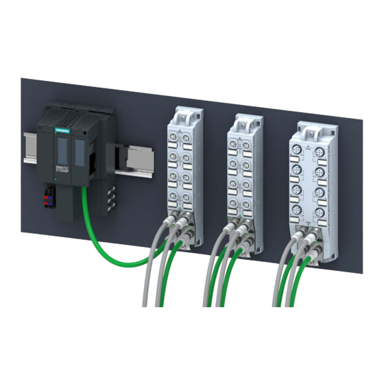
Application planning Mixed configuration ET 200SP and ET 200AL with ET-Connection You have the option of integrating the I/O modules of the ET 200AL distributed I/O system (IP65/IP67) in a configuration of the ET 200SP distributed I/O system (IP20). The figure below shows a combination of the modules of the ET 200AL and ET 200SP distributed I/O system. - Page 19 Application planning Requirement The following components support mixed configuration: • Interface module – IM 155-6 PN HF (V3.0 or higher) – IM 155-6 PN/2 HF – IM 155-6 PN/3 HF – IM 155-6 PN ST (V3.1 or higher) – IM 155-6 DP HF (V3.0 or higher) –...
- Page 20 Application planning Rules You must observe the following rules when assembling a mixed configuration: • The bus length of the ET 200SP distributed I/O system must not exceed 1 m (without interface module, including BU-Send/BA-Send 1xFC and server module) • A maximum of 16 ET 200AL I/O modules can be connected to ET-Connection •...
- Page 21 Application planning Note Insertion of theBusAdapter BA-Send 1xFC during operation leads to a restart of the interface module. Mixed configuration Equipment Manual, 11/2020, A5E33344611-AD...
-
Page 22: Mounting
Mounting Introduction For the connection of the ET 200AL I/O module via ET-Connection to the ET 200SP, you require the BaseUnit BU-Send with the BusAdapter BA-Send 1xFC. Requirement • The mounting rail is mounted. • The interface module is mounted. Required tools 3 to 3.5 mm screwdriver (only for dismantling the BusAdapter) Mounting BaseUnit BU-Send... -
Page 23: Connecting
Connecting Connecting BaseUnit BU-Send Pin assignment The BaseUnit BU-Send only has one slot for an expansion module. No other connections are available. Schematic circuit diagram ① Backplane bus ② BA-Send 1xFC expansion module Figure 6-1 Schematic circuit diagram BU-Send Mixed configuration Equipment Manual, 11/2020, A5E33344611-AD... - Page 24 Connecting 6.1 Connecting BaseUnit BU-Send Introduction You connect the ET 200AL I/O modules via the BusAdapter BA-Send 1xFC via ET-Connection. ① BusAdapter BA-Send 1xFC ② Connection element for ET-Connection bus cable Figure 6-2 BusAdapter BA-Send 1xFC Required tools Screwdriver with 3 to 3.5 mm blade Required accessories Use the bus cable for ET-Connection as connecting cable between the BusAdapter BA-Send 1xFC and the ET 200AL I/O modules.
- Page 25 Connecting 6.1 Connecting BaseUnit BU-Send Procedure To connect the BusAdapter BA-Send 1xFC , follow these steps: 1. Strip the sheath of the bus cable at the open end as follows: Figure 6-3 Connecting cable Use the Stripping Tool for ET-Connection to do this. The relevant settings are shown on the tool.
- Page 26 Connecting 6.1 Connecting BaseUnit BU-Send 6. Insert and fasten the BusAdapter BA-Send 1xFC with the BaseUnit BU-Send (1 screw with tightening torque of 0.2 Nm). To do this, use a screwdriver with a 3 to 3.5 mm blade. 7. Connect the M8 connector of the bus cable to the first ET 200AL I/O module (socket X30 ET-Connection IN).
- Page 27 Connecting 6.1 Connecting BaseUnit BU-Send BusAdapter BA-Send 1xFC mounted ① BusAdapter BA-Send 1xFC ② Bus cable for ET-Connection Figure 6-5 BusAdapter BA-Send 1xFC mounted Mixed configuration Equipment Manual, 11/2020, A5E33344611-AD...
-
Page 28: Configuring
Configuring Introduction The mixed configuration allows the connection of up to 16 ET 200AL I/O modules to the ET 200SP via ET-Connection. The figure below shows the configuration of the ET-Connection and the assignment of the slots. ① ET 200SP I/O modules ⑤... - Page 29 Configuring Rules Observe the following rules when configuring: • With mixed configurations, the following maximum configuration is possible: – 31 slots for ET 200SP modules (IM 155-6 DP HF and IM 155-6 PN ST) – 63 slots for ET 200SP modules (IM 155-6 PN HF and CPUs) –...
- Page 30 Configuring Configuration example An example of a mixed configuration is shown below: Hardware configuration ① ET 200SP I/O modules ⑥ 2nd ET 200AL I/O module ② ET 200SP server module ⑦ 3rd ET 200AL I/O module ③ Slots ⑧ 4th ET 200AL I/O module ④...
-
Page 31: Technical Specifications
Technical specifications Technical specifications BaseUnit BU-Send Technical specifications of the BaseUnit BU-Send Article number 6ES7193-6BN00-0NE0 General information HW functional status from FS04 Ambient conditions Ambient temperature during operation -30 °C • horizontal installation, min. 60 °C • horizontal installation, max. -30 °C •... -
Page 32: Technical Specifications Busadapter Ba-Send 1Xfc
Technical specifications 8.2 Technical specifications BusAdapter BA-Send 1xFC Technical specifications BusAdapter BA-Send 1xFC Technical specifications of the BusAdapter BA-Send 1xFC Article number 6ES7193-6AS00-0AA0 General information Product type designation BA-Send 1xFC HW functional status From FS05 Interfaces Supports protocol for PROFINET IO Cable length 15 m;...
Need help?
Do you have a question about the Simatic ET 200SP and is the answer not in the manual?
Questions and answers