Siemens SIMATIC ET 200AL System Manual
Distributed i/o system
Hide thumbs
Also See for SIMATIC ET 200AL:
- Compact operating instructions (2349 pages) ,
- System manual (2255 pages) ,
- Manual (86 pages)
Table of Contents
Advertisement
Advertisement
Table of Contents

Subscribe to Our Youtube Channel
Related Manuals for Siemens SIMATIC ET 200AL


Summary of Contents for Siemens SIMATIC ET 200AL
- Page 1 Distributed I/O system...
- Page 2 Preface System overview SIMATIC Documentation guide Application planning ET 200AL Distributed I/O system Mounting Connecting System Manual Configuring Configuration control (option handling) Commissioning Maintenance Technical specifications Safety-related shutdown of ET200AL standard modules Dimension drawings Accessories/spare parts 08/2019 A5E31861578-AG...
- Page 3 Note the following: WARNING Siemens products may only be used for the applications described in the catalog and in the relevant technical documentation. If products and components from other manufacturers are used, these must be recommended or approved by Siemens. Proper transport, storage, installation, assembly, commissioning, operation and maintenance are required to ensure that the products operate safely and without any problems.
-
Page 4: Preface
Basic knowledge required A basic knowledge of automation technology is required to understand the documentation. Validity of the documentation This documentation is valid for SIMATIC ET 200AL distributed I/O system. Conventions Please observe notes labeled as follows: Note A note contains important information on the product described in the documentation and on the handling of the product to which particular attention should be paid. - Page 5 Siemens' products and solutions undergo continuous development to make them more secure. Siemens strongly recommends that product updates are applied as soon as they are available and that the latest product versions are used. Use of product versions that are no longer supported, and failure to apply the latest updates may increase customers' exposure to cyber threats.
- Page 6 This information is provided by the Siemens Industry Online Support in the Internet (http://www.siemens.com/automation/service&support). Industry Mall The Industry Mall is the catalog and order system of Siemens AG for automation and drive solutions on the basis of Totally Integrated Automation (TIA) and Totally Integrated Power (TIP).
-
Page 7: Table Of Contents
Table of contents Preface ..............................3 System overview ............................. 8 What is the SIMATIC ET 200AL distributed I/O system? ............8 Components ........................... 11 Documentation guide ..........................12 Application planning ..........................14 Hardware configuration ......................14 Configuration variants with ET-Connection ................15 3.2.1... - Page 8 Table of contents Transferring the control data record in the user program of the CPU ........62 Behavior during operation ....................... 64 Commissioning ............................. 65 PROFINET IO ......................... 65 8.1.1 Commissioning ET 200AL on PROFINET IO ................. 65 8.1.2 Startup on PROFINET IO ....................... 66 8.1.3 PROFIenergy ..........................
-
Page 9: System Overview
What is the SIMATIC ET 200AL distributed I/O system? SIMATIC ET 200AL The SIMATIC ET 200AL distributed I/O system is a scalable and highly flexible, distributed I/O system for connecting process signals to a higher-level control system with a field bus. - Page 10 1.1 What is the SIMATIC ET 200AL distributed I/O system? Area of application The SIMATIC ET 200AL distributed I/O system is especially well suited for use in tight spaces, moving applications and for assembly and handling technology. Thanks to its scalable construction, you have the option to precisely customize its configuration to your on site needs.
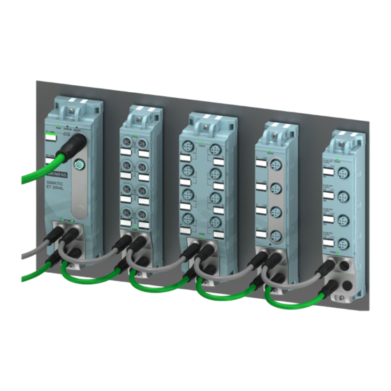
- Page 11 System overview 1.1 What is the SIMATIC ET 200AL distributed I/O system? Configuration example The figure below shows a configuration example of the SIMATIC ET 200AL distributed I/O system with a PROFINET interface module. ① Interface module (PROFINET) ② Digital input/Digital output module ③...
-
Page 12: Components
System overview 1.2 Components Components Components of the ET 200AL distributed I/O system The following table shows and explains the function of the most important components of the ET 200AL distributed I/O system. Table 1- 1 Components of the ET 200AL distributed I/O system Components Function View... -
Page 13: Documentation Guide
Documentation guide The documentation for the SIMATIC ET 200AL distributed I/O system is arranged into three areas. This arrangement enables you to access the specific content you require. Basic information The System Manual and Getting Started describe in detail the configuration, installation, wiring and commissioning of the SIMATIC ET 200AL distributed I/O system. - Page 14 You must register once to use the full functionality of "mySupport". You can find "mySupport" on the Internet (https://support.industry.siemens.com/My/ww/en). Application examples The application examples support you with various tools and examples for solving your automation tasks.
-
Page 15: Application Planning
Application planning Hardware configuration Mechanical maximum configuration The following tables show the rules of the mechanical configuration. As soon as one of the following rules applies, the maximum configuration has been reached. Table 3- 1 Maximum mechanical configuration - on ET 200AL interface module Properties Rule (max.) Interface modules... -
Page 16: Configuration Variants With Et-Connection
Application planning 3.2 Configuration variants with ET-Connection Electrical maximum configuration The number of usable I/O modules of a potential group is limited by the following points: ● Power requirements of the I/O modules ● Power requirements of the components supplied via these I/O modules The maximum infeed current of the I/O modules is 4 A with 1L+ supply voltage (non- switched) and 2L+ load voltage (switched). - Page 17 Application planning 3.2 Configuration variants with ET-Connection ET-Connection1 and ET-Connection2 The figure below shows a configuration in the IP65/IP67 environment with two ET-Connection lines Figure 3-2 ET 200AL with ET-Connection1 and ET-Connection2 Distributed I/O system System Manual, 08/2019, A5E31861578-AG...
-
Page 18: Hybrid Configuration Et 200Al/Et 200Sp With Et-Connection
Application planning 3.2 Configuration variants with ET-Connection 3.2.2 Hybrid configuration ET 200AL/ET 200SP with ET-Connection Hybrid configuration ET 200AL and ET 200SP You have the option to integrate the I/O modules of the ET 200AL distributed I/O system (IP65/IP67) in a configuration of the ET 200SP distributed I/O system (IP20). The figure below shows a combination of the modules of the ET 200AL and ET 200SP distributed I/O systems. - Page 19 Application planning 3.2 Configuration variants with ET-Connection Requirement For a hybrid configuration, you need at least the following components: ● Interface module – IM 155-6 PN HF (V3.0 or higher) – IM 155-6 PN/2 HF (V4.2 or higher) – IM 155-6 PN/3 HF (V4.2 or higher) –...
- Page 20 Application planning 3.2 Configuration variants with ET-Connection Procedure Watch video sequence (https://support.industry.siemens.com/cs/ww/en/view/95886672) Proceed as follows to put together a multi-tier configuration: 1. Mount the BaseUnit BU-Send directly to the right of the ET 200SP interface module or the ET 200SP CPU.
-
Page 21: Mounting
Mounting Basics Introduction All the modules of the ET 200AL distributed I/O system are designed for the degree of protection IP65/IP67. This means that you can directly mount this system in your plant. Installation position You can mount the ET 200AL distributed I/O system in any position. Minimum clearances At ambient temperatures of 50 °C or higher, please ensure that the module is mounted at a distance of least 1 cm from an adjacent module or another device. -
Page 22: Mounting Modules
Mounting 4.2 Mounting modules Mounting modules Introduction The modules of the ET 200AL distributed I/O system are designed for installation on a level, firm surface. Thanks to the axisymmetrical drill holes in the modules, you have the option to fasten the modules on an aluminum profile using tee nuts. - Page 23 ● The distance between the top and bottom drill hole is identical for all modules. Mounting interface module and 45 mm I/O modules (front) Watch video sequence (https://support.industry.siemens.com/cs/ww/en/view/95886672) The interface modules and the 45 mm I/O modules have an attachment point on top and on the bottom.
- Page 24 4.2 Mounting modules Mounting 30 mm I/O modules (front or side) Watch video sequence (https://support.industry.siemens.com/cs/ww/en/view/95886672) The 30 mm I/O modules have an attachment point on top and on the bottom. You also have the option of fastening the 30 mm I/O modules at the side. When fastening them at the side, you must use the supplied spacers.
- Page 25 Mounting 4.2 Mounting modules Fastening for cable ties All module of the ET 200AL distributed I/O system have an integrated attachment point for cable ties. The attachment points are found on all four corners of the modules. The figure below shows the top left attachment point for 2.5 mm wide cable ties for fastening the cables.
-
Page 26: Connecting
Connecting Rules and regulations for operation Introduction Depending on the area of application, the ET 200AL distributed I/O system, as a component of plants and systems, requires that special rules and specifications be followed. This section gives an overview of the most important rules to be followed for integration of the ET 200AL distributed I/O system in a plant or in a system. - Page 27 If there is a danger due to overvoltages, you must take lightning protection measures for internal lightning protection (e.g. lightning protection elements. You will find additional information in the Designing interference-free controllers (https://support.industry.siemens.com/cs/ww/en/view/59193566) function manual). ● For 24 V DC supply: Ensure that there is a safe (electrical) separation of low voltage (SELV/PELV) according to IEC 61010-2-201 or IEC 60950-1.
-
Page 28: Operation Of The Et 200Al On Grounded/Non-Grounded Infeed
Connecting 5.2 Operation of the ET 200AL on grounded/non-grounded infeed Operation of the ET 200AL on grounded/non-grounded infeed Introduction Information is provided below on the overall configuration of an ET 200AL distributed I/O system on a grounded incoming supply (TN-S network). The specific subjects discussed are: ●... - Page 29 Connecting 5.2 Operation of the ET 200AL on grounded/non-grounded infeed ET 200AL in the overall configuration The figure below shows the ET 200AL distributed I/O system in the complete electrical configuration using the example of an interface module. ① Main switch ②...
- Page 30 Connecting 5.2 Operation of the ET 200AL on grounded/non-grounded infeed Components and protective measures Various components and protective measures are stipulated for setting up a complete plant. The types of components and the degree to which the protective measures are mandatory depend on the IEC regulation that applies to your plant setup.
-
Page 31: Electrical Configuration Of The Et 200Al
Connecting 5.3 Electrical configuration of the ET 200AL Electrical configuration of the ET 200AL Electrical isolation When electrically configuring the ET 200AL distributed I/O system, there is electrical isolation between: ● Load voltage 2L+ and all other switching parts ● Communication interfaces (PROFINET/PROFIBUS) of the interface modules and all other switching parts ●... - Page 32 Connecting 5.3 Electrical configuration of the ET 200AL Figure 5-3 Potential conditions of the ET 200AL distributed I/O system (Part 2) Connection of a digital output with a digital input WARNING Pay attention to the potential group When a digital output is connected to a digital input, pay attention to the potential groups. Depending on the configuration, 1M and 2M may then be connected, resulting in elimination of the electrical isolation between 1L+ and 2L+.
- Page 33 Connecting 5.3 Electrical configuration of the ET 200AL Cable protection According to IEC 60364, cable protection is required, i.e. you must always secure the incoming lines externally. You must secure all incoming supply voltages with a UL/IEC approved 24 V DC/4 A fuse (trigger characteristic type B or C).
-
Page 34: Connecting Et 200Al To Functional Earth
Connecting 5.4 Connecting ET 200AL to functional earth Connecting ET 200AL to functional earth Introduction You must connect the distributed I/O system ET 200AL to functional earth (FE) What is functional earth? All ET 200AL modules feature a functional earth connection. This connection is used to suppress interference sensitivity, but not for protection purposes. -
Page 35: Mounting Et 200Al Modules On Non-Conductive Substrate
Connecting 5.4 Connecting ET 200AL to functional earth Mounting To connect modules of the ET 200AL distributed I/O system to functional earth with a conductive mounting substrate, proceed as follows: 1. Drill two fastening holes. 2. Screw the module with the M4 fastening screws using a torque of 1.2 Nm. Note Earthing with conductive mounting substrate When you fasten a module of the ET 200AL distributed I/O system on a conductive,... - Page 36 Connecting 5.4 Connecting ET 200AL to functional earth Mounting To connect modules of the ET 200AL distributed I/O system to functional earth, proceed as follows: 1. Drill two fastening holes. 2. Strip the grounding cable. 3. Fasten the cable lug to the grounding cable. 4.
-
Page 37: Connecting Cables For Et 200Al
Connecting 5.5 Connecting cables for ET 200AL Connecting cables for ET 200AL Impact of cable length on the supply voltage When wiring your configuration, you must take into account the impact of the cable length on the supply voltage of the ET 200AL distributed I/O system. CAUTION Pay attention to maximum incoming currents For each power supply (1L+, 2L+), you can feed in a maximum of 4A. -
Page 38: Wiring
Connecting 5.6 Wiring Wiring Connection Connect all cables to the front side of the modules: ● Supply voltage and ET-Connection to the 4-pole M8 round sockets and M8 round connectors ● Signal lines to the 3-pole M8 or 4/5-pole M12 round sockets ●... - Page 39 Connecting 5.6 Wiring Accessories required for the connection of ET-Connection You need the following accessories: ● ET-Connection cables ● 4-pole M8 connection plug Note ET-Connection cables When connecting ET-Connection use only the offered cables. Connecting M8 connectors To connect M8 connectors, proceed as follows: 1.
- Page 40 Pin assignment of the sockets The pin assignment of the sockets can be found in the manuals for the interface modules (https://support.industry.siemens.com/cs/ww/en/ps/14246/man) and I/O modules (https://support.industry.siemens.com/cs/ww/en/ps/14247/man) in the section on pin assignment and on the side surface of the module. Distributed I/O system...
- Page 41 Connecting 5.6 Wiring Y-cable The Y-cable allows you to connect two actuators or sensors to the inputs or outputs. The use of a Y-cable is particularly recommended when two channels are occupied for each socket of an I/O device. The Y-cable distributes the channels to two circular connectors. The figure below shows the wiring of the Y-cable.
-
Page 42: Et 200Al Marking
Connecting 5.7 ET 200AL marking ET 200AL marking 5.7.1 Factory markings Introduction For better orientation, the ET 200AL distributed I/O system is identified using various markings which will help you when configuring and connecting the modules. Marking of the interfaces The interfaces of the modules are factory-labeled. -
Page 43: Optional Markings
Connecting 5.7 ET 200AL marking 5.7.2 Optional markings Introduction In addition to the factory markings, there are also optional possibilities for labeling and/or identifying interfaces and modules on the ET 200AL distributed I/O system. Identification label The identification labels come with each module as strips and can be machine-printed. A strip has 10 identification labels measuring 10 x 5 mm in the color RAL9016. - Page 44 Connecting 5.7 ET 200AL marking Required tools You need a screwdriver with 3 mm blade width (only to remove identification labels). Mounting procedure To mount an identification label, proceed as follows: 1. Print the identification label using commercially available marking systems. 2.
-
Page 45: Configuring
Configuring Introduction You configure and assign parameters for the ET 200AL distributed I/O system (interface modules and I/O modules) using STEP 7 or the configuration software of another manufacturer. Requirements Table 6- 1 Configuration software and requirements Configuration software Requirements Installation information STEP 7 (TIA Portal) as of V14 STEP 7 online help... - Page 46 PROFINET IO, PROFIBUS DP: • IO modules as of Support Package HSP 0260 STEP 7 (TIA Portal) as of V13 PROFINET IO • Update 3 GSD file: GSDML-Vx.y-Siemens- Software of third-party manufac- ET200AL-"Date in format Manufacturer documen- turer tation yyyymmdd".xml (https://support.industry.siemens.co m/cs/ww/en/view/92346477) for example: GSDML-V2.31-...
- Page 47 Configuring Configuration - PROFINET maximum configuration Each of the connections for ET-Connection occupies a slot in the configuration. The slots for ET-Connection1 and ET-Connection2 are specified statically in the PROFINET GSD file. ET- Connection1 is permanently on slot 1 and ET-Connection2 on slot 18. The fixed slot assignment of ET-Connection1 and ET-Connection2 offers you the following advantages: ●...
- Page 48 Configuring Configuration - PROFIBUS maximum configuration Each of the connections for ET-Connection occupies a slot in the configuration. The slot for ET-Connection1 is statically defined in the PROFIBUS GSD file. ET-Connection1 is always permanently installed in slot 1. Always place the topology module for ET-Connection2 on slot 18.
-
Page 49: Configuration Control (Option Handling)
Configuration control (option handling) Configuration control Introduction With configuration control (option handling), you handle various standard machine configuration levels in one project without having to change the hardware configuration or user program. Operating principle of configuration control You can use configuration control to operate different standard machine configurations with a single configuration of the ET 200AL distributed I/O system. - Page 50 Configuration control (option handling) 7.1 Configuration control The following figure shows 3 configurations of a standard machine with the corresponding station options of the ET 200AL distributed I/O system. Figure 7-1 Various configuration levels of a standard machine with the corresponding station options of the ET 200AL distributed I/O system.
- Page 51 Library for configuration control A library for configuration control is available for download (https://support.industry.siemens.com/cs/ww/en/view/29430270) on the internet. The library contains data types with the structure of the control data records for the ET 200AL distributed I/O system. You can implement your flexible automation solution economically with the help of these data types.
-
Page 52: Configuring
Configuration control (option handling) 7.2 Configuring Configuring Requirements Via PROFINET IO: ● Configuration software, for example STEP 7 Professional as of V13 ● IM 157-1 PN ● You have assigned the interface module to an IO controller in STEP 7 Via PROFIBUS DP: ●... - Page 53 Configuration control (option handling) 7.2 Configuring Required steps Enable the "Allow to reconfigure the device via the user program" parameter when configuring the interface module. ● The parameter "Enable reconfiguration of device via user program" is located in the properties of the interface module under "Module parameters" > "Configuration control". Figure 7-2 Enabling configuration control using the IM 157-1 PN as an example Distributed I/O system...
-
Page 54: Creating The Control Data Record
Configuration control (option handling) 7.3 Creating the control data record Creating the control data record 7.3.1 Introduction Required steps The following description shows as an example how you can create a control data record for the configuration control in STEP 7 (TIA Portal). To create a control data record for the configuration control, follow these steps: 1. - Page 55 Configuration control (option handling) 7.3 Creating the control data record 3. Create an array of the data type of the above created PLC data type in the data block. The following figure shows a data block containing the control data records for an ET200AL interface module.
-
Page 56: Control Data Record For The Et 200Al Distributed I/O System
Configuration control (option handling) 7.3 Creating the control data record Rules Observe the following rules: ● Slot entries in the control data record outside the station master are ignored by the interface module. ● The control data record must contain the entries up to the last slot of the station option. ●... - Page 57 Configuration control (option handling) 7.3 Creating the control data record Control data record For configuration control of the ET 200AL distributed I/O system you define a control data record 196 V2.1, which contains a slot assignment for the modules. The table below shows the structure of a control data record with explanations of the individual elements.
-
Page 58: Feedback Data Record At The Et200Al Distributed I/O System
You have moved the DQ module to Slot 2 in the station option. In order to set up PROFIenergy for this module use Slot 2 in Data record 3. You can find more information about PROFIenergy in the Interface module IM 157-1 PN (https://support.industry.siemens.com/cs/ww/en/view/89254863) Equipment Manual. 7.3.3 Feedback data record at the ET200AL distributed I/O system... - Page 59 Configuration control (option handling) 7.3 Creating the control data record Feedback data record The feedback data record exists only when configuration control is configured and always refers to the maximum configuration limits without interface module, i.e., 34 slots. Partial reading of the feedback data record is possible. Table 7- 3 Feedback data record Byte...
-
Page 60: Example Of A Configuration Control
Configuration control (option handling) 7.3 Creating the control data record Error messages In the case of an error when reading the feedback data record, the RDREC instruction returns the following error messages via the STATUS block parameter: Table 7- 4 Error messages Error code Meaning... - Page 61 Configuration control (option handling) 7.3 Creating the control data record Station option with associated control data record The configuration with the station options 2 and 4 differ from the station master as follows: ● The modules for options 1 and 3 do not exist. Figure 7-6 Example: Hardware configuration of Station option 2 and 4 with the associated control data record in STEP 7...
- Page 62 You can find a detailed application example for the configuration control in S7-1500 in here under the keyword "Application example for ET 200SP (PROFINET) and S7-1500 based on the library" on the Internet (https://support.industry.siemens.com/cs/ww/en/view/29430270). Distributed I/O system System Manual, 08/2019, A5E31861578-AG...
-
Page 63: Transferring The Control Data Record In The User Program Of The Cpu
Configuration control (option handling) 7.4 Transferring the control data record in the user program of the CPU Transferring the control data record in the user program of the CPU Required steps Transfer the created control data record 196 to the interface module using the WRREC (Write data record) instruction. - Page 64 Configuration control (option handling) 7.4 Transferring the control data record in the user program of the CPU Error messages In case of error, the WRREC instruction returns the following error messages via the STATUS block parameter: Table 7- 5 Error messages Error code Meaning 80B1...
-
Page 65: Behavior During Operation
Configuration control (option handling) 7.5 Behavior during operation Behavior during operation Effect of discrepancy between station master and station option For the online display and for the display in the diagnostics buffer (module OK or module faulty), the station master is always used and not the differing station option. Example: A module outputs diagnostics data. -
Page 66: Commissioning
ET 200AL interface module automatically switches to RUN mode Reference You can find additional information on assigning the PROFINET IO parameters in the PROFINET with STEP 7 V14 (https://support.industry.siemens.com/cs/ww/en/view/49948856) function manual. Distributed I/O system System Manual, 08/2019, A5E31861578-AG... -
Page 67: Startup On Profinet Io
Commissioning 8.1 PROFINET IO 8.1.2 Startup on PROFINET IO Principle of operation The figure below schematically shows the startup of the ET 200AL distributed I/O system on the PROFINET IO (= IO device) as a flow chart. Figure 8-1 Startup of the ET 200AL distributed I/O system on the PROFINET IO Distributed I/O system System Manual, 08/2019, A5E31861578-AG... -
Page 68: Profienergy
Commissioning 8.1 PROFINET IO The figure below schematically shows the startup of an ET 200AL I/O module after an ET 200AL PROFINET interface module. Figure 8-2 Startup of the ET 200AL I/O module 8.1.3 PROFIenergy PROFIenergy (for PROFINET) makes it possible to reduce the energy consumption of the device using the PROFIenergy command during production downtime. - Page 69 Application Profile PROFIenergy; Technical Specification for PROFINET; as well as in the following documentation: ● IM 157-1 PN interface module (https://support.industry.siemens.com/cs/ww/en/view/89254863) manual ● I/O modules (https://support.industry.siemens.com/cs/ww/en/ps/14247/man) manuals ● PROFINET System Description (https://support.industry.siemens.com/cs/ww/en/view/19292127) system manual ● PROFINET with STEP 7 V14 (https://support.industry.siemens.com/cs/ww/en/view/49948856), function manual,...
-
Page 70: Profibus Dp
Mounting the ET 200AL interface module Section Mounting (Page 20) Setting the PROFIBUS DP address on the IM 157-1 DP interface module ET 200AL PROFIBUS interface module (https://support.industry.siemens.com/cs/ww /en/view/89255073) manual, section Setting the PROFIBUS DP address and terminating resistor Wiring the ET 200AL interface module... -
Page 71: Startup On Profibus Dp
Commissioning 8.2 PROFIBUS DP 8.2.2 Startup on PROFIBUS DP Principle of operation The figure below schematically shows the startup of the ET 200AL distributed I/O system on the PROFIBUS DP (= DP slave) as a flow chart. Figure 8-3 Startup of the ET 200AL distributed I/O system on PROFIBUS DP Distributed I/O system System Manual, 08/2019, A5E31861578-AG... - Page 72 Commissioning 8.2 PROFIBUS DP The figure below schematically shows the startup of an ET 200AL I/O module after an ET 200AL PROFIBUS interface module as flow chart. Figure 8-4 Startup of an ET 200AL I/O module Distributed I/O system System Manual, 08/2019, A5E31861578-AG...
-
Page 73: Identification And Maintenance Data
Commissioning 8.3 Identification and maintenance data Identification and maintenance data 8.3.1 Reading out and entering I&M data Introduction Identification data I&M is information that is saved either as read-only (I data) or read/write (M data) on the interface module. Identification data (I&M0): Manufacturer information on the module that is read-only and in some cases is also printed on the module housing, for example, article number, serial number and firmware version. - Page 74 During the loading of the hardware configuration, the I&M data are also loaded. Reference You can find additional information on I&M data of the ET 200SP (mixed configuration) in the ET 200SP distributed I/O system (https://support.industry.siemens.com/cs/ww/en/view/58649293) system manual. Distributed I/O system System Manual, 08/2019, A5E31861578-AG...
-
Page 75: Data Record Structure For I&M Data
Commissioning 8.3 Identification and maintenance data 8.3.2 Data record structure for I&M data Reading I&M data records (distributed via PROFINET IO) You can directly access specific identification data by selecting Read data record ("RDREC" instruction). You obtain the corresponding part of the identification data under the associated data record index. - Page 76 Explanation Identification data 0: (data record index AFF0 hex) VendorIDHigh read (1 byte) This is where the name of the manufac- turer is stored (42 = SIEMENS AG). VendorIDLow read (1 byte) Order_ID read (20 bytes) 6ES7157-1AB00-0AB0 Order number of the module (e.g. of...
-
Page 77: Maintenance
Maintenance Replacing modules Replacing modules Replacing a module is not permitted during ongoing operation. WARNING Material damage can occur If you remove/insert modules with the power connected, this can lead to undefined states in your system. Material damage to the ET 200AL distributed I/O system may occur as a result. Only remove or replace modules when the power is disconnected. - Page 78 Maintenance 9.1 Replacing modules 4. Replace the module. Note "New" module The removed module may only be replaced by a module of the same type. 5. Fasten the module with a torque of 1.2 Nm. 6. Connect all cables. 7. Turn the supply voltage on. WARNING Pay attention to the slot number of the module If you mix up the ET 200AL I/O modules when connecting them, this can cause personal...
-
Page 79: Firmware Update
● Online with STEP 7, TIA Portal V13 or higher Reference You can find additional information on the procedure in the FAQs on the Internet (https://support.industry.siemens.com/cs/ww/en/view/88778936) and in the online help for STEP 7. Distributed I/O system System Manual, 08/2019, A5E31861578-AG... -
Page 80: Resetting Interface Module To Factory Settings (Profinet)
Maintenance 9.3 Resetting interface module to factory settings (PROFINET) Resetting interface module to factory settings (PROFINET) Introduction When you "Reset to factory settings", the interface module is reset to the delivery state settings. This means that all information that was saved internally on the interface module is deleted. -
Page 81: Cleaning Modules
Maintenance 9.4 Cleaning modules Requirement You need an online connection to reset an interface module to factory settings. Procedure with STEP 7 (TIA Portal) Connect the PG/PC to the PROFINET IO interface of the ET 200AL distributed I/O system. Make sure that there is an online connection to the interface module which is to be reset to factory settings. -
Page 82: Technical Specifications
Reference The certificates for the markings and approvals can be found on the Internet (https://support.industry.siemens.com). 10.1 Standards and authorizations Currently valid markings and authorizations... - Page 83 ● 2014/30/EU "Electromagnetic Compatibility" (EMC directive) ● 2011/65/EU "Restriction of the use of certain hazardous substances in electrical and electronic equipment" (RoHS Directive) The EC declarations of conformity are available to the responsible authorities at: Siemens AG Digital Factory Factory Automation DI FA AS SYS...
- Page 84 Technical specifications 10.1 Standards and authorizations IEC 61131-2 The ET 200AL distributed I/O system meets the requirements and criteria of standard IEC 61131-2, excluding the requirements mentioned in section 11 to 14 (programmable logic controllers, part 2: Equipment requirements and tests). IEC 61010-2-201 The ET 200AL distributed I/O system fulfills the requirements and criteria of standard IEC 61010-2-201.
- Page 85 ET 200AL distributed I/O system in residential areas, radio and TV reception may be affected. Reference The certificates for the markings and approvals can be found on the Internet under Service&Support (http://www.siemens.com/automation/service&support). Distributed I/O system System Manual, 08/2019, A5E31861578-AG...
-
Page 86: Electromagnetic Compatibility
Technical specifications 10.2 Electromagnetic compatibility 10.2 Electromagnetic compatibility Definition Electromagnetic compatibility is the ability of an electrical apparatus to function in a satisfactory manner in its electromagnetic environment without affecting this environment. An I/O device of the ET 200AL distributed I/O system fulfills the requirements of the EMC law of the European Union. - Page 87 Technical specifications 10.2 Electromagnetic compatibility Sinusoidal disturbance variables The following tables show the electromagnetic compatibility of the distributed I/O systems to sinusoidal disturbance variables. Table 10- 2 RF radiation RF radiation according to IEC 61000-4-3 Corresponds to de- Electromagnetic RF field, amplitude modulated gree of severity 80 MHz to 1000 MHz 10 V/m...
-
Page 88: Transport And Storage Conditions
Technical specifications 10.3 Transport and storage conditions 10.3 Transport and storage conditions Transport and storage conditions The modules of the ET 200AL distributed I/O system exceed the specifications regarding transport and storage conditions pursuant to IEC 61131-2. The following table shows the conditions that apply to modules transported or stored in their original packaging. -
Page 89: Mechanical And Climatic Ambient Conditions
Technical specifications 10.4 Mechanical and climatic ambient conditions 10.4 Mechanical and climatic ambient conditions Operating conditions The ET 200AL distributed I/O system is suitable for use in weather-proof, fixed locations. The conditions of use exceed the requirements pursuant to IEC 60721-3-3: ●... - Page 90 Technical specifications 10.4 Mechanical and climatic ambient conditions Climatic ambient conditions The following table shows the type and scope of the tests on climatic ambient conditions. Table 10- 9 Climatic ambient conditions Ambient conditions Fields of application Comments Temperature -25 °C to 55 °C All installation positions Temperature variation 10 K/h...
-
Page 91: 10.5 Details On Insulation, Protection Class, Degree Of Protection And Rated Voltage
Technical specifications 10.5 Details on insulation, protection class, degree of protection and rated voltage 10.5 Details on insulation, protection class, degree of protection and rated voltage Insulation The insulation is designed in compliance with the requirements of IEC 61010-2-201. Note Galvanic isolation with 707 V DC (Type Test) is tested for modules with 24 V DC supply voltage (SELV/PELV). -
Page 92: Safety-Related Symbols For Ip65/Ip67 Modules
Technical specifications 10.6 Safety-related symbols for IP65/IP67 modules 10.6 Safety-related symbols for IP65/IP67 modules The following table contains an explanation of the symbols located on your IP65/67 modules, their packaging or in the accompanying documentation. Symbol Meaning General warning sign Caution/Notice You must read the product documentation. -
Page 93: Safety-Related Shutdown Of Et200Al Standard Modules
Safety-related shutdown of ET200AL standard modules Introduction The diagram below illustrates the fail-safe shutdown of ET 200AL standard modules. In the configuration shown in the diagram below, all digital outputs that are operated with the 2L+ and 2M supply of the ET 200AL standard modules are switched to the safe OFF state. This step achieves the safety class SIL2/category 3/PLd. - Page 94 Siemens AG Digital Factory DI FA AS SYS Postfach 1963 D-92209 Amberg Reference You can find additional information as well as an overview of the modules with safety-related shutdown on the Internet (https://support.industry.siemens.com/cs/us/en/view/39198632). Distributed I/O system System Manual, 08/2019, A5E31861578-AG...
-
Page 95: Dimension Drawings
40 mm to 46 mm. Detailed information on the dimensions of the individual modules can be found in the manuals for the Interface modules (https://support.industry.siemens.com/cs/ww/en/ps/14246/man) and I/O modules (https://support.industry.siemens.com/cs/ww/en/ps/14247/man) in the section "Dimension drawing". Figure B-1 Module dimension drawings (front view) -
Page 96: Accessories/Spare Parts
Accessories/spare parts Accessories/spare parts Accessories for the ET 200AL distributed I/O system Table C- 1 Accessories for ET-Connection Designation Length Article number Cable Standard Bus cable for ET-Connection M8, pre-assembled on 0.19 m 6ES7194-2LH02-0AA0 6ES7194-2MH02-0AA0 both sides with 2 x M8 connectors, 4-pole, shielded 0.3 m 6ES7194-2LH03-0AA0 6ES7194-2MH03-0AA0... - Page 97 Accessories/spare parts C.1 Accessories/spare parts Table C- 2 Accessories for power supply Designation Length Article number Cable Standard Power cable M8, pre-assembled on both sides with 0.19 m 6ES7194-2LH02-1AA0 6ES7194-2MH02-1AA0 M8 connector and M8 socket, 4-pole 0.3 m 6ES7194-2LH03-1AA0 6ES7194-2MH03-1AA0 1.0 m 6ES7194-2LH10-1AA0 6ES7194-2MH10-1AA0...
- Page 98 Accessories/spare parts C.1 Accessories/spare parts Table C- 3 M12 connector Designation Article number Non-preassembled connectors for X1 DP1 (pin) PROFIBUS M12 plug connector 180° with female insert 6GK1905-0EB00 PROFIBUS M12 plug connector FastConnect 180° with female insert 6GK1905-0EB10 PROFIBUS M12 plug connector, angled with female insert 3RK1902-1DA00 Non-preassembled connectors for X1 DP2 (socket) PROFIBUS M12 plug connector 180°...
- Page 99 Accessories/spare parts C.1 Accessories/spare parts Table C- 5 Pre-assembled cable M12 Designation Article number Pre-assembled cable for X1 DP1 and X1 DP2 PROFIBUS M12 connecting cable, trailing cable, pre-assembled on both sides 0.3 m 6XV1830-3DE30 with PROFIBUS M12 connectors, 180° (one end with socket, one end with pin) 0.5 m 6XV1830-3DE50 1.0 m...
-
Page 100: Cables
6GK1905-6AA00 Online catalog Other article numbers for the ET 200AL distributed I/O system can be found on the Internet (https://mall.industry.siemens.com) in the online catalog and the online order system. Cables Cables for ET-Connection standard and PUR cable The cables for ET-Connection are available in the following versions and lengths: ●... - Page 101 Accessories/spare parts C.2 Cables The following table shows the technical properties of the bus cable ET-Connection standard. Table C- 8 Cables for ET-Connection General information Product type designation BUS CABLE ET-CONNECTION Function To connect ET-CONNECTION devices with de- gree of protection IP65/IP67 Degree of protection and protection class IP65 IP67...
- Page 102 Accessories/spare parts C.2 Cables The following table shows the technical properties of the bus cable ET-Connection, PUR cable. Table C- 9 Cables for ET-Connection, PUR cable General information Product type designation BUS CABLE ET-CONNECTION, PUR CABLE Function To connect ET-CONNECTION devices with de- gree of protection IP65/IP67 Degree of protection and protection class IP65...
- Page 103 Accessories/spare parts C.2 Cables Connecting cable for ET-Connection standard and PUR cable You can use the connecting cable between two cables for ET-Connection. Typical applications for using connecting cable for ET-Connection are: ● Combination of individual cable lengths by joining multiple pre-assembled cables for ET-Connection.
- Page 104 Accessories/spare parts C.2 Cables The following table shows the technical properties of the connecting cable for ET-Connection standard. Table C- 10 Connecting cables for ET-Connection General information Product type designation CONNECTING CABLE FOR BUS CABLE ET- CONNECTION, CABLE 0.2 M Function To connect two bus cables ET-CONNECTION Degree of protection and protection class...
- Page 105 Accessories/spare parts C.2 Cables The following table shows the technical properties of the connecting cable for ET-Connection, PUR cable. Table C- 11 Connecting cables for ET-Connection, PUR cable General information Product type designation CONNECTING CABLE FOR BUS CABLE ET- CONNECTION, PUR CABLE 0.2 M Function To connect two bus cables ET-CONNECTION Degree of protection and protection class...
- Page 106 Accessories/spare parts C.2 Cables Cables of power supply standard and PUR cable The cables for the power supply are available in the following versions and lengths: ● Power cable (4-wire), pre-assembled on both sides with a 4-pole M8 pin connector/socket connector –...
- Page 107 Accessories/spare parts C.2 Cables General information Color of the wire insulation of the power wires White, brown, blue black Weight per length 44 kg/km Mechanics/material Type of cable outlet 180° cable outlet 90° cable outlet (with angled connectors) Number of connectors 1 or 2 Connector housing material Plastic...
- Page 108 Accessories/spare parts C.2 Cables General information Color of the cable sheath Gray Color of the wire insulation of the power wires White, brown, blue black Weight per length 44 kg/km Mechanics/material Type of cable outlet 180° cable outlet 90° cable outlet (with angled connectors) Number of connectors 1 or 2 Connector housing material...
-
Page 109: Pin Assignment And Core Color
Accessories/spare parts C.3 Pin assignment and core color Pin assignment and core color Pin assignment of the sockets for ET-Connection The tables below shows the pin assignments of the 2 sockets for the connection of ET-Connection. Table C- 14 Pin assignment for ET-Connection (interface modules) Assignment Assignment of the Front view of the sockets... - Page 110 Accessories/spare parts C.3 Pin assignment and core color Pin assignment of the connector for infeed of the supply voltage The table below shows the pin assignment for infeed of the supply voltage. Table C- 16 Pin assignment of the supply voltage connector Assignment Assignment of the Front view of the...
-
Page 111: Glossary
Glossary A common transfer route to which all devices are connected; it has two defined ends. Configuration Systematic arrangement of individual modules (design). Connection plug Physical connection between device and cable. Device Device that can send, receive or amplify data via the bus, e.g. IO device via PROFINET IO. Diagnostics Monitoring functions for the detection, localization, classification, display, and further evaluation of errors, faults, and alarms. - Page 112 Glossary Ground Conductive earth whose electrical potential can be set equal to zero at any point. All interconnected, inactive parts of a piece of equipment that cannot accept any dangerous contact voltage, even in the event of a fault. Ground Conductive earth whose electrical potential can be set equal to zero at any point.
- Page 113 Glossary PROFINET IO controller Device used to address connected I/O devices (e.g. distributed I/O systems). This means that: The IO controller exchanges input and output signals with assigned I/O devices. The IO controller often corresponds with the CPU in which the automation program is running. PROFINET IO device Distributed field device that can be assigned to one or more IO controllers (e.g.
-
Page 114: Index
Index ET-Connection1 and ET-Connection2, 16 Hybrid configuration, 17 Configuring, 44 Connecting 24 V DC supply, 26 Conductive substrate, 34 M12 connectors, 39 M8 connectors, 38 Non-conductive substrate, 35 Accessories, 95 Connecting cables, 36 Ambient conditions Climatic, 89 Mechanical, 88 Application, 25 Degree of protection, 90 Approvals, 81 Dimension drawing... - Page 115 Safe electrical isolation, 27 Line voltage, 26 Safety relay, 92 Screws, 21 SELV, 27 Setup, 9 Shock, 88 M12 connectors, 39 SIMATIC ET 200AL, 8 M8 connectors, 38 Sinusoidal disturbance variables, 86 Maintenance, 76 Slot number, 77 Maintenance data, 72 Sockets, 40 Marking...
- Page 116 Index in industrial environments, 84 in mixed areas, 84 in residential areas, 84 Vibrations, 88 Wires, 25 Distributed I/O system System Manual, 08/2019, A5E31861578-AG...
Need help?
Do you have a question about the SIMATIC ET 200AL and is the answer not in the manual?
Questions and answers