Siemens SIMATIC ET 200AL System Manual
Io-link i/o modules
Hide thumbs
Also See for SIMATIC ET 200AL:
- Compact operating instructions (2349 pages) ,
- System manual (2255 pages) ,
- Manual (86 pages)

Related Manuals for Siemens SIMATIC ET 200AL


Summary of Contents for Siemens SIMATIC ET 200AL
- Page 1 System manual SIMATIC ET 200AL IO-Link I/O modules Edition 10/2020 support.industry.siemens.com...
- Page 2 Preface ET 200AL IO-Link I/O modules Documentation Guide SIMATIC System overview ET 200AL Application planning IO-Link I/O modules Mounting System Manual Connecting Configuring Commissioning Maintenance Technical specifications Dimension drawings Accessories/spare parts 10/2020 A5E48755395-AA...
- Page 3 Note the following: WARNING Siemens products may only be used for the applications described in the catalog and in the relevant technical documentation. If products and components from other manufacturers are used, these must be recommended or approved by Siemens. Proper transport, storage, installation, assembly, commissioning, operation and maintenance are required to ensure that the products operate safely and without any problems.
-
Page 4: Preface
Purpose of the documentation This documentation provides you with important information on how to configure, install, wire and commission the IO-Link I/O modules of the SIMATIC ET 200AL distributed I/O system. Basic knowledge required A basic knowledge of automation technology is required to understand the documentation. - Page 5 Siemens' products and solutions undergo continuous development to make them more secure. Siemens strongly recommends that product updates are applied as soon as they are available and that the latest product versions are used. Use of product versions that are no longer supported, and failure to apply the latest updates may increase customers' exposure to cyber threats.
- Page 6 Preface Industry Mall The Industry Mall is the catalog and order system of Siemens AG for automation and drive solutions on the basis of Totally Integrated Automation (TIA) and Totally Integrated Power (TIP). You can find catalogs for all automation and drive products on the Internet (https://mall.industry.siemens.com) and in the Information and Download Center.
-
Page 7: Table Of Contents
Table of contents Preface ..............................3 ET 200AL IO-Link I/O modules Documentation Guide ................8 System overview ..........................11 System overview ....................... 11 What are ET 200AL IO-Link I/O modules? ................12 Components ........................14 Application planning ........................... 15 Hardware configuration ..................... 15 Configuration of IO-Link I/O modules ................. - Page 8 Table of contents Maintaining/cleaning the modules ..................53 Technical specifications ........................54 Standards and authorizations ..................... 55 Electromagnetic compatibility .................... 58 Transport and storage conditions ..................59 Mechanical and climatic ambient conditions ..............60 Details on insulation, protection class, degree of protection and rated voltage ....61 Safety-related symbols for IP65/IP67 modules ..............
-
Page 9: 200Al Io-Link I/O Modules Documentation Guide
ET 200AL IO-Link I/O modules Documentation Guide The documentation for the SIMATIC ET 200AL IO-Link I/O modules is arranged into three areas. This arrangement enables you to access the specific content you require. Basic information The system manual describes in detail the configuration, installation, wiring and commissioning of the distributed I/O system SIMATIC ET 200AL IO-Link I/O modules. - Page 10 You must register once to use the full functionality of "mySupport". You can find "mySupport" on the Internet (https://support.industry.siemens.com/My/ww/en). "mySupport" - Documentation With "mySupport", your personal workspace, you make the best out of your Industry Online Support.
- Page 11 You can find the TIA Selection Tool on the Internet (https://support.industry.siemens.com/cs/ww/en/view/109767888). PRONETA SIEMENS PRONETA (PROFINET network analysis) allows you to analyze the plant network during commissioning. PRONETA has two core functions: • The topology overview automatically scans the PROFINET and all connected components.
-
Page 12: System Overview
System overview System overview Introduction A continuous communication down to the lowest field level ensures enhanced use of the functions and performance capability of sensors and actuators. Enhanced use of sensors and actuators allows you to operate your machines and plants more productively. No data other than the actual process value can be exchanged via the standard interfaces (digital, analog) used at the sensor/actuator level. -
Page 13: What Are Et 200Al Io-Link I/O Modules
What are ET 200AL IO-Link I/O modules? SIMATIC ET 200AL IO-Link I/O modules SIMATIC ET 200AL IO-Link I/O modules belong to the SIMATIC ET 200AL distributed I/O system. You can operate the IO-Link I/O modules on any IO-Link master with IP20 or IP67 degree of protection. - Page 14 PROFINET IO and ET connection, and the star topology of IO-Link make this easy to implement. Configuration The IO-Link I/O modules of the SIMATIC ET 200AL distributed I/O system are operated on any IO-Link master. A cable with M12 plug-in connection is used for the communication and power supply.
-
Page 15: Components
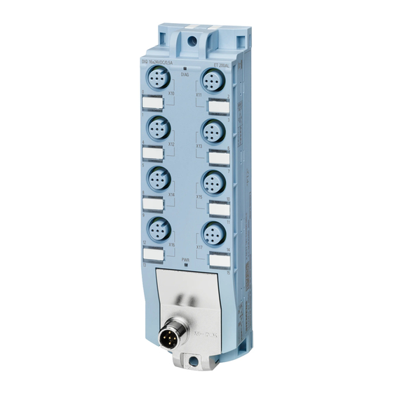
System overview 2.3 Components Components Components of the IO-Link I/O modules The following table shows and explains the function of the components of the IO-Link I/O modules of the ET 200AL distributed I/O system. Table 2- 1 Components of the IO-Link I/O modules Component Function View... -
Page 16: Application Planning
You can find information on the maximum infeed current in the technical specifications of the modules in the respective equipment manuals or on the Internet (https://support.industry.siemens.com/cs/ww/en/view/109742667). Configuration of IO-Link I/O modules Each ET 200AL IO-Link I/O module has an M12 A-coded plug for connection to an IO-Link master. - Page 17 Application planning 3.2 Configuration of IO-Link I/O modules Connection examples The following figure shows a connection example using an S7-1500 IO-Link master with IP20 degree of protection. Figure 3-1 Configuration with IP20 IO-Link master IO-Link I/O modules System Manual, 10/2020, A5E48755395-AA...
- Page 18 Application planning 3.2 Configuration of IO-Link I/O modules The following figure shows a connection example on an ET 200ecoPN IO-Link master with IP65/67 degree of protection. Figure 3-2 Configuration with IP65/67 IO-Link master IO-Link I/O modules System Manual, 10/2020, A5E48755395-AA...
-
Page 19: Mounting
Mounting Basics Introduction The IO-Link I/O modules are designed for IP65/IP67 degree of protection. This means that you can mount the modules directly in your plant. Mounting position You can mount the IO-Link I/O modules in any mounting position. Minimum clearances Maintain a minimum clearance of 2 cm from adjacent modules or other devices when mounting. -
Page 20: Mounting Modules
Mounting 4.2 Mounting modules Mounting modules Introduction The IO-Link I/O modules are designed for mounting on a level, stable surface. Thanks to the axisymmetrical drill holes in the modules, you have the option to fasten the modules on an aluminum profile using tee nuts. The following images shows the aluminum profile on which you can mount the modules. - Page 21 • The distance between the top and bottom drill hole is identical for all modules. Mounting 30 mm wide I/O modules (front or side) Watch video sequence (https://support.industry.siemens.com/cs/ww/en/view/95886672) The 30 mm I/O modules have a fastening point at the top and bottom. The 30 mm wide I/O modules can also be side-fastened.
- Page 22 Mounting 4.2 Mounting modules The figure below shows the dimensions for fastening the 30 mm wide I/O modules using the example of the IO-Link I/O module DIQ 4+DQ 4x24VDC/0.5A 8xM8. Figure 4-2 Dimensions for mounting 30 mm wide I/O modules IO-Link I/O modules System Manual, 10/2020, A5E48755395-AA...
- Page 23 4.2 Mounting modules Mounting 45 mm I/O modules (front mounting) Watch video sequence (https://support.industry.siemens.com/cs/ww/en/view/95886672) The 45 mm wide I/O modules have a fastening point at the top and bottom. Follow the steps below to mount a 45 mm wide I/O module: 1.
- Page 24 Mounting 4.2 Mounting modules Fastening for cable ties All IO-Link I/O modules have integrated fastening points for cable ties. The fastening points are found on all four corners of the modules. The figure below shows the top left fastening point for 2.5 mm cable ties for fastening the cables.
-
Page 25: Connecting
Connecting Rules and regulations for operation Introduction Depending on the area of application, the IO-Link I/O modules, as an integral component of a system, must adhere to special rules. This section gives an overview of the most important rules you must follow when integrating the IO-Link I/O modules in a plant or system. - Page 26 Connecting 5.1 Rules and regulations for operation Line voltage For the line voltage, note the following: • For stationary plants or systems without an all-pole line disconnector, there must be a disconnector unit (all-pole) fitted in the building installation. • For load current supplies, the configured rated voltage range must correspond to the local line voltage.
-
Page 27: 5.2 Operation Of The Io-Link I/O Modules On A Grounded/Ungrounded Infeed
– Line/wire break – Cross-circuit in the cable Reference Additional information can be found in the function manual Designing interference-free controllers (https://support.industry.siemens.com/cs/ww/en/view/59193566). Operation of the IO-Link I/O modules on a grounded/ungrounded infeed Introduction Information on the overall configuration of the IO-Link I/O modules on a grounded infeed (TN-S system) is provided below. - Page 28 Connecting 5.2 Operation of the IO-Link I/O modules on a grounded/ungrounded infeed Supply voltages Provide the IO-Link master with an SELV/PELV 1L+ supply voltage. The SELV/PELV 2L+ load voltage is supplied via the M12-A connector with port class B or via the M12-L power connector.
- Page 29 Connecting 5.2 Operation of the IO-Link I/O modules on a grounded/ungrounded infeed Overall configuration of IO-Link I/O modules The figure below shows the overall electrical configuration using the example of an IO-Link I/O module with port class A on an IO-Link master with port class A. ①...
- Page 30 Connecting 5.2 Operation of the IO-Link I/O modules on a grounded/ungrounded infeed The figure below shows the overall electrical configuration using the example of an IO-Link I/O module with port class A or B on an IO-Link master with port class A. ①...
- Page 31 Connecting 5.2 Operation of the IO-Link I/O modules on a grounded/ungrounded infeed The figure below shows the overall electrical configuration using the example of an IO-Link I/O module with port class B on an IO-Link master with port class B. ①...
- Page 32 Connecting 5.2 Operation of the IO-Link I/O modules on a grounded/ungrounded infeed Components and protective measures Various components and protective measures are stipulated for setting up a complete plant. The types of components and the degree to which the protective measures are mandatory depend on the IEC regulation that applies to your plant setup.
-
Page 33: Electrical Configuration Of The Io-Link I/O Modules
Connecting 5.3 Electrical configuration of the IO-Link I/O modules Electrical configuration of the IO-Link I/O modules Electrical isolation In the electrical configuration of the IO-Link I/O modules, there is electrical isolation between: • IO-Link 1L+: Non-switched supply voltage (electronics/sensor/load supply): Electrically isolated from 2L+ (load voltage supply) •... -
Page 34: Connecting Io-Link I/O Modules To Functional Ground
Connecting 5.4 Connecting IO-Link I/O modules to functional ground Power supply of the configuration Up to two voltage groups are available for the ET 200AL distributed I/O system. • 1L+ via IO-Link (supply voltage / non-switched) • 2L+ via port class B or M12-L power connector (load voltage / switched) Note Connecting and disconnecting of 1L+ IO-Link, 2L+ via port class B or M12-L power connector... -
Page 35: Mounting Io-Link I/O Modules On A Conductive Surface
Connecting 5.4 Connecting IO-Link I/O modules to functional ground 5.4.1 Mounting IO-Link I/O modules on a conductive surface Requirement Conductive surface for mounting of the module Required tool To connect to functional ground, you need the following tool: • Screwdriver or hexagon socket size 3 Required accessories: To connect to functional ground, you need the following accessories: •... -
Page 36: Mounting Io-Link I/O Modules On A Non-Conductive Surface
Connecting 5.4 Connecting IO-Link I/O modules to functional ground 5.4.2 Mounting IO-Link I/O modules on a non-conductive surface Requirement Non-conductive surface for mounting of the module Required tool To connect to functional ground, you need the following tool: • Screwdriver or hexagon socket size 3 •... - Page 37 Connecting 5.4 Connecting IO-Link I/O modules to functional ground The figure below shows how to connect the functional ground. Figure 5-5 Connecting the functional ground Note Grounding in the case of a non-conductive mounting surface Make sure there is a low-impedance connection between the module and functional ground. Reference You will find more information on installing the modules in the section Mounting modules (Page 19).
-
Page 38: Wiring
Connecting 5.5 Wiring Wiring Connection Connect all cables to the front side of the modules: • IO-Link to the 5-pole M12 connector (A-coded) • Signal lines to the 3-pole M8 sockets or 4/5-pole M12 sockets (A-coded) • Additional load voltage to the 5-pole M12 plug (L-coded) Requirement Wire the modules with the supply voltage off. - Page 39 Connecting 5.5 Wiring Connecting M8 connectors To connect M8 connectors, proceed as follows: 1. Insert the plug into the respective round socket on the module. Ensure the correct alignment between plug and socket. 2. Tighten the connector using the knurled screw with a torque of 0.4 Nm. The figure below shows the connection of the M8 plugs, using the example of the IO-Link digital input module DI 8x24VDC 8xM8..
- Page 40 Connecting M12 connectors Pin assignment of the sockets The pin assignment of the sockets can be found in the equipment manuals of the I/O modules (https://support.industry.siemens.com/cs/ww/en/ps/14247/man) in the section on pin assignment and on the side surface of the module. Y-cable The Y-cable allows you to connect two actuators or sensors to the inputs or outputs.
- Page 41 To ensure IP65 or IP67 degree of protection, seal off all unused sockets with sealing caps. Article numbers for accessories/spare parts. You will find the article numbers in the Appendix in section Accessories/spare parts (Page 64). See also Interface modules (https://support.industry.siemens.com/cs/ww/en/ps/14246/man) IO-Link I/O modules System Manual, 10/2020, A5E48755395-AA...
-
Page 42: Marking Of Io-Link I/O Modules
Connecting 5.6 Marking of IO-Link I/O modules Marking of IO-Link I/O modules 5.6.1 Factory markings Introduction For better orientation, the IO-Link I/O modules are furnished with various markings that support you when configuring and connecting the modules. Marking of the interfaces The interfaces of the modules are factory-labeled. -
Page 43: Optional Markings
Connecting 5.6 Marking of IO-Link I/O modules 5.6.2 Optional markings Introduction In addition to the factory markings, there are also optional possibilities for labeling or marking interfaces and modules on the IO-Link I/O modules. Identification label The identification labels come with each IO-Link I/O module as strips and can be machine- printed. -
Page 44: Mounting Identification Labels
Connecting 5.6 Marking of IO-Link I/O modules 5.6.3 Mounting identification labels Introduction This section describes how to mount or remove identification labels. Required tools You need a screwdriver with 3 mm blade width (only to remove identification labels). Mounting procedure To mount an identification label, proceed as follows: 1. -
Page 45: Configuring
The structure of the IODD is identical for all devices from all manufacturers. The structure of the IODD is always represented in the same manner by the IO-Link configuration tools of the master manufacturer (for Siemens, S7-PCT). This ensures that the handling is the same for all IO-Link devices regardless of the manufacturer. - Page 46 This means the IO-Link configuration tool supports the transparent representation of the IO- Link system down to field level. Siemens provides S7-PCT for engineering of the IO-Link system. You can find the relevant device description file, software and function manuals in SIOS.
- Page 47 Configuring 6.2 IODD and Port Configuration Tool - S7-PCT S7-PCT with IODD of an IO-Link I/O module The following figure shows a section from S7-PCT with IODD of an IO-Link I/O module and the device information contained therein. Figure 6-1 S7-PCT with IODD of a device and the device information contained therein IO-Link I/O modules System Manual, 10/2020, A5E48755395-AA...
-
Page 48: Commissioning
Commissioning Startup of the IO-Link I/O module Principle of operation The figure below shows the startup of an IO-Link I/O module on an IO-Link Master schematically as a flow chart. Figure 7-1 Startup of an ET 200AL IO-Link I/O module IO-Link I/O modules System Manual, 10/2020, A5E48755395-AA... -
Page 49: Maintenance
Maintenance Replacing modules Replacing IO-Link I/O modules The replacement of a module is not permitted during ongoing operation. WARNING Property damage can occur If you remove/insert modules while the power is connected, this can lead to undefined states in your system. The IO-Link I/O module may be damaged as a result. - Page 50 Maintenance 8.1 Replacing modules 4. Replace the IO-Link I/O module. Note "New" IO-Link I/O module The removed IO-Link I/O module may only be replaced by a module of the same type. 5. Fasten the IO-Link I/O module with the screws with a torque of 1.2 Nm. 6.
-
Page 51: Firmware Update
Maintenance 8.2 Firmware update Firmware update Introduction During operation, it can become necessary to update the firmware (e.g. for function extensions). You use a firmware update to update the module firmware. Note STOP state during the update When you perform a firmware update for an IO-Link I/O module, the module goes to STOP state during the update. -
Page 52: Resetting A Module
Maintenance 8.3 Resetting a module Resetting a module Introduction With "Restore Factory Setting", the IO-Link I/O module is set to the delivery condition. All information that was saved internally on the IO-Link I/O module is deleted. Options for resetting You can reset the IO-Link I/O module in S7-PCT. You have two different possibilities for this. - Page 53 Maintenance 8.3 Resetting a module Procedure using S7-PCT Connect the PG/PC to the PROFINET IO or PROFIBUS DP interface of the IO-Link master or to your system. Make sure that an online connection to the IO-Link I/O module exists. 1. Select an IO-Link I/O module in the project tree. 2.
-
Page 54: Maintaining/Cleaning The Modules
Maintenance 8.4 Maintaining/cleaning the modules Maintaining/cleaning the modules Maintenance The IO-Link I/O modules are maintenance-free. Note Repairs Repairs to an IO-Link I/O module may only be carried out by the manufacturer. Cleaning When wired, the IO-Link I/O modules comply with degree of protection IP65/IP67 and do not require any cleaning. -
Page 55: Technical Specifications
The technical data of the individual modules can be found in the modules' manuals. If there are discrepancies between the statements in this document and the product manuals, the statements in the product manuals take priority. See also SIOS (https://support.industry.siemens.com) IO-Link I/O modules System Manual, 10/2020, A5E48755395-AA... -
Page 56: Standards And Authorizations
• 2011/65/EU "Restriction of the use of certain hazardous substances in electrical and electronic equipment" (RoHS Directive) The EU Declarations of Conformity are available for the authorities in charge and are kept at the following address: Siemens AG Digital Industries Factory Automation DI FA AS SYS... - Page 57 Technical specifications 9.1 Standards and authorizations Korea Certificate KCC-REM-S49-ET200 Please note that this device corresponds to limit class A with regard to the emission of radio interference. This device can be used in all areas, except residential areas. 이 기기는 업무용(A급) 전자파 적합기기로서 판매자 또는 사용자는 이 점을 주의하시기 바라며 가정...
- Page 58 The ET 200AL IO-Link I/O modules are not intended for use in residential areas. Using the ET 200AL IO-Link I/O modules in residential areas can affect radio and television reception. Reference The certificates for the markings and approvals can be found on the Internet under Service&Support (http://www.siemens.com/automation/service&support). IO-Link I/O modules System Manual, 10/2020, A5E48755395-AA...
-
Page 59: Electromagnetic Compatibility
Technical specifications 9.2 Electromagnetic compatibility Electromagnetic compatibility Definition Electromagnetic compatibility is the ability of an electrical apparatus to function in a satisfactory manner in its electromagnetic environment without affecting this environment. The ET 200AL IO-Link I/O modules fulfill the requirements of the EMC law of the European Single Market. -
Page 60: Transport And Storage Conditions
Technical specifications 9.3 Transport and storage conditions Emission of radio frequency interference The table below shows the interference emission of electromagnetic fields according to EN 55011: limit class A, group 1. Table 9- 4 Interference emission of electromagnetic fields Frequency Interference emission Measuring distance 30 ... -
Page 61: Mechanical And Climatic Ambient Conditions
You can find the values for the operating conditions in the technical specifications of the equipment manuals or on the Internet (https://support.industry.siemens.com/cs/de/en/view/109742718). Tests for mechanical ambient conditions The following table shows the type and scope of the tests for mechanical ambient conditions. -
Page 62: 9.5 Details On Insulation, Protection Class, Degree Of Protection And Rated Voltage
Technical specifications 9.5 Details on insulation, protection class, degree of protection and rated voltage Details on insulation, protection class, degree of protection and rated voltage Insulation The insulation is designed in compliance with the requirements of IEC 61010-2-201. Note For modules with 24 V DC supply voltage (SELV/PELV), electrical isolations are tested with 707 V DC (type test). -
Page 63: Safety-Related Symbols For Ip65/Ip67 Modules
Technical specifications 9.6 Safety-related symbols for IP65/IP67 modules Safety-related symbols for IP65/IP67 modules The following table contains an explanation of the symbols located on your IP65/67 modules, their packaging or in the accompanying documentation. Symbol Meaning General warning sign Caution/Notice You must read the product documentation. -
Page 64: Dimension Drawings
Dimension drawings Two module widths are available for the IO-Link I/O modules. The figure below shows the height and width of the modules. The depth of the modules varies between 40 mm and 45 mm. Detailed information on the dimensions of the individual modules can be found in the equipment manuals for the IO-Link I/O modules in the section "Dimension drawing". -
Page 65: Accessories/Spare Parts
Accessories/spare parts Accessories/spare parts Accessories for the ET 200AL IO-Link I/O modules Table B- 1 Accessories for connection to an IO-Link master Designation Length Article number Cable is pre-assembled M12 CONNECTING CABLE, A-CODED 0.5 m 6XV1801-2CE50 ET 200 1.0 m 6XV1801-2CH10 Pre-assembled cable with M12 plug and M12 socket, 1.5 m... -
Page 66: Ul-Approved Cables
UL-approved cables UL-approved cables from PHOENIX CONTACT In combination with the named cables of the manufacturer PHOENIX CONTACT, the IO-Link I/O modules of the SIMATIC ET 200AL distributed I/O system meet the requirements for UL approval. Table B- 5 Accessories for connection to an IO-Link master... - Page 67 Accessories/spare parts B.2 UL-approved cables Table B- 7 Accessories for additional power supply Description Length Designation Article number Cable: pre-assembled 2.5 mm M12 CONNECTING CABLE, L-CODED 0.3 m SAC-4P-M12MSL/0,3-PUR/FSL 1425081 Power cable, 4-pole, PUR halogen-free, black gray RAL 7021, 0.6 m SAC-4P-M12MSL/0,6-PUR/FSL 1425082 straight plug M12, coding: L, to straight socket M12, coding:...
- Page 68 UL-approved cables from Siemens In combination with the named cables for the connection of DI/DQ of the manufacturer Siemens, the IO-Link I/O modules of the SIMATIC ET 200AL distributed I/O devices meet the requirements for UL approval. Table B- 8...
-
Page 69: Glossary
Glossary Connection plug Physical connection between device and cable. Device Device that can send, receive or amplify data via the bus, e.g. IO device via PROFINET IO. Diagnostics Monitoring functions for the detection, localization, classification, display, and further evaluation of errors, faults, and alarms. They run automatically while the system is in operation. - Page 70 Glossary IO-Link Standard for communication of actuators and sensors in the lowest field level. IO-Link device Distributed field device that is connected to an IO-Link master via an IO-Link cable. IO-Link I/O modules I/O modules that are connected to an IO-Link master and operated via an IO-Link connection. IO-Link master The IO-Link master is a module that is connected to the CPU (IO controller) via a fieldbus and to IO-Link devices via IO-Link cables.
- Page 71 Glossary Reference potential Potential from which the voltages of the circuits involved are observed and/or measured. S7-PCT S7-Port Configuration Tool = Siemens program for configuring IO-Link devices. SELV Safety Extra Low Voltage TIA Portal Totally Integrated Automation Portal The TIA Portal is the key to the full performance capability of Totally Integrated Automation.
-
Page 72: Index
Index M8 connectors, 38 Non-conductive surface, 35 24 V DC supply, 25 Degree of protection, 61 Device number, 49 Accessories, 64 Dimension drawing Ambient conditions Modules, 63 Climatic, 60 Drill holes, 20 Mechanical, 60 Application, 24 Approvals, 55 Electrical isolation, 32 Electromagnetic compatibility, 58 Electrostatic discharge, 58 Burst pulses, 58... - Page 73 Safe electrical isolation, 27 Marking Screws, 19 Factory, 41 SELV, 27 Interfaces, 41 Shock, 60 Optional, 42 SIMATIC ET 200AL, 12 Mechanical ambient conditions, 60 Sinusoidal disturbance variables, 58 Minimum clearances, 18 Sockets, 40 Mounting, 19 Spare parts, 64 I/O module, 20...
- Page 74 Index Technical specifications Standards and authorizations, 55 Test voltage, 61 TN-S grid, 26 Tool, 19 Transport and storage conditions, 59 Ungrounded infeed, 26 in industrial environments, 57 in mixed areas, 57 in residential areas, 57 Vibrations, 60 Wires, 24 IO-Link I/O modules System Manual, 10/2020, A5E48755395-AA...
Need help?
Do you have a question about the SIMATIC ET 200AL and is the answer not in the manual?
Questions and answers