Siemens SIMATIC ET 200AL Manual
Analog output module
Hide thumbs
Also See for SIMATIC ET 200AL:
- Compact operating instructions (2349 pages) ,
- System manual (2255 pages) ,
- Manual (86 pages)
Table of Contents
Advertisement
Quick Links
Advertisement
Table of Contents

Related Manuals for Siemens SIMATIC ET 200AL


Summary of Contents for Siemens SIMATIC ET 200AL
- Page 1 Analog output module AQ 4xU/I 4xM12 (6ES7145-5ND00-0BA0)
- Page 2 Preface ET 200AL Documentation Guide SIMATIC Product overview Wiring ET 200AL Analog output module Parameters/address space AQ 4xU/I 4xM12 (6ES7145-5ND00-0BA0) Interrupts/diagnostics alarms Manual Technical specifications PROFIenergy Dimension drawing Representation of analog values 07/2019 A5E38687953-AB...
- Page 3 Note the following: WARNING Siemens products may only be used for the applications described in the catalog and in the relevant technical documentation. If products and components from other manufacturers are used, these must be recommended or approved by Siemens. Proper transport, storage, installation, assembly, commissioning, operation and maintenance are required to ensure that the products operate safely and without any problems.
-
Page 4: Preface
Purpose of the documentation This manual supplements the ET 200AL distributed I/O system (http://support.automation.siemens.com/WW/view/en/89254965) system manual. Functions that are generally applicable to the ET 200AL distributed I/O system are described there. The information provided in the present manual, the system manual and the function manuals enables you to commission the ET 200AL distributed I/O system. - Page 5 Siemens' products and solutions undergo continuous development to make them more secure. Siemens strongly recommends that product updates are applied as soon as they are available and that the latest product versions are used. Use of product versions that are no longer supported, and failure to apply the latest updates may increase customers' exposure to cyber threats.
-
Page 6: Table Of Contents
Table of contents Preface ..............................3 ET 200AL Documentation Guide ....................... 6 Product overview ............................8 Properties ..........................8 Operator controls and display elements ................. 10 Wiring ..............................11 Terminal and block diagram ....................11 Pin assignment ........................12 Parameters/address space ........................15 Output ranges ......................... -
Page 7: Et 200Al Documentation Guide
ET 200AL Documentation Guide The documentation for the SIMATIC ET 200AL distributed I/O system is arranged into three areas. This arrangement enables you to access the specific content you require. Basic information The System Manual and Getting Started describe in detail the configuration, installation, wiring and commissioning of the SIMATIC ET 200AL distributed I/O system. - Page 8 You must register once to use the full functionality of "mySupport". You can find "mySupport" on the Internet (https://support.industry.siemens.com/My/ww/en). Application examples The application examples support you with various tools and examples for solving your automation tasks.
-
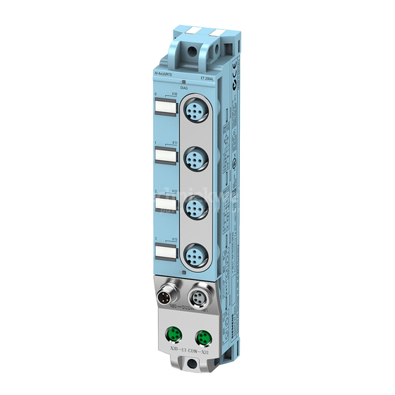
Page 9: Product Overview
Product overview Properties Article number 6ES7145-5ND00-0BA0 View of the module Figure 2-1 View of the analog output module AQ 4xU/I 4xM12 Analog output module AQ 4xU/I 4xM12 (6ES7145-5ND00-0BA0) Manual, 07/2019, A5E38687953-AB... - Page 10 ● M8 sealing cap ● M12 sealing cap See also You can find more information on accessories in the Accessories/spare parts section of the ET 200AL distributed I/O system (https://support.industry.siemens.com/cs/us/en/view/89254965) system manual. Analog output module AQ 4xU/I 4xM12 (6ES7145-5ND00-0BA0) Manual, 07/2019, A5E38687953-AB...
-
Page 11: Operator Controls And Display Elements
Product overview 2.2 Operator controls and display elements Operator controls and display elements The figure below shows the operator controls and display elements of the AQ 4xU/I 4xM12 analog output module. ① DIAG: LED display for the diagnostic status ② X10 to X13: Sockets for the output signal ③... -
Page 12: Wiring
Wiring Terminal and block diagram The example in the following figure shows the pin assignment for voltage and current output of the analog output module AQ 4xU/I 4xM12. ① Voltage/current output as 2-wire connection Loop-through of the ET-Connection ② Voltage/current output as 4-wire connection Supply voltage 1L+ (non-switched) ③... -
Page 13: Pin Assignment
Wiring 3.2 Pin assignment Pin assignment Note Color coding The sockets for ET-Connection and the power supply of the modules are color-coded. These colors correspond to the colors of the offered cables. Pin assignment of the sockets for analog outputs The tables below show the pin assignments of the 4 sockets for connection of the analog outputs. - Page 14 Wiring 3.2 Pin assignment Table 3- 2 Pin assignment of the sockets for analog outputs (current output) Assignment Front view of the sockets X10 to X13 - sockets for analog outputs (current output) 24 V actuator supply 1U (derived from 1L+ Non-Switched) Current output positive QI +: Connector X10 Current output positive QI...
- Page 15 Wiring 3.2 Pin assignment Pin assignment of the connector for infeed of the supply voltage The table below shows the pin assignment of the connector for infeed of the supply voltage. Table 3- 4 Pin assignment of the supply voltage connector Assignment Assignment of the Front view of the...
-
Page 16: Parameters/Address Space
Parameters/address space Output ranges The table below indicates which output types and ranges are configurable. Output type and output ranges Table 4- 1 Output type and output ranges Output type Output range Disabled Voltage +/- 10 V 0 V to 10 V 1 V to 5 V Current +/- 20 mA... -
Page 17: Parameters
Parameters/address space 4.2 Parameters Parameters Parameters of the AQ 4xU/I 4xM12 analog output module The table below lists the parameters that can be set. The effective range of the parameters that can be set depends on the type of configuration. The following configurations are possible: ●... - Page 18 Parameters/address space 4.2 Parameters Parameters Value range Default GSD file GSD file PROFINET IO PROFIBUS DP Reaction to CPU/master Shut down Channel Module Shut down • STOP Keep last value • Output substitute • value Substitute value See section Explana- Channel Channel tion of the parameters...
-
Page 19: Explanation Of The Parameters
Parameters/address space 4.3 Explanation of the parameters Explanation of the parameters Output type/range channel n With this parameter, you set the output type or output range for the channel to control the actuator. Note Unused channels "Deactivate" unused channels in the parameter assignment to improve the power consumption of the module. - Page 20 Parameters/address space 4.3 Explanation of the parameters Substitute value With this parameter, you set substitute values for the analog outputs. The table below shows the permitted value ranges for the substitute values: Table 4- 3 Permissible substitute values for the output ranges Output type Output range Valid substitute value...
-
Page 21: Address Space
Parameters/address space 4.4 Address space Address space The following figure shows the assignment of the address space for the AQ 4xU/I 4xM12 analog output module with value status (Quality Information (QI)). The address space for the value status is occupied by the module if the value status is configured using the PROFINET interface module. -
Page 22: Interrupts/Diagnostics Alarms
Interrupts/diagnostics alarms Status and error displays LED displays The figure below shows the LED display (status and error displays) of the AQ 4xU/I 4xM12 analog output module. ① Diagnostic status (DIAG) (red/green) ② Channel status (0, 1, 2 and 3) (green) Figure 5-1 LED displays Analog output module AQ 4xU/I 4xM12 (6ES7145-5ND00-0BA0) - Page 23 Interrupts/diagnostics alarms 5.1 Status and error displays Meaning of the LEDs The following tables set out the meaning of the status and error displays. Corrective measures for diagnostics alarms can be found in the section Diagnostics alarms (Page 23). DIAG LED Table 5- 1 Error display of the DIAG LED DIAG LED...
-
Page 24: Interrupts
Interrupts/diagnostics alarms 5.2 Interrupts Interrupts The AQ 4xU/I 4xM12 analog output module supports diagnostics interrupts. Diagnostic interrupt The module generates a diagnostic interrupt at the following events: ● Short-circuit of the actuator supply ● Short-circuit (voltage) ● Wire break (current) ●... -
Page 25: Technical Specifications
Technical specifications of the AQ 4xU/I 4xM12 analog output module The following table shows the technical specifications as of 05/2019. You will find a data sheet including daily updated technical specifications on the Internet (https://support.industry.siemens.com/cs/ww/en/pv/6ES7145-5ND00-0BA0/td?dl=en). Article number 6ES7145-5ND00-0BA0 General information... - Page 26 Technical specifications Article number 6ES7145-5ND00-0BA0 Output current Total current 1 A up to 45 °C; 0.5 A up to 55 °C Rated value • Power loss Power loss, typ. 2.6 W Analog outputs Number of analog outputs Voltage output, short-circuit protection Voltage output, short-circuit current, max.
- Page 27 Technical specifications Article number 6ES7145-5ND00-0BA0 Errors/accuracies Output ripple (relative to output range, band- 0.02 % width 0 to 50 kHz), (+/-) Linearity error (relative to output range), (+/-) 0.1 % Temperature error (relative to output range), 0.005 %/K (+/-) Crosstalk between the outputs, max. -70 dB Repeat accuracy in steady state at 25 °C (rela- 0.03 %...
- Page 28 Technical specifications Article number 6ES7145-5ND00-0BA0 Ambient conditions Ambient temperature during operation -30 °C min. • 55 °C max. • Connection method Design of electrical connection for the inputs M12, 5-pole and outputs Design of electrical connection for supply volt- M8, 4-pole ET-Connection M8, 4-pin, shielded ET-Connection...
-
Page 29: Profienergy
Additional information You can find additional information on working with PROFIenergy in the "PROFIenergy" section of the manual IM 157-1 PN interface module (https://support.industry.siemens.com/cs/ww/en/view/89254863) and the "Saving energy with PROFIenergy" section of function manual PROFINET with STEP 7 V14 (https://support.industry.siemens.com/cs/ww/en/view/49948856). -
Page 30: Response Of Analog Output Module
PROFIenergy 7.2 Response of analog output module Response of analog output module Display The channel status LEDs are not affected by PROFIenergy. Response to error detection All channels that are in pause mode on "PE_MODE_PROCEED" report their diagnostic status as in productive mode. The following conditions apply to all channels which switch to the pause mode "PE_MODE_SHUTDOWN": ●... - Page 31 PROFIenergy 7.2 Response of analog output module Mode parameter The following table shows the "Mode" parameter. Table 7- 1 Mode parameter Element Code Explanation Mode : PE_MODE_PROCEED Proceed at "pause" Value status "GOOD" • : PE_MODE_SHUTDOWN Switch off at "pause" Actuator supply U switched off •...
-
Page 32: Dimension Drawing
Dimension drawing The figure below shows the dimension drawing of the AQ 4xU/I 4xM12 analog output module in front and side view. Figure A-1 Dimension drawing Analog output module AQ 4xU/I 4xM12 (6ES7145-5ND00-0BA0) Manual, 07/2019, A5E38687953-AB... -
Page 33: Representation Of Analog Values
Representation of analog values This appendix shows the analog values for all output ranges supported by the AQ 4xU/I 4xM12 analog output module. Measured value resolution The digitized analog value is the same for all output values at the same nominal range. Analog values are output as fixed point numbers in two's complement. -
Page 34: Representation Of Analog Values In The Voltage Output Ranges
Representation of analog values B.1 Representation of analog values in the voltage output ranges Representation of analog values in the voltage output ranges The tables below list the decimal and hexadecimal values (codes) of the possible voltage output ranges. Table B- 2 Voltage output range +/-10 V Values Voltage output range Range... - Page 35 Representation of analog values B.1 Representation of analog values in the voltage output ranges Table B- 4 Voltage output range 1 to 5 V Values Voltage output range Range Dec. Hex. 1 V to 5 V 118.519% 32767 7FFF 5.70 V Maximum output value 32512 7F00...
-
Page 36: Representation Of Analog Values In The Current Output Ranges
Representation of analog values B.2 Representation of analog values in the current output ranges Representation of analog values in the current output ranges The tables below list the decimal and hexadecimal values (codes) of the possible current output ranges. Table B- 5 Current output range +/-20 mA Values Current output range... - Page 37 Representation of analog values B.2 Representation of analog values in the current output ranges Table B- 7 Current output range 4 mA to 20 mA Values Current output range Range Dec. Hex. 4 mA to 20 mA 118.5149% 32767 7FFF 21 mA Maximum output value 29377...
Need help?
Do you have a question about the SIMATIC ET 200AL and is the answer not in the manual?
Questions and answers