Christie Mirage SST Installation And Setup Manual
Hide thumbs
Also See for Mirage SST:
- Installation and setup manual (73 pages) ,
- Technical reference (66 pages) ,
- User manual (61 pages)
Table of Contents
Advertisement
Quick Links
Advertisement
Table of Contents

Related Manuals for Christie Mirage SST


Summary of Contents for Christie Mirage SST
- Page 1 Installation and Setup Guide 020-102956-08 Mirage SST...
- Page 2 Christie's control such as maintenance of the product in proper working conditions. Performance specifications are based on information available at the time of printing. Christie makes no warranty of any kind with regard to this material, including, but not limited to, implied warranties of fitness for a particular purpose.
-
Page 3: Table Of Contents
Display panel components..........24 Workflow: Installing and setting up the Mirage SST system......24 Setting up the projector head. - Page 4 Running Auto Setup to optimize display settings......56 Configuring Mirage SST to work with Christie Link......57 Disposing of the product packaging.
- Page 5 Dual-input 3D and HFR 2D..........74 Mirage SST Installation and Setup Guide 020-102956-08 Rev. 1 (09-2022) Copyright © 2022 Christie Digital Systems USA, Inc. All rights reserved. If printed, please recycle this document after use.
-
Page 6: Introduction
This projector is intended for use in a fixed install environment (also known as a cinema environment). This projector must be operated in an environment that meets the operating range specification. Use only the attachments and/or accessories recommended by Christie. Use of others may result in the risk of fire, shock, or personal injury. -
Page 7: Installation Safety And Warning Guidelines
Caution! If not avoided, the following could result in minor or moderate injury. • ELECTRICAL and BURN HAZARD! Use caution when accessing internal components. • Only Christie qualified technicians are authorized to use the tools provided in the toolbox. Mirage SST Installation and Setup Guide 020-102956-08 Rev. 1 (09-2022) Copyright ©... -
Page 8: Ac Power Precautions
• SHOCK HAZARD! A dedicated, protected ground or earth wire must be installed on the product by Christie qualified technicians or electricians before it can be connected to power. • SHOCK HAZARD! Disconnect the product from AC before installing, moving, servicing, cleaning, removing components, or opening any enclosure. -
Page 9: Light Intensity Hazard Distance
E—Represents the top view of the projector. • F—Represents the side view of the projector. Mirage SST Installation and Setup Guide 020-102956-08 Rev. 1 (09-2022) Copyright © 2022 Christie Digital Systems USA, Inc. All rights reserved. If printed, please recycle this document after use. - Page 10 Introduction The following table lists the hazard distance for the Christie projector lens with the zoom adjusted to its most hazardous position. For US and international hazard distances based upon IEC 62471-5:2015, Photobiological Safety of Lamps and Lamp Systems – Part 5: Image Projectors.
- Page 11 Hazard distance graph for Type A high brightness and ultra high contrast lenses: Mirage SST Installation and Setup Guide 020-102956-08 Rev. 1 (09-2022) Copyright © 2022 Christie Digital Systems USA, Inc. All rights reserved. If printed, please recycle this document after use.
- Page 12 • Temporary show installations containing Risk Group 3 laser-illuminated projectors may be installed by Christie or sold or leased only to valid laser light show variance holders (laser light show manufacturers) for image projection applications. Such manufacturers may currently hold a valid variance for production of Class IIIb and IV laser light shows and/or for incorporation of the Risk Group 3 laser-illuminated projectors into their shows.
-
Page 13: Third-Party Products
Learn about the labels that may be used on the product. Labels on your product may be yellow or black and white. General hazards Hazard warnings also apply to accessories once they are installed in a Christie product that is connected to power. Fire and Shock Hazard To prevent fire or shock hazards, do not expose this product to rain or moisture. -
Page 14: Mandatory Action
SHOCK HAZARD! Disconnect all power sources before performing maintenance or service procedures. Consult the service manual. Mirage SST Installation and Setup Guide 020-102956-08 Rev. 1 (09-2022) Copyright © 2022 Christie Digital Systems USA, Inc. All rights reserved. If printed, please recycle this document after use. -
Page 15: Electrical Labels
Laser Product - Risk Group 3 according to IEC 60825-1: 2014 and IEC 62471-5:2015 Indicates the product is certified for use with the listed Christie- supplied light illumination sources. Indicates a danger Class 4 laser radiation when open and interlocks are defeated. -
Page 16: Product Documentation
Introduction Product documentation For installation, setup, and user information, see the product documentation available on the Christie website. Read all instructions before using or servicing this product. 1. Access the documentation from the Christie website: • Go to this URL: http://bit.ly/2TI2aEW or https://www.christiedigital.com/en-us/3d/products-and-solutions/projectors/mirage-sst. -
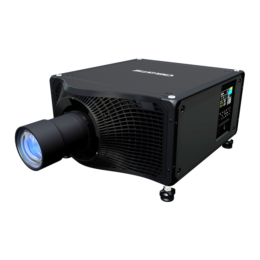
Page 17: Projector Overview
4K images up to 120 frames (for Mirage SST) per second. The systems can be 3P (single) or 6P (dual). Mirage SST provide several design and installation advantages. Their small form factor allows them to be installed independently, or as part of a multi-projector array, into tight, challenging environments. -
Page 18: How The Projector Works
LCD display to provide information at-a-glance How the projector works The Mirage SST accepts a variety of input signals for projection on front or rear projection screens, typical in commercial or other large screen applications. High-brightness light is generated by a laser illumination source, then fed to the projector through a fiber optic cable, where it is modulated by three Digital Micromirror Device (DMD) panels responding to incoming data streams of digitized red, green and blue color information. -
Page 19: Installation And Setup
Ensure a qualified electrician connects the AC power to the laser illumination source and chiller as per electrical codes. Mirage SST Installation and Setup Guide 020-102956-08 Rev. 1 (09-2022) Copyright © 2022 Christie Digital Systems USA, Inc. All rights reserved. If printed, please recycle this document after use. -
Page 20: Projector Components
Access to fold mirror, optical zoom/focus, and DMD convergence adjustments. Display panel Displays the projector menu and status. Mirage SST Installation and Setup Guide 020-102956-08 Rev. 1 (09-2022) Copyright © 2022 Christie Digital Systems USA, Inc. All rights reserved. If printed, please recycle this document after use. - Page 21 Indicates shutter status. Air filter side Provides access to the side air filter. Mirage SST Installation and Setup Guide 020-102956-08 Rev. 1 (09-2022) Copyright © 2022 Christie Digital Systems USA, Inc. All rights reserved. If printed, please recycle this document after use.
-
Page 22: Ir/Wired Remote Keypad
Powers on the projector light source. Opens the aspect ratio dialog. Mirage SST Installation and Setup Guide 020-102956-08 Rev. 1 (09-2022) Copyright © 2022 Christie Digital Systems USA, Inc. All rights reserved. If printed, please recycle this document after use. - Page 23 Male 3-pin XLR connector for wired option. Lock/unlock the keypad. Battery door. Mirage SST Installation and Setup Guide 020-102956-08 Rev. 1 (09-2022) Copyright © 2022 Christie Digital Systems USA, Inc. All rights reserved. If printed, please recycle this document after use.
-
Page 24: Display Panel Components
Workflow: Installing and setting up the Mirage SST system Identify the recommended order for installing and setting up the components of the Mirage SST system. These tasks detail the steps for installing both single (3P) and dual (6P) systems. For the dual system, repeat the tasks for both the left-eye and right-eye systems, making sure you connect the correct light source to the correct projector head. - Page 25 AC input cables Laser Ethernet cable The Mirage SST projector head provides all configuration and control for the laser illumination source. Never connect a laptop to the laser illumination source unless directed by Technical Support. 1. Set up the projector head (on page 26).
-
Page 26: Setting Up The Projector Head
1. To adjust the vertical position of the projector, extend or retract the adjustable feet on the bottom of the projector using the adjustable knobs on the feet. Christie recommends adjusting the feet from the side or rear of the projector and not the front to avoid exposure to the output light. -
Page 27: Installing The Projector Lens
2. Once the required adjustment is made, using a wrench, tighten the lock nut against the bottom of the projector. Installing the projector lens Only use lenses designed for Mirage SST projectors. Installing a lens not designed for Mirage SST, results in a warning that the lens is not present. 1. Turn off the lasers. -
Page 28: Connecting The Projector Head To Ac Power
1. Position the laser illumination source on level ground and make sure the fiber optic cable is routed in a way to avoid any damage. Mirage SST Installation and Setup Guide 020-102956-08 Rev. 1 (09-2022) Copyright © 2022 Christie Digital Systems USA, Inc. All rights reserved. If printed, please recycle this document after use. -
Page 29: Installing The J33 Terminal Block On The Laser Illumination Source
Power key in the remote position. For racks purchased before this date, contact Christie Technical Support for information on upgrading the laser rack to use this feature. Determine which terminal block and features you require: •... -
Page 30: Protecting The Fiber Connector
The fiber connector safety cover provides additional physical protection for the fiber connector to reduce the risk of damage during installation work. Mirage SST Installation and Setup Guide 020-102956-08 Rev. 1 (09-2022) Copyright © 2022 Christie Digital Systems USA, Inc. All rights reserved. If printed, please recycle this document after use. - Page 31 1. Slide a cable tie through the eye of the wire lanyard and loop the cable tie loosely around the fiber optic cable. Mirage SST Installation and Setup Guide 020-102956-08 Rev. 1 (09-2022) Copyright © 2022 Christie Digital Systems USA, Inc. All rights reserved. If printed, please recycle this document after use.
- Page 32 7. Slide the tethered safety cover back to the connector end and place the cover over the fiber connector and its dust cap. Mirage SST Installation and Setup Guide 020-102956-08 Rev. 1 (09-2022) Copyright © 2022 Christie Digital Systems USA, Inc. All rights reserved. If printed, please recycle this document after use.
-
Page 33: Connecting The Fiber Optic Cable To The Projector Through The Curved Strain Relief
4. To remove the top clamp from the bottom of the strain relief, remove the four screws. Mirage SST Installation and Setup Guide 020-102956-08 Rev. 1 (09-2022) Copyright © 2022 Christie Digital Systems USA, Inc. All rights reserved. If printed, please recycle this document after use. - Page 34 9. Gently slide the fiber optic cable into the fiber input ensuring the red dots line up. Mirage SST Installation and Setup Guide 020-102956-08 Rev. 1 (09-2022) Copyright © 2022 Christie Digital Systems USA, Inc. All rights reserved. If printed, please recycle this document after use.
-
Page 35: Connecting The Fiber Optic Cable To The Projector Through The Straight Strain Relief
1. Remove the curved portion of the strain relief. Mirage SST Installation and Setup Guide 020-102956-08 Rev. 1 (09-2022) Copyright © 2022 Christie Digital Systems USA, Inc. All rights reserved. If printed, please recycle this document after use. - Page 36 Re-install the clamp to the pieces to the straight portion of the strain relief using the two screws removed in step b. Mirage SST Installation and Setup Guide 020-102956-08 Rev. 1 (09-2022) Copyright © 2022 Christie Digital Systems USA, Inc. All rights reserved. If printed, please recycle this document after use.
- Page 37 10. Gently slide the fiber optic cable into the fiber input ensuring the red dots line up. Mirage SST Installation and Setup Guide 020-102956-08 Rev. 1 (09-2022) Copyright © 2022 Christie Digital Systems USA, Inc. All rights reserved. If printed, please recycle this document after use.
-
Page 38: Connecting The Ethernet Cable To The Projector
1. Connect one end of an Ethernet cable to the Laser Rack network port on the IMXB of the projector. Mirage SST Installation and Setup Guide 020-102956-08 Rev. 1 (09-2022) Copyright © 2022 Christie Digital Systems USA, Inc. All rights reserved. If printed, please recycle this document after use. -
Page 39: Setting Up The Chiller Unit
1. Position the chiller on level ground. 2. Confirm the chiller can operate and maintain proper specifications as stated in the Mirage SST Projector Head Specifications Guide (P/N: 020-102994-04 or newer) as it is plumbed to the laser illumination source. -
Page 40: Performing Initial System Start-Up
Performing initial system start-up Learn how to turn on all components of the Mirage SST system for the first time: chiller, laser illumination source, and projector head. Warning! If not avoided, the following could result in death or serious injury. - Page 41 10. Turn on the lasers: Mirage SST Installation and Setup Guide 020-102956-08 Rev. 1 (09-2022) Copyright © 2022 Christie Digital Systems USA, Inc. All rights reserved. If printed, please recycle this document after use.
-
Page 42: Turning On The System
If a leak exists, after the leak is repaired, add premixed coolant at the recommended 2:1 ratio. Mirage SST Installation and Setup Guide 020-102956-08 Rev. 1 (09-2022) Copyright © 2022 Christie Digital Systems USA, Inc. All rights reserved. If printed, please recycle this document after use. - Page 43 The projector boots into standby mode after approximately 30 seconds. Mirage SST Installation and Setup Guide 020-102956-08 Rev. 1 (09-2022) Copyright © 2022 Christie Digital Systems USA, Inc. All rights reserved. If printed, please recycle this document after use.
- Page 44 (use test pattern if no source image is connected). Mirage SST Installation and Setup Guide 020-102956-08 Rev. 1 (09-2022) Copyright © 2022 Christie Digital Systems USA, Inc. All rights reserved. If printed, please recycle this document after use.
-
Page 45: Turning Off The System
Turning off the system Learn how to turn off all components of the Mirage SST system: projector head, laser, and chiller. When powering off in preparation for inspection or maintenance, always disconnect from AC. 1. To turn the light source off using the projector keypad or remote, press and hold the button until you hear a beep. -
Page 46: Projector Led Status Indicators
A problem exists with the projector that does not prevent it from operating. Mirage SST Installation and Setup Guide 020-102956-08 Rev. 1 (09-2022) Copyright © 2022 Christie Digital Systems USA, Inc. All rights reserved. If printed, please recycle this document after use. -
Page 47: Projector Led Shutter Indicators
1. Turn off the lasers. 2. Push in and hold the lens release button. Mirage SST Installation and Setup Guide 020-102956-08 Rev. 1 (09-2022) Copyright © 2022 Christie Digital Systems USA, Inc. All rights reserved. If printed, please recycle this document after use. -
Page 48: Aligning The Image
6. With a framing pattern on screen, double-check projector leveling so the top edge of the image is parallel to the top edge of the screen. Mirage SST Installation and Setup Guide 020-102956-08 Rev. 1 (09-2022) Copyright © 2022 Christie Digital Systems USA, Inc. All rights reserved. If printed, please recycle this document after use. -
Page 49: Selecting A Test Pattern
1. Close the shutter on the projector. 2. Unlock the three lens mount stabilization screws. Mirage SST Installation and Setup Guide 020-102956-08 Rev. 1 (09-2022) Copyright © 2022 Christie Digital Systems USA, Inc. All rights reserved. If printed, please recycle this document after use. - Page 50 Adjust the screw 1/4 turn. If you get to the end, further unlock the corresponding stabilization screw. Mirage SST Installation and Setup Guide 020-102956-08 Rev. 1 (09-2022) Copyright © 2022 Christie Digital Systems USA, Inc. All rights reserved. If printed, please recycle this document after use.
-
Page 51: Adjusting The Fold Mirror
4. Unlock the fold mirror screws to unlock the adjustment knobs. Mirage SST Installation and Setup Guide 020-102956-08 Rev. 1 (09-2022) Copyright © 2022 Christie Digital Systems USA, Inc. All rights reserved. If printed, please recycle this document after use. - Page 52 6. To make vertical adjustments, use the purple knob labeled Vertical. Mirage SST Installation and Setup Guide 020-102956-08 Rev. 1 (09-2022) Copyright © 2022 Christie Digital Systems USA, Inc. All rights reserved. If printed, please recycle this document after use.
-
Page 53: Optimizing The Integrator Zoom And Focus
2. Loosen the four screws securing the optics-side cover and remove it. Mirage SST Installation and Setup Guide 020-102956-08 Rev. 1 (09-2022) Copyright © 2022 Christie Digital Systems USA, Inc. All rights reserved. If printed, please recycle this document after use. - Page 54 Always focus the center of the image first and then make sure no blurry edges exist. Mirage SST Installation and Setup Guide 020-102956-08 Rev. 1 (09-2022) Copyright © 2022 Christie Digital Systems USA, Inc. All rights reserved. If printed, please recycle this document after use.
-
Page 55: Adjusting Dmd Convergence
3. To adjust the convergence knobs, use the 3 mm tool included with the projector. Mirage SST Installation and Setup Guide 020-102956-08 Rev. 1 (09-2022) Copyright © 2022 Christie Digital Systems USA, Inc. All rights reserved. If printed, please recycle this document after use. -
Page 56: Aligning The Image With Lens Zoom And Focus
4. Use the Convergence test pattern to assist with adjusting the horizontal and vertical lines. Vertical convergence and rotation is done by adjusting two knobs. Christie recommends rotating a single knob a maximum of a quarter rotation before adjusting the second knob a quarter rotation. -
Page 57: Configuring Mirage Sst To Work With Christie Link
On the Input selection page, select the appropriate input marked Christie Link. More than one input source may be listed as Christie Link, depending on how many signals are being sent from Christie Link. For example, 0-1, 0-2, and so on, where 0 is the slot number. -
Page 58: Connecting Devices And Establishing Communication
The IMXB has a variety of ports that can be used for control, 3D sync, upgrading, retrieving interrogators, and connecting audio. Mirage SST Installation and Setup Guide 020-102956-08 Rev. 1 (09-2022) Copyright © 2022 Christie Digital Systems USA, Inc. All rights reserved. If printed, please recycle this document after use. -
Page 59: Connecting A Video Source Using 3G Input Card
Physically connects a remote control to the projector. 3D Sync In/3D Sync Out Supported for 3D-enabled projectors. Ethernet Connects to the web user interface and can send Christie serial commands. RS232 Sends Christie serial commands using a standard RS232 serial cable. -
Page 60: Connecting A Video Source Using Displayport
HDMI, and 12G, 6G, 3G, and HD SDI sources. Part number: 144-116109-XX Connecting a video source using TSIC The Terra SDVoE (TSIC) input card accepts digital video data from a Christie Terra Transmitter. Part number: 144-132107-XX Mirage SST Installation and Setup Guide 020-102956-08 Rev. -
Page 61: Selecting A Video Source
Connecting to a computer or server Communicate with a remote computer, server, or an existing network using a RJ-45 cable. The RS232 port located on the IMXB faceplate uses the Christie proprietary protocol and is intended for Christie accessories or automation controllers only. -
Page 62: Configuring The Rs232 Port
Configuring the RS232 port Configure the RS232 port to send Christie serial commands using a standard RS232 serial cable. For more information, on the serial commands, see the Mirage SST Serial Commands Guide (P/N: 020-103005-XX) . 1. Select Menu > Communications > Projector Communication. -
Page 63: 3D Setup
(dual-input 3D) Mirage SST Installation and Setup Guide 020-102956-08 Rev. 1 (09-2022) Copyright © 2022 Christie Digital Systems USA, Inc. All rights reserved. If printed, please recycle this document after use. -
Page 64: 3D System Timing
2. Select the appropriate 3D mode: • Off—Disable the 3D operation. Mirage SST Installation and Setup Guide 020-102956-08 Rev. 1 (09-2022) Copyright © 2022 Christie Digital Systems USA, Inc. All rights reserved. If printed, please recycle this document after use. -
Page 65: Confirming The Emitter Setup
Connect the 3D Sync Input to the video source for synchronization of the left eye/right eye frames of Direct input 3D or for frame doubled content. Mirage SST Installation and Setup Guide 020-102956-08 Rev. 1 (09-2022) Copyright © 2022 Christie Digital Systems USA, Inc. All rights reserved. If printed, please recycle this document after use. - Page 66 IR Emitter for active glasses or a polarization device for passive glasses. Mirage SST Installation and Setup Guide 020-102956-08 Rev. 1 (09-2022) Copyright © 2022 Christie Digital Systems USA, Inc. All rights reserved. If printed, please recycle this document after use.
-
Page 67: Regulatory
(01/2016) on the control of pollution caused by electronic information products, hazardous Mirage SST Installation and Setup Guide 020-102956-08 Rev. 1 (09-2022) Copyright © 2022 Christie Digital Systems USA, Inc. All rights reserved. If printed, please recycle this document after use. - Page 68 Regulation (EC) No. 1907/2006 on the registration, evaluation, authorization and restriction of chemicals (REACH) and the applicable official amendment(s). Mirage SST Installation and Setup Guide 020-102956-08 Rev. 1 (09-2022) Copyright © 2022 Christie Digital Systems USA, Inc. All rights reserved. If printed, please recycle this document after use.
-
Page 69: Signal Connectivity Specifications For
The list of formats listed below are not exhaustive and other formats may be supported. For more information, contact Christie Technical Support. For a list of supported Christie Link video formats, see the Christie Link User Manual (P/N: 020-102234-XX). HBMIC video formats Identify the video formats for the HBMIC card. - Page 70 RGB/4:4:4 10/12bpc — 4096x2160 4096 2160 50, 60 4:2:2 10bpc — Mirage SST Installation and Setup Guide 020-102956-08 Rev. 1 (09-2022) Copyright © 2022 Christie Digital Systems USA, Inc. All rights reserved. If printed, please recycle this document after use.
-
Page 71: Tsic Video Formats
8/10bpc 3840x2160 1920 2160 RGB/4:4:4 8/10bpc 4096x2160 2048 2160 RGB/4:4:4 8/10bpc Mirage SST Installation and Setup Guide 020-102956-08 Rev. 1 (09-2022) Copyright © 2022 Christie Digital Systems USA, Inc. All rights reserved. If printed, please recycle this document after use. -
Page 72: Tdpic Video Formats
Bit-depth Notes HD 1280x720 — 1280 RGB/4:4:4 8bpc Dual-link (120 Hz) Mirage SST Installation and Setup Guide 020-102956-08 Rev. 1 (09-2022) Copyright © 2022 Christie Digital Systems USA, Inc. All rights reserved. If printed, please recycle this document after use. -
Page 73: Thic Video Formats
1280x720 — 1280 24, 25, 30, 50, 60 4:2:2 10bpc — Mirage SST Installation and Setup Guide 020-102956-08 Rev. 1 (09-2022) Copyright © 2022 Christie Digital Systems USA, Inc. All rights reserved. If printed, please recycle this document after use. -
Page 74: Dual-Input 3D And Hfr 2D
Frame rate (Hz) Sampling Bit-depth 1280x720 1280 24, 25, 30, 60 4:2:2 10bpc Mirage SST Installation and Setup Guide 020-102956-08 Rev. 1 (09-2022) Copyright © 2022 Christie Digital Systems USA, Inc. All rights reserved. If printed, please recycle this document after use. - Page 75 24, 25, 30 RGB/4:4:4 8/10bpc Cannot use both TDPIC inputs at Mirage SST Installation and Setup Guide 020-102956-08 Rev. 1 (09-2022) Copyright © 2022 Christie Digital Systems USA, Inc. All rights reserved. If printed, please recycle this document after use.
- Page 76 RGB/4:4:4/4:2:2 8/10/12bpc 2048x1080 2048 1080 24, 25, 30, 60 RGB/4:4:4/4:2:2 8/10/12bpc Mirage SST Installation and Setup Guide 020-102956-08 Rev. 1 (09-2022) Copyright © 2022 Christie Digital Systems USA, Inc. All rights reserved. If printed, please recycle this document after use.
- Page 77 RGB/4:4:4 10/12bpc Level-A recommended 4096x2160 2048 1080 4:2:2 10bpc Level-A recommended Mirage SST Installation and Setup Guide 020-102956-08 Rev. 1 (09-2022) Copyright © 2022 Christie Digital Systems USA, Inc. All rights reserved. If printed, please recycle this document after use.
Need help?
Do you have a question about the Mirage SST and is the answer not in the manual?
Questions and answers